In the past I wrote about HomeBridge and Homekit2MQTT. In the past wrote several blogs about sensors, lamps, etc. for both home-bridges. The bridges where installed on a Raspberry Pi®. I made a little summary for those that are new to my site.
HomeBridge
HomeBridge – Relays & Lights
HomeBridge – Temperature & Humidity
HomeBridge – RGB Light
HomeBridge – NEOPixel Light
HomeBridge – Door Lock
HomeKit2MQTT
HomeBridge – MQTT controlling a Led
HomeBridge – MQTT Temperature & Humidity Sensor
HomeBridge – MQTT NeoPixel
HomeBridge – MQTT Button
HomeBridge – MQTT Blinds
HOMEBRIDGE
HomeBridge and Homekit2MQTT is a utility that some wonderful geniuses wrote to allow you to tie together all of the various “almost smart” home devices into Apples new HomeKit framework for Siri to control. If you want to learn more about Siri and HomeKit then I would suggest you start reading Apple’s website for some examples and details. Now that you are familiar with Siri and HomeKit we can move onto using HomeBridge. HomeBridge is a utility that needs to be run on a device that can stay powered on all the time in the background. Ideally you will want something that doesn’t consume lots of power or resources. That’s where the Raspberry Pi comes in.
These examples work all just fine…. But wouldn’t it be great if we don’t need a bridge at all!

ESP HomeKit SDK
In my previous blog I wrote about ESP HomeKit SDK.Here I investigated how to make the nessacarry bin fles. The ESP HomeKit SDK Creates a smarter and safer home devices for Apple HomeKit. The ESP HomeKit SDK has been designed such that it provides the HomeKit functionality independent of the transport (Wi-Fi/BLE/Ethernet). The sample accessory implementations provide a good starting point for developing HomeKit accessories with standard as well as custom features. The ESP HomeKit SDK is supported on ESP flagship chip ESP32 as wel on the ESP8266 chips. The high performance and low power consumption of the ESP chips target a variety of devices within Apple’s smart home platform. Apple’s HomeKit Protocol offers an end-to-end encryption and authentication between all HomeKit-enabled accessories and iOS devices. The Espressif HomeKit SDK ensures this desired security for the solution by means of hardware and software features of the Espressif platform. Apple HomeKit technology provides an easy, secure way to control your home’s lights, doors, thermostats, and more from your iPhone, iPad, or Apple Watch.

Use of the Works with Apple HomeKit logo means that an electronic accessory has been designed to connect specifically to iPod touch, iPhone, or iPad, respectively, and has been certified by the developer to meet Apple performance standards. Apple is not responsible for the operation of this device or its compliance with safety and regulatory standards.
Apple, Apple Watch, iPad, iPhone are trademarks of Apple Inc., registered in the U.S. and other countries. HomeKit is a trademark of Apple Inc.
Well there it is…. you don’t need a home bridge any more to add devices to your home kit.

ESP Microchip
To build our HomeKit device we only need a ESP826, ESP8285 or a ESP32. The ESP8266 is a low-cost Wi-Fi microchip with full TCP/IP stack and microcontroller capability produced by manufacturer Espressif Systems in Shanghai, China.
 |
 |
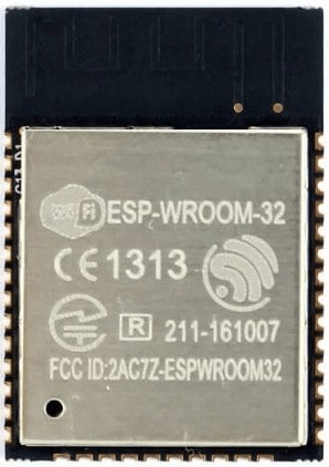 |
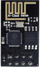
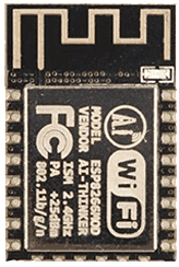
| ESP8266-12 | ESP8266-12F | ESP-32 |
The chip first came to the attention of western makers in August 2014 with the ESP-01 module, made by a third-party manufacturer Ai-Thinker. This small module allows microcontrollers to connect to a Wi-Fi network and make simple TCP/IP connections using Hayes-style commands. However, at first there was almost no English-language documentation on the chip and the commands it accepted. The very low price and the fact that there were very few external components on the module, which suggested that it could eventually be very inexpensive in volume, attracted many hackers to explore the module, chip, and the software on it, as well as to translate the Chinese documentation. The ESP8285 is an ESP8266 with 1 MiB of built-in flash, allowing for single-chip devices capable of connecting to Wi-Fi. The successor to these microcontroller chips is the ESP32.

Writing a program to the ESP8266
Flashing a program to the ESP8266 is a bit more annoying than flashing an Arduino. When flashing the arduino, all you have to do is press the reset button and release while you upload a program (or even not doing anything if you have FTDI such as in arduino UNO,NANO, MICRO, etc.) and the arduino will start uploading. With the ESP8266 you have to reset the micro-controller and start it in flashing mode using the GPIO0-to-Ground.
ESP8266-01 Scheme
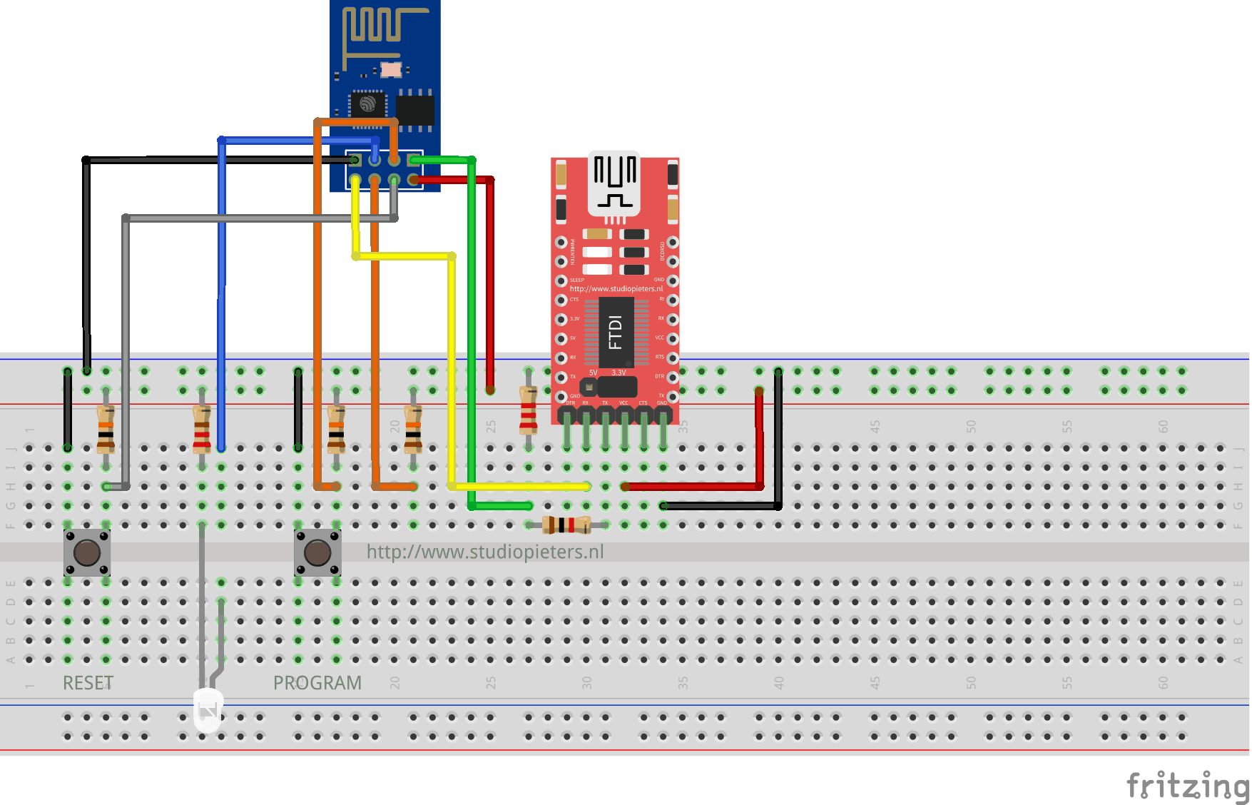
ESP8266-12F Scheme
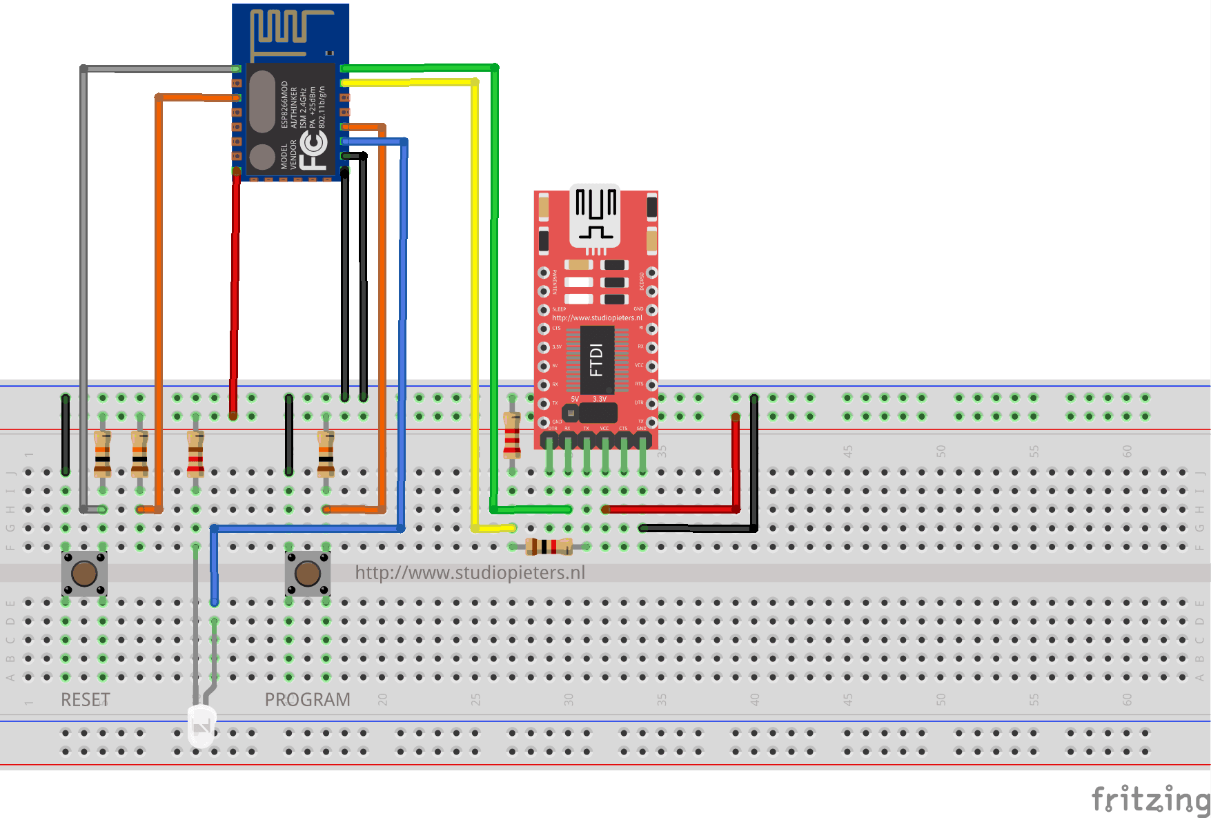
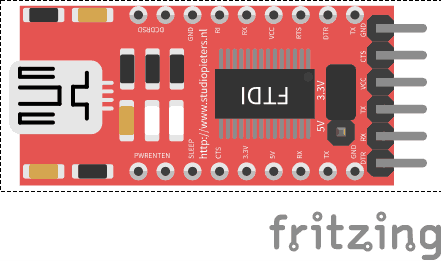
The sketch shows the ESP8266 connected to FTDI Programmer with a voltage regulator onboard.
NOTE: Be Sure that you have the Jumper placed on the 3.3V setting and not the 5V setting because this will destroy your ESP module!

As you can see two buttons have been added. The Left button, when pressed, connects the RESET pin to the ground and when it is released, connects the RESET pin to the VCC through a pull-up resistor.
The Right button, when pressed, connects the PROGRAM pin to the ground and when it is released, connects the PROGRAM pin to the VCC through a pull-up resistor.
I also added A LED when the ESP is in PROGRAMMING STATE state the LED is ON. When The ESP is in “NORMAL” state the LED is OFF. Using this two buttons you can do all the tasks you need with the ESP8266:
- Working on NORMAL mode – Both buttons are released.
- RESETTING the ESP8266 – Press the RESET button and release.
- Start in FLASH MODE – Press both buttons, release the RESET button and then release the PROGRAM button.
Install esptool.py
Esptool.py is a python script that retrieves information about your ESP8266 module and flashes its firmware.
Prepare the ESP8266
If you are a beginner, we will use the Terminal to perform all the steps of this blog. You can find it in applications, in the Utilities folder, or by entering Terminal in Spotlight. Provide an FTDI module if your module is equipped with a programming interface via aCOM port.
Esptool.py requires Python 2.7 which is normally the default on Mac OS X. To find out if python is already present on your machine, simply type the python command in the Terminal. If everything is properly installed you should have a message like this
Python 2.7.10 (default, Aug 22 2015, 20:33:39)
[GCC 4.2.1 Compatible Apple LLVM 7.0.0 (clang-700.0.59.1)] on darwin
Type "help", "copyright", "credits" or "license" for more information.
If this is not the case install the latest version of python by visiting there site here. Do not forget to leave python by entering exit (), quit () or Ctrl + D before continuing.
Make a directory (or the directory of your choice, it is equal) like this
cd ~/esptool
We will download the esptool by cloning it from github with command.
git clone https://github.com/themadinventor/esptool.git
Go to the esptool directory
cd esptool
Now we will execute the script setup.py which allows to add the necessary dependencies (in particular pySerial). You will need to enter your password to allow the command to run.
sudo python setup.py install
Installation with OTA update system Life-Cycle-Manager (LCM)
At first you need to download three bin files otaboot.bin, rboot.bin and blank_config.bin. The OTAboot.bin contains the Lifce-Cycle-Manager part. The rboot.bin contains the bootloader for the ESP8266. The blank_config.bin in just a blank config file. Now connect your device to your FTDI adapter in flash-mode.
Putting Device Into Flash Mode
To enable ESP8266 firmware flashing GPIO0 pin must be pulled low before the device is reset. Conversely, for a normal boot, GPIO0 must be pulled high or floating. Start in FLASH MODE – Press both buttons, release the RESET button and then release the PROGRAM button.
Use esptool.py to flash it in your device. First, erase flash:
esptool.py -p /dev/ erase_flash
Normally, your ESPPort will be something like /dev/tty.USB0000. Then, set your device in flash-mode again, and flash the new firmware:
esptool.py -p /dev/tty.USB0000 --baud 115200 write_flash -fs 1MB -fm dout -ff 40m \
0x0 rboot.bin 0x1000 blank_config.bin 0x2000 otaboot.bin
Note: If you use an old version of esptool, you must change -fs 1MB to -fs 8m.
You must configure wifi network and OTA repository. To configure wifi settings, device generates its own Wifi in AP mode. You must connect to it in order to setup your wifi network. Simply take your iOS device, go to Setting -> Wi-Fi, and search a SSID with LCM- followed of last MAC address, connect to it, and wait a few seconds until a web appears showing you all wifi networks that the device has found. Select yours, and enter password. Don’t touch Join button yet!!
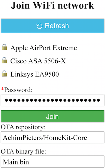
Now, you must configure OTA repository as well. It’s very important that you configure it right, because you can not change it in the future (If you make a mistake, you must erase and flash device again).
OTA repository:
AchimPieters/HomeKit-Core
OTA binary file:
main.bin
To finish initial setup, click Join button and wait about 7 minutes until process finish (While installation is working, device doesn’t show anything, and buttons don’t work). After that, LED turns on for a couple of seconds and you will be able to add your accessory to your HomeKit ecosystem using Home App. LCM will install your Homekt device on your ESP.

TIP: Open your Arduino IDE and then the serial monitor. now you can see the whole installation process!
HomeKit setup
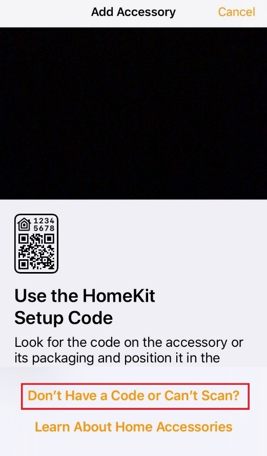
Now it’s time to add your HomeKit accessory.
Open the Home app on your iPhone. Tap Add Accessory. (If you already have other HomeKit accessories paired, tap + in the top-right corner to add an accessory.)
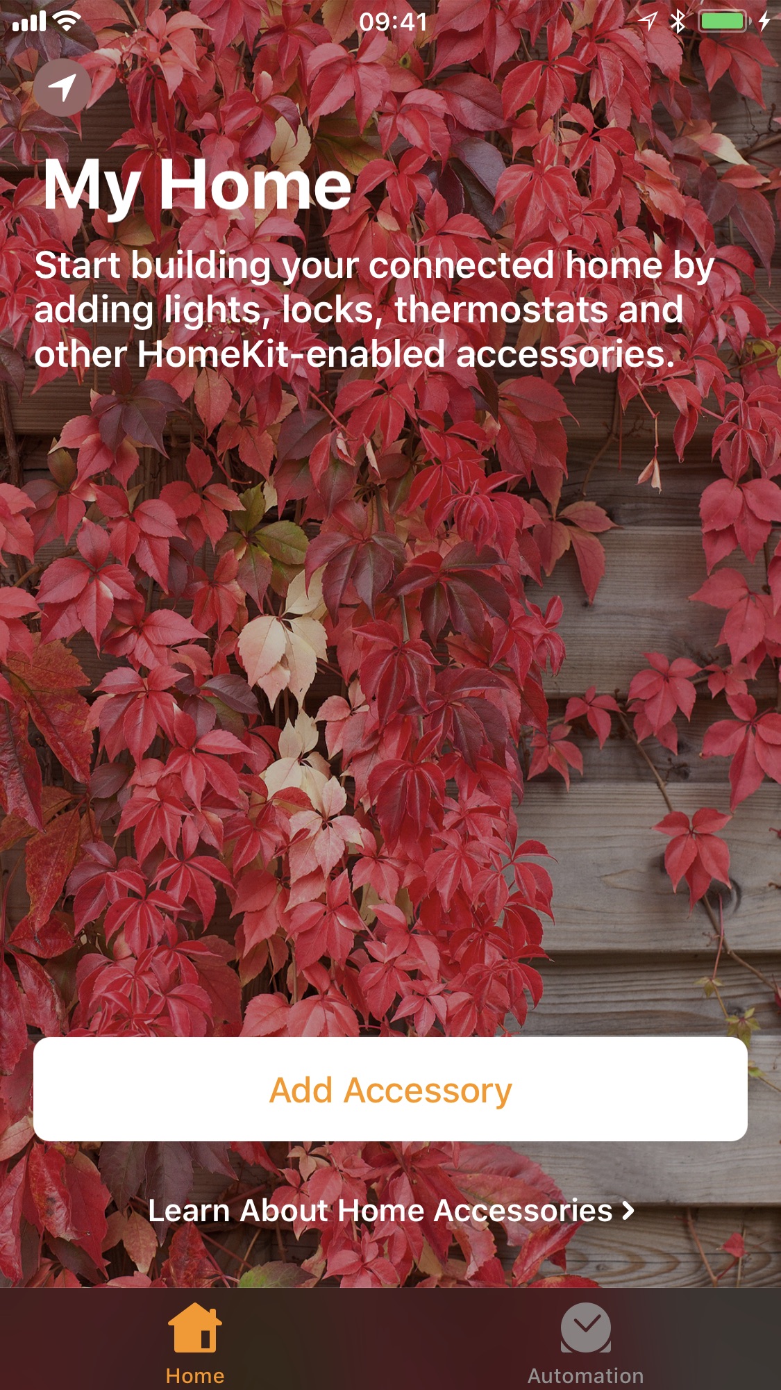
Select Don’t Have a Code or Can’t Scan?
You’ll see a list ( If you are to quick it will not show, just press enter code…) of all available devices currently on your network. Select StudioPieters LED-XXX from the list.
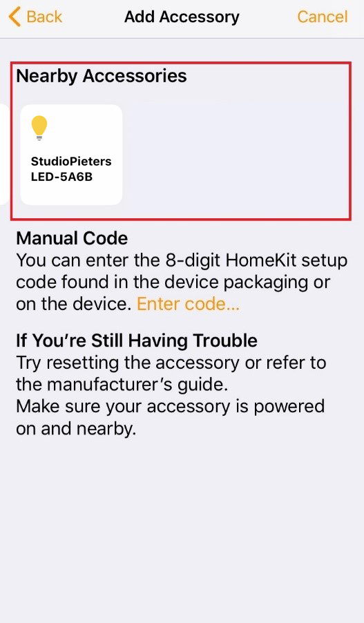
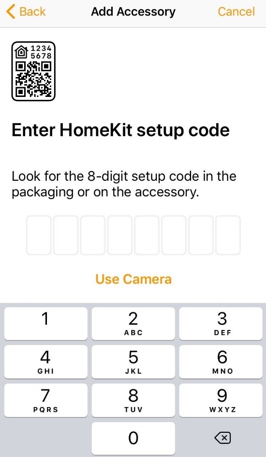
Enter the 8-digit homekit setup code:
111-11-111
The test
It takes about 30 seconds for HomeKit to make a connection. After setting up your device whe are ready to test ! Now simply press the reset button in your to turn on and off your LED light. Here in the little movie where I test my setup.
YES IT WORKS!
Next time I will make a HomeKit Switch and other accessories so come back soon!

DOWNLOAD ALL FILES FOR THIS PROJECT ON GITHUB.

DO YOU HAVE ANY QUESTIONS? LEAVE A COMMENT DOWN HERE.
Note: To produce and sell HomeKit compatible accessories, your company need to be certified for that (https://developer.apple.com/homekit/, If you’re interested in developing or manufacturing a HomeKit accessory that will be distributed or sold, your company must enroll in the MFi Program.) Espressif have their implementation of HomeKit framework, but it will give you it only if you have MFi certification (notice this text at the bottom of page you mentioned: Please note that the Espressif HomeKit SDK is available to MFi licensees only, and you need to provide the Account Number for verification purposes when requesting the SDK.).This project is a non-commercial implementation of HAP protocol, not meant for commercial use.
REFERENCE
Maxim Kulkin, esp-wifi-config (2019), Library to bootstrap WiFi-enabled accessories WiFi config, https://github.com/maximkulkin/esp-wifi-config Paul Sokolovsky, esp-open-sdk (2019), Free and open (as much as possible) integrated SDK for ESP8266/ESP8285 chips, https://github.com/pfalcon/esp-open-sdk Espressif Systems, esptool (2019), ESP8266 and ESP32 serial bootloader utility, https://github.com/espressif/esptool HomeACcessoryKid, life-cycle-manager (2019), Initial install, WiFi settings and over the air firmware upgrades for any esp-open-rtos repository on GitHub, https://github.com/HomeACcessoryKid/life-cycle-manager