For whom already visit my blog before know that after my website crashed, I could save a lot of posts, but unfortunately not all posts. This is one of them and I need to rewrite the whole blog. In this blog I will show you how to program a ESP8266-01 and a ESP8266-12F as I use these the most. First we need to instal some software so we can communicate with our ESP module.

Installing and Configuring
To get yourself a working environment go over these steps:
- Download the Arduino IDE.
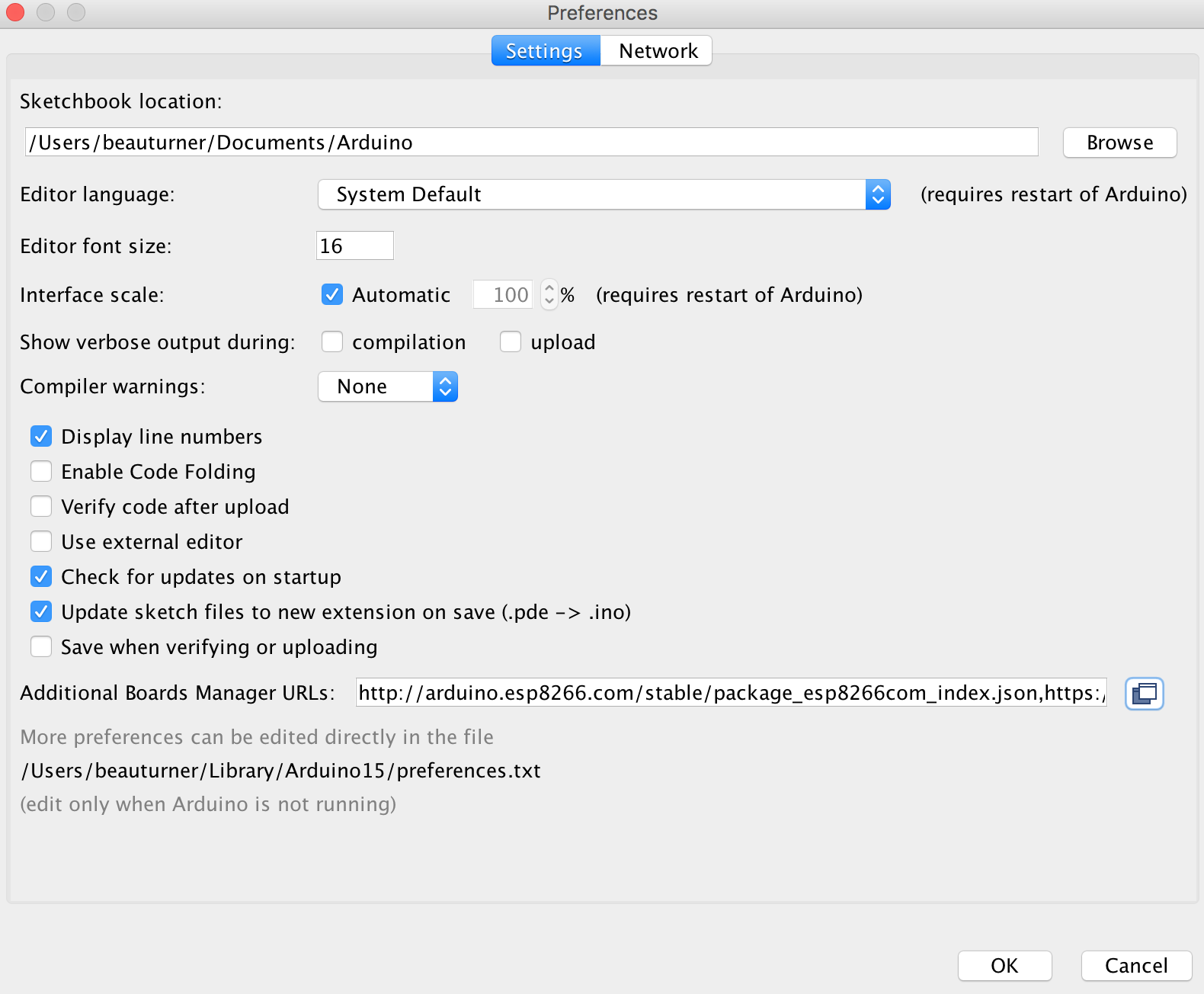
- Go to File –> Preferences and add the link http://arduino.esp8266.com/stable/package_esp8266com_index.json to the Additional Boards Manager URLS.
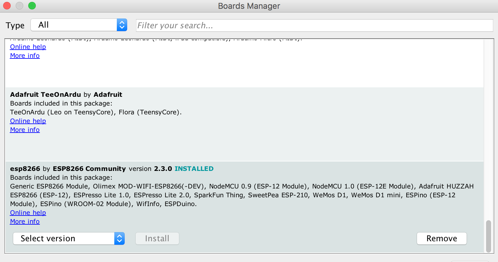
Go to Tools –> Board –> Boards manager
You should now have the esp8266 as an option there since you’ve added it to the Additional Boards. Select it and press Install.
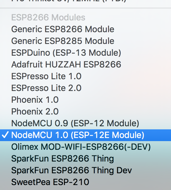
Now, You have the ESP8266 boards configure. Choose the board you have, “Generic ESP8266 Module” if you got the regular module and “NodeMCU 1.0 (ESP-12E Module)” if you have the ESP-12X module.
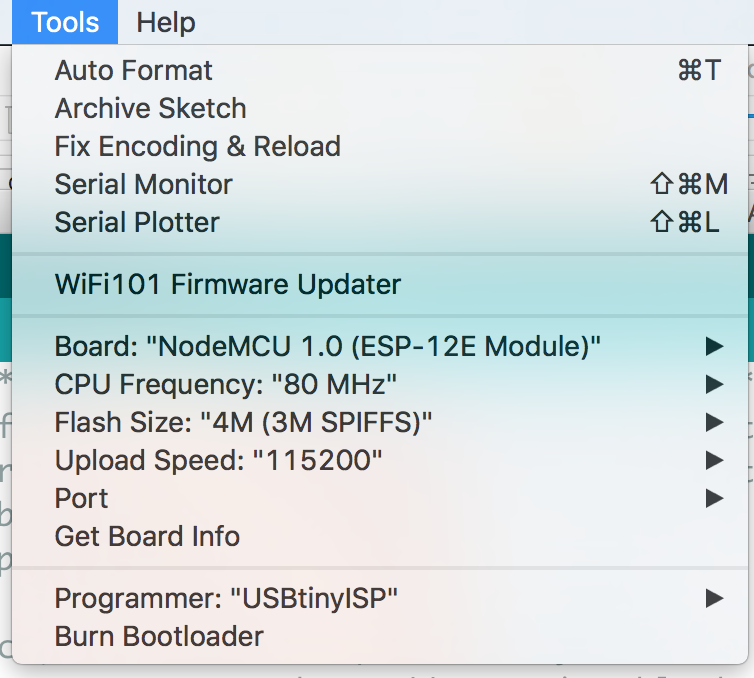
Choose the ESP8266 USB port when you connect your ESP module and you’re done!
And that’s it, you are ready. From what I understood by digging through the files, the new code interpreting the common arduino functions into a clear c++ code, then using the esptool to create a new firmware and flash it on the ESP8266.
Writing a program to the ESP8266
Flashing a program to the ESP8266 is a bit more annoying than flashing an Arduino. When flashing the arduino, all you have to do is press the reset button and release while you upload a program (or even not doing anything if you have FTDI such as in arduino UNO,NANO, MICRO, etc.) and the arduino will start uploading. With the ESP8266 you have to reset the micro-controller and start it in flashing mode using the GPIO0-to-Ground.
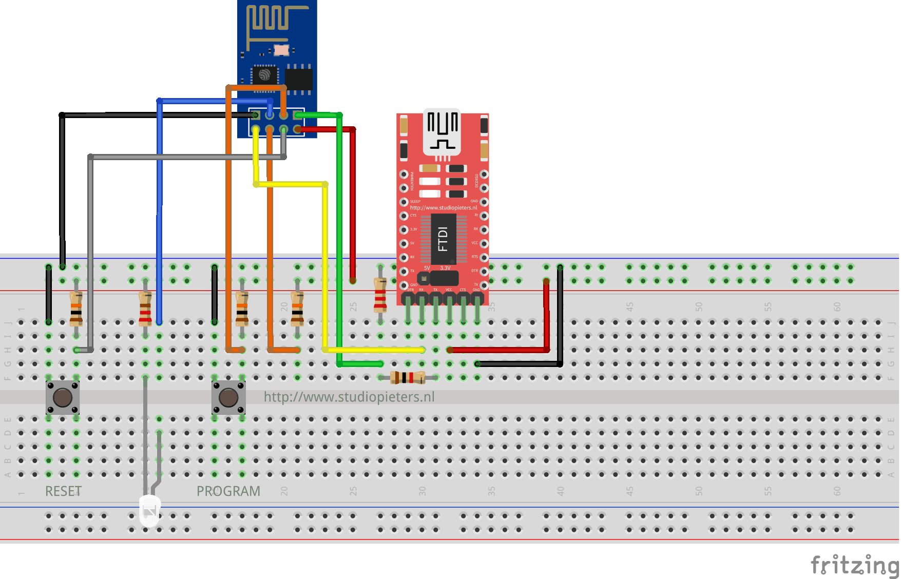
ESP8266-01 Scheme
ESP8266-12F Scheme
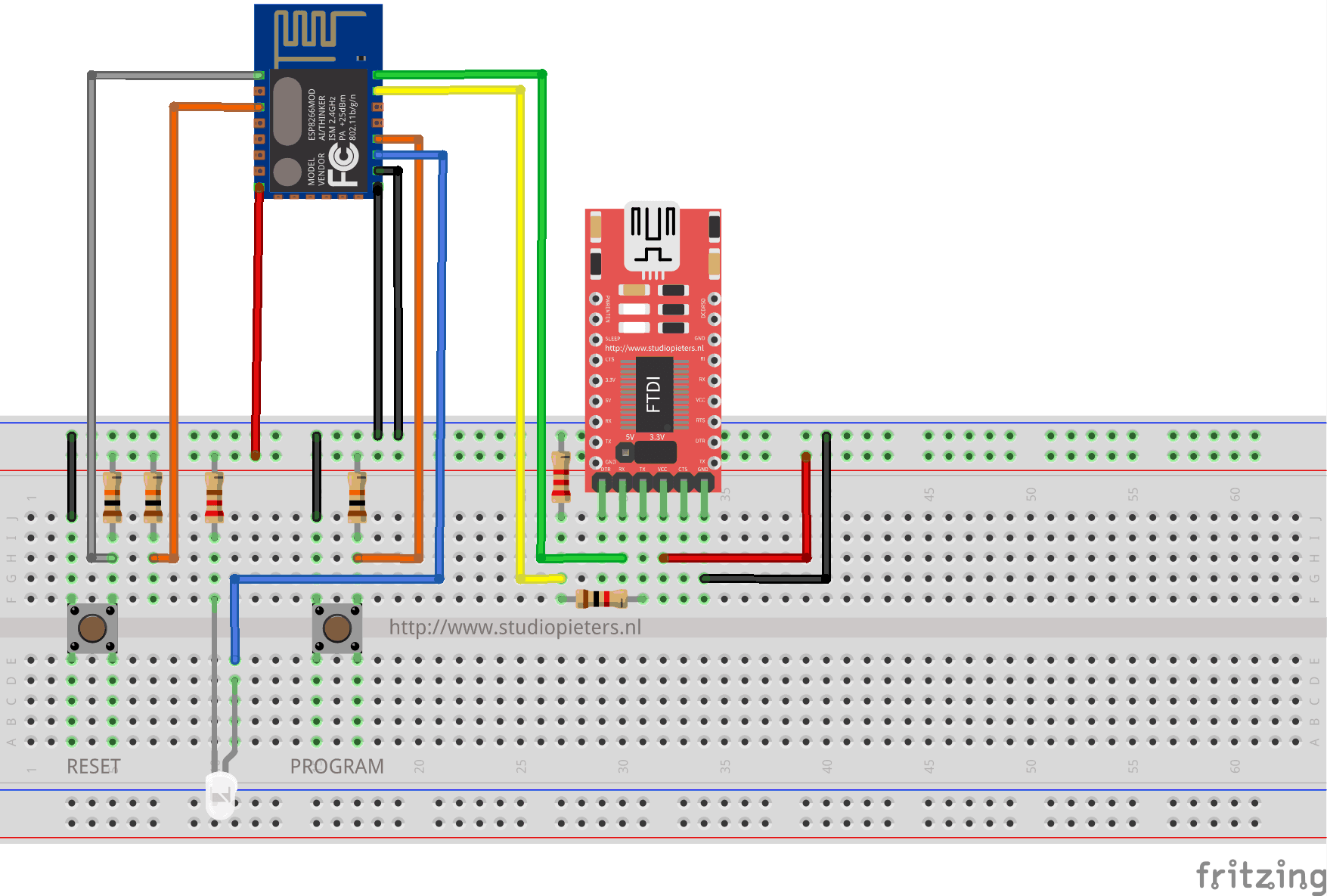
The sketch shows the ESP8266 connected to FTDI Programmer with a voltage regulator onboard.
NOTE: Be Sure that you have the Jumper placed on the 3.3V setting and not the 5V setting because this will destroy your ESP module!

As you can see two buttons have been added. The Left button, when pressed, connects the RESET pin to the ground and when it is released, connects the RESET pin to the VCC through a pull-up resistor.
The Right button, when pressed, connects the PROGRAM pin to the ground and when it is released, connects the PROGRAM pin to the VCC through a pull-up resistor.
I also added A LED when the ESP is in PROGRAMMING STATE state the LED is ON. When The ESP is in “NORMAL” state the LED is OFF. Using this two buttons you can do all the tasks you need with the ESP8266:
- Working on NORMAL mode – Both buttons are released.
- RESETTING the ESP8266 – Press the RESET button and release.
- Start in FLASH MODE – Press both buttons, release the RESET button and then release the PROGRAM button.
Programming your ESP module
Now your ready to program your ESP module. You can connect the USB cable from the FTDI programmer to your computer and open Arduino IDE. Happy programming.
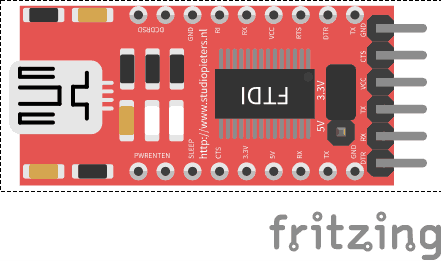
FRITZING PART
Because I always use the Fritzing app to illustrate the hardware setup of a new project, I need a new fritzing part for future setup’s. So after some designing in illustrator this is the end result.
DOWNLOAD ALL FILES FOR THIS PROJECT ON GITHUB.
