Remember the movie “Edge of Tomorrow“? (also known by its marketing tagline Live. Die. Repeat.) Cage is killed in combat, he finds himself in a time loop that sends him back to the day preceding the battle every time he dies. Kinda like the ESP8266 when it repeatedly resetting… Nothing you try makes a difference! Time for some Troubleshooting!

If you have worked with the ESP8266 for any length of time, you have undoubtedly experienced the endless resets on power-up. The looping message occurs at about 5 second intervals, which seems to be the default internal watchdog timer time-out period. The message, at 115200 baud, looks something like this:
ets Jan 8 2013,rst cause:4, boot mode:(3,7)
wdt reset
load 0x4010f000, len 1264, room 16
tail 0
chksum 0x0f
csum 0x0f
~ld
Troubleshooting
I have yet to come across a definitive explanation for this behavior. Is this the boot-loader? The core firmware? Perhaps a chip defect? From what I have experienced and read from other users, there are two likely hardware causes that makes logical sense:
Inadequate power supply interface
A flash chip failure.
In order to prevent resets, you must include the following three features in the power source to the ESP8266.
Sufficient current. A regulated 3.3V source of at least 500mA is essential. Aside from the 300mA peak current needs of the ESP8266, it is essential to also consider the current requirements for other components you have – like the sensors and controls in your circuit.
A large capacitor (suggest using 470 μF) across the Vcc to Gnd rails on your breadboard or PCB is a vital ingredient that will minimize reset inducing voltage fluctuations.
A 0.1 μF decoupling capacitor across the ESP8266 Vcc to Gnd inputs very close to the pins (within 1/2 inch). DO NOT SKIP THIS COMPONENT! This cheap yet often overlooked component, when missing, is the root cause of ESP8266 resets.
Even with these power supply precautions, we know the flash chip (25Q40) used with many of these ESP8266 module is of low quality and fails after only a few flash cycles. Perhaps sending the code somewhere that it never returns from. Triggering the watchdog timer to reset the unit.
If the power supply measures noted above are in place, but you are still experiencing resets, here are a few steps I have been taking with some success to bring back to life an ESP8266 stuck in a ‘Live. Die. Repeat.’ reset loop:
DEBUGGING
With the basic troubleshooting done it’s time for some debugging.

Check your connections
This seems obvious. But I have not seen this to be a problem with other MPUs, like an Arduino, Spark Core and even PIC processors.
But my first two ESP8266 set-ups use a standard solder-less breadboard. I have heard that the ESP8266 is very sensitive to intermittent connections, and the solder-less breadboard is not recommended. And sure enough, it has been a problem in my setup. While I have since switched to use soldered contacts on a prototyping PCB-board, I am still using the two original breadboards for initial testing. Using these units to limit the flash cycles on the more permanent soldered set-ups.
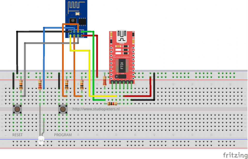
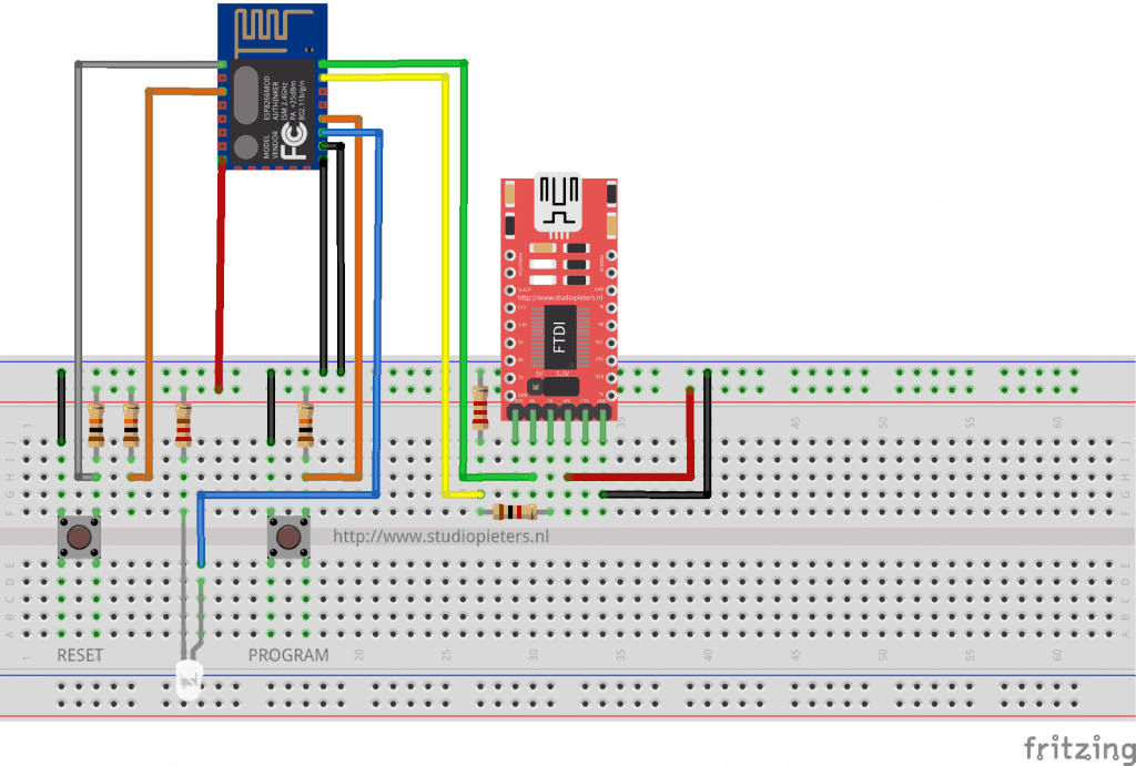
After many frustrating and unsuccessful attempts to revive my original setup out of reset purgatory, I made a final inspection of the jumpers and found a few of them only partially engaged. After securing all the connections again… The phoenix rose from the ashes. Yes, I had just about given up on this unit And now, the next flash successfully restored the set-up with out it’s reset loops.

Clear the memory
Along with securing connections, flashing some of the original binaries back into the module has always worked for me to clear the reset problem, so far. As I have already mentioned, it appears that the code gets stuck somewhere that it never returns from, resulting in a wdt reset. This would seem to be as result of corrupted memory. So clearing the flash memory, if possible, should correct the endless reset condition. Here is what I have found to work:
Flash AT command set
Flash the ESP8266 with original AT command binary. In case you do not have the flasher, one place to get it: on the manufactures website here. Restarting the module in normal mode (GPIO2 HI) should result in a 115200 baud start-up message ending with “Ready”. And it should respond to the “AT” command with “OK”.
Flash blank.bin
Flashing the blank.bin file, which comes with the nodemcu flasher program, is another method to clear the memory. Using the nodemcu flasher, flash the 4K blank.bin to the following 5 starting addresses: 0x00000, 0x01000, 0x40000, 0x7c000, 0x7e000 Then repeat “Flash AT command set” above.
Background information
Identifying Reset Cause Using User Program.
rst cause
| Number | Description |
|---|---|
| 0 | unknown |
| 1 | normal boot |
| 2 | reset pin |
| 3 | software reset |
| 4 | watchdog reset |
boot mode
the first value respects the pin setup of the Pins 0, 2 and 15.
| Number | GPIO15 | GPIO0 | GPIO2 | Mode |
|---|---|---|---|---|
| 0 | 0V | 0V | 0V | Not valid |
| 1 | 0V | 0V | 3.3V | Uart |
| 2 | 0V | 3.3V | 0V | Not valid |
| 3 | 0V | 3.3V | 3.3V | Flash |
| 4 | 3.3V | 0V | 0V | SDIO |
| 5 | 3.3V | 0V | 3.3V | SDIO |
| 6 | 3.3V | 3.3V | 0V | SDIO |
| 7 | 3.3V | 3.3V | 3.3V | SDIO |
I hope this information will help you troubleshoot your ESP problems!