
Reference
ESP32-S3-CAM-OVxxxx Pinout (Waveshare)
The complete pin reference for the Waveshare ESP32-S3-CAM-OVxxxx: camera, microSD, audio, display, I2C and UART connectors, the I/O expander and how to program it.
- ESP32
- 18 min read
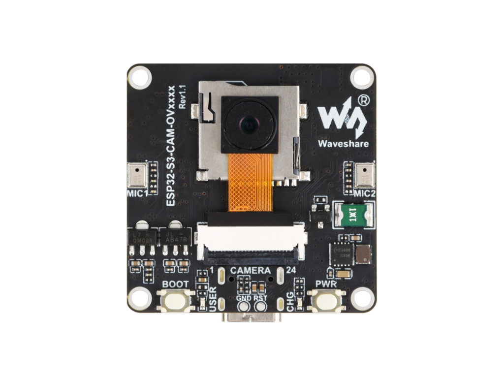
The ESP32-S3-CAM-OVxxxx is Waveshare’s compact AI camera board: an ESP32-S3 with 16 MB of flash and 8 MB of PSRAM, a 24-pin camera connector, a microSD slot, two microphones, an audio codec with speaker output, a battery charger and an 18-pin display connector, all on a square PCB of just 37 x 37 mm. The OVxxxx in the name stands for the camera sensor you choose: the board is sold with an OV5640, OV3660, GC2145 or GC0308 module.
It is a very different board from the cheap ESP32-S3-CAM boards with two rows of pin headers. This board has no pin headers at all. Everything leaves the board through connectors: an I²C connector, a UART connector, a display connector, a speaker connector and a battery connector. This guide covers every connector, chip and GPIO, and shows you which signals are on which pin.
The pin data in this guide comes from Waveshare’s own Rev 1.1 schematic and the Waveshare wiki. The silkscreen on the board reads ESP32-S3-CAM-OVxxxx Rev1.1. If yours says something else, compare it with the wiki first, because the V1.0 and V1.1 boards differ in a few details (see the gotchas).
System-on-chip and board
The ESP32-S3R8 is Espressif’s dual-core Xtensa LX7 chip (up to 240 MHz) with Wi-Fi 4 (802.11 b/g/n, 2.4 GHz only), Bluetooth 5 LE and a full-speed USB OTG interface. The “R8” means the chip has 8 MB of octal PSRAM stacked inside the package. Two features make it a good camera chip: a dedicated camera (DVP) interface that moves frames into memory without loading the CPU, and vector instructions that speed up image processing and small neural networks such as face and object detection.
| Item | Value |
|---|---|
| Chip | ESP32-S3R8, dual-core Xtensa LX7, up to 240 MHz |
| Memory | 512 KB SRAM, 384 KB ROM, 8 MB PSRAM (inside the chip), 16 MB external flash |
| Wireless | Wi-Fi 4 (2.4 GHz) and Bluetooth 5 LE. No Classic Bluetooth, no 5 GHz |
| Antenna | Ceramic antenna on the board. An IPEX 1 (u.FL) connector for an external antenna is also fitted: you must change a resistor to use it |
| USB | One USB-C port, wired to the chip’s native USB (GPIO19 and GPIO20) |
| Camera | 24-pin FPC connector, DVP interface. Sensor module included |
| Storage | microSD (TF) card slot |
| Audio | ES8311 codec, ES7210 microphone ADC, two onboard microphones, 3 W / 4 ohm speaker output |
| Display | 18-pin FPC for SPI and QSPI LCDs, with touch signals |
| Battery | 3.7 V lithium battery, MX1.25 2-pin connector, charging and discharging |
| Buttons | BOOT and PWR, plus GND and RST pads |
| Size | 37 x 37 mm, four mounting holes |
What is on the board
| Part | What it does |
|---|---|
| ESP32-S3R8 | Main processor with 8 MB PSRAM |
| 16 MB flash (XMC XM25QH128) | Program and file storage |
| ES8311 | Audio codec: plays sound to the speaker amplifier |
| ES7210 | Audio ADC: records the two microphones |
| NS4150B | 3 W class-D speaker amplifier |
| CH32V003F4U6 | A small RISC-V microcontroller used as I/O expander. It handles the power button, battery sense, LEDs and a few control lines |
| ETA6098 | Lithium battery charger |
| TMI3112H | Step-down converter that makes the 3.3 V rail from the battery or USB supply |
| RT9166A-28 and RT9166A-15 | Two LDO regulators for the camera sensor: 2.8 V for the analog and I/O supply, 1.5 V for the core |
| PTC fuse | Resettable fuse on the supply |
Board overview
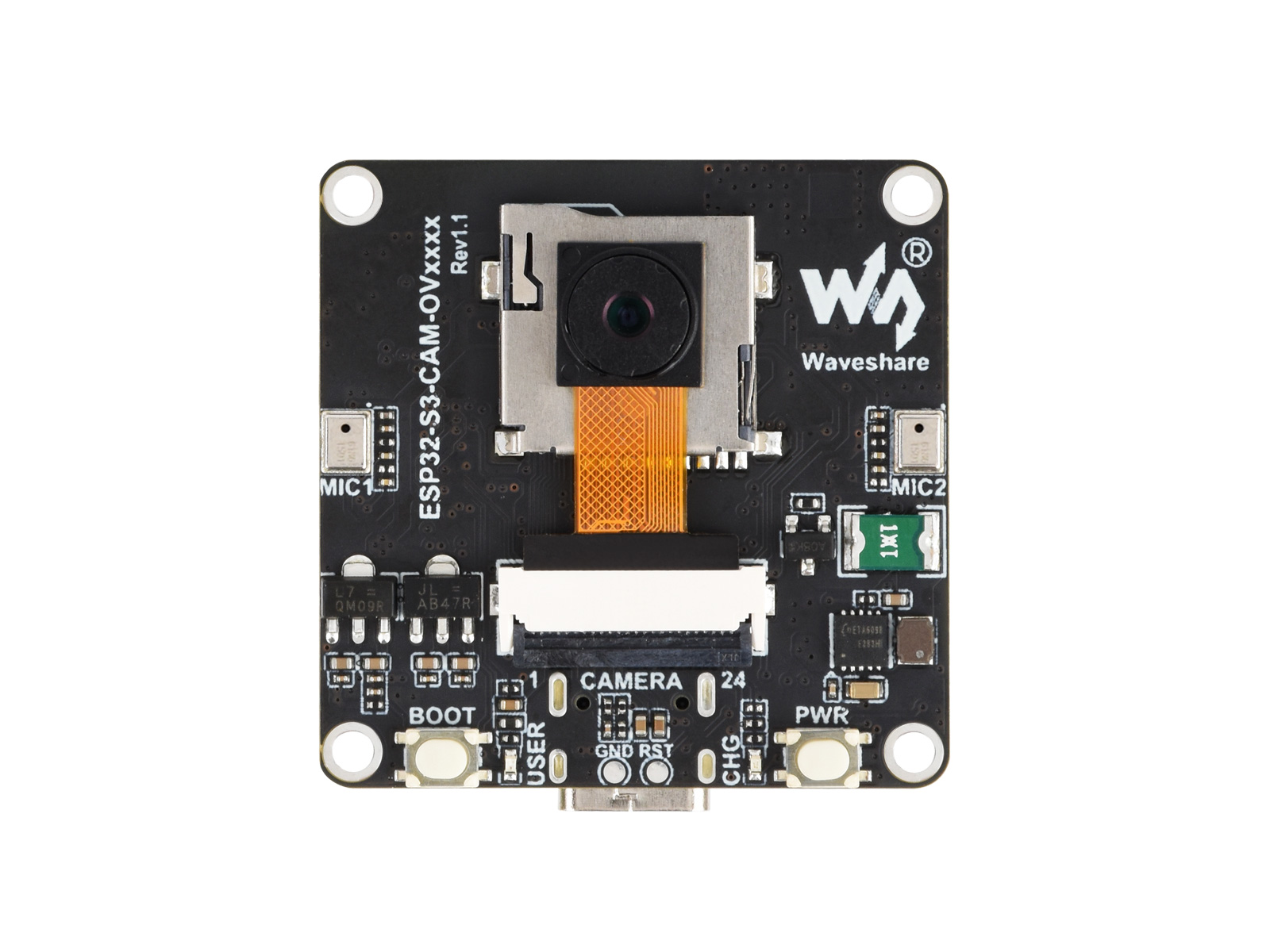
The camera side has the sensor on its flexible cable, the microSD slot underneath it, the two microphones (MIC1 and MIC2) and the BOOT and PWR buttons. The camera connector is right below the sensor.
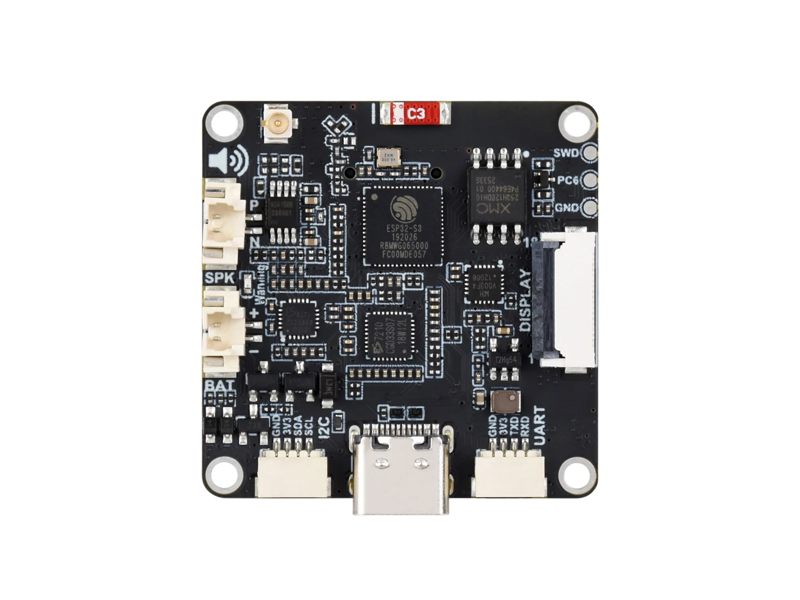
The back is where the electronics and all connectors are: the ESP32-S3, the codec chips, the speaker and battery connectors on the left, the I²C and UART connectors at the bottom next to the USB-C port and the display connector on the right.


No 802.15.4 radio on this chip, so Thread and Zigbee are not possible here: that needs an ESP32-C6 or H2 instead. No classic Bluetooth and no Wi-Fi 5, 6 or 7 either: this is 2.4 GHz 802.11 b/g/n and Bluetooth 5 LE. Only badges for what this exact chip supports are shown.
Getting started
The three steps below use the Arduino IDE and the USB-C port. If you prefer ESP-IDF, Waveshare publishes a board support package (see Programming further down).
The pin values in the programming section are derived from the schematic and not yet run on a board, so start with a small frame size.
Dimensions
The board is a square of 37 x 37 mm with rounded corners (radius 2.25 mm). The four mounting holes are 32.6 mm apart in both directions, with their centres 2.2 mm from each edge.

Pinout diagram: connector side
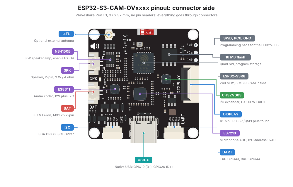
This side has all connectors. The ESP32-S3 sits in the middle, the audio chips below it, and the I/O expander next to the display connector.
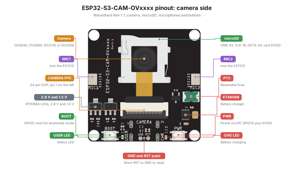
Pinout diagram: camera side
The camera side has the buttons, the LEDs and the two small pads you can use to reset the board.
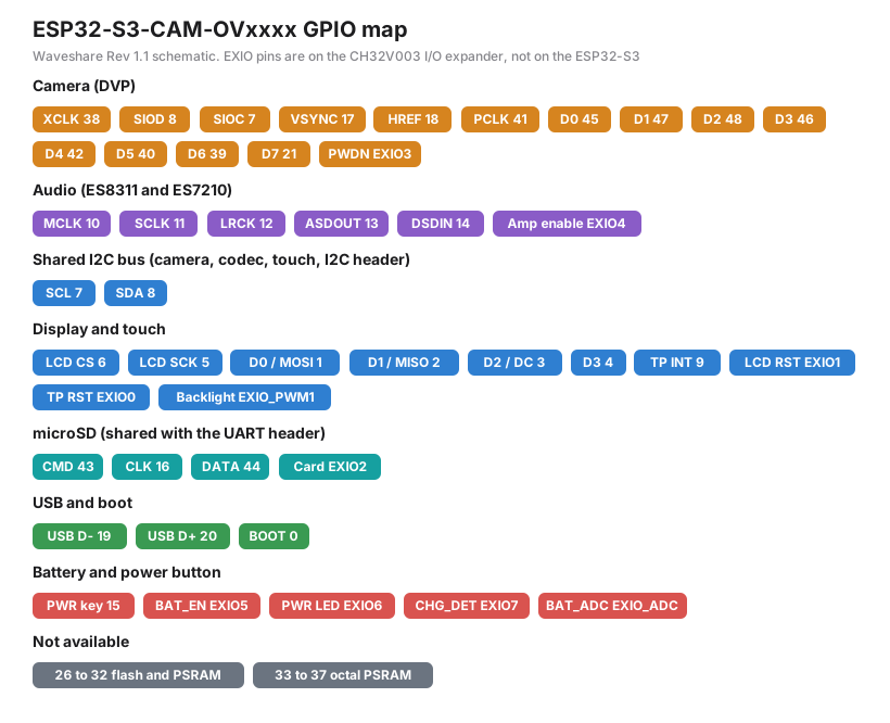
GPIO map at a glance
This is the most useful picture of the board. Almost every GPIO of the ESP32-S3 has a fixed job, so a plain “free GPIO” does not exist here. The pins marked EXIO are not ESP32-S3 pins: they are on the I/O expander chip.
The camera modules (OVxxxx)
All four modules use the same 24-pin connector and the same pins, so the board runs the same code. The driver detects the sensor automatically.
| Sensor | Max resolution | Output formats | Lens | Field of view (D / H / V) |
|---|---|---|---|---|
| OV5640 (5 MP) | 2592 x 1944 | RGB565, YUV, YCbCr422 | 1/4 inch, 4.1 mm, f/2.8 | 68 / 55 / 42 degrees |
| OV3660 (3 MP) | 2048 x 1536 | 8/10-bit raw RGB, JPEG, YUV, RGB565 | 3.2 mm, f/2.4 | 68 degrees (diagonal) |
| GC2145 (2 MP) | 1616 x 1232 | RGB565, YCbCr422, 8-bit raw RGB | 1/5 inch, 2.38 mm, f/2.4 | 68 / 60 / 46.8 degrees |
| GC0308 (VGA) | 648 x 488 | Grayscale, YCbCr422, RGB565 | 1/6.5 inch, 2.5 mm, f/2.4 | 58 / 46 / 35 degrees |
Which one? The OV5640 gives the sharpest picture and is the best choice for photos and detail. The GC0308 is only VGA but is light on memory and fast, enough for simple motion and presence detection. The OV3660 and GC2145 sit in between. The sensors listed here are the ones Waveshare sells for this board.
The flex cable is fragile. Open the black latch of the FPC connector, slide the cable in straight with the contacts facing the board, and close the latch again. Do not unplug it while the board is powered.
Camera connections (DVP interface)
The camera uses a parallel interface: a clock from the chip, a control bus, three sync signals and eight data lines. These GPIOs are wired to the camera connector.
| Camera signal | Pin | What it does |
|---|---|---|
| XCLK | GPIO38 | Master clock from the ESP32-S3 to the sensor |
| SIOD (SDA) | GPIO8 | Camera control bus data. Shared with the other I²C devices |
| SIOC (SCL) | GPIO7 | Camera control bus clock. Shared with the other I²C devices |
| VSYNC | GPIO17 | Start of a new frame |
| HREF | GPIO18 | Valid pixels in a line |
| PCLK | GPIO41 | Pixel clock from the sensor |
| D0 | GPIO45 | Data bit 0 |
| D1 | GPIO47 | Data bit 1 |
| D2 | GPIO48 | Data bit 2 |
| D3 | GPIO46 | Data bit 3 |
| D4 | GPIO42 | Data bit 4 |
| D5 | GPIO40 | Data bit 5 |
| D6 | GPIO39 | Data bit 6 |
| D7 | GPIO21 | Data bit 7 |
| PWDN | EXIO3 (I/O expander) | Power-down. A 10 k resistor pulls it low, so the camera is on by default |
| RESET | Not a GPIO | Has its own pull-up and capacitor, so it resets itself at power-up |
Note the unusual order of the data lines. They are not in a straight row, which is why you cannot use another board’s camera settings: the pins must be entered exactly as in this table.
The I/O expander (EXIO pins)
The ESP32-S3 has too few free pins for everything on this board, so Waveshare added a small CH32V003F4U6 microcontroller that works as an I/O expander. Its pins are named EXIO0 to EXIO7, plus an ADC input and a PWM output. These are not ESP32-S3 GPIOs: you cannot use digitalWrite(EXIO3, ...) directly. You reach them through the expander.
| Expander pin | Signal | Used for |
|---|---|---|
| EXIO0 | TP_RST | Touch panel reset (display connector) |
| EXIO1 | LCD_RST | Display reset (display connector) |
| EXIO2 | SD_CS / card pin | microSD card pin |
| EXIO3 | CAM_PWDN | Camera power-down |
| EXIO4 | PA_CTRL | Speaker amplifier enable |
| EXIO5 | BAT_EN | Battery power on and off (with the PWR button) |
| EXIO6 | PWR_LED | Power LED |
| EXIO7 | CHG_DET | Battery charge detection |
| EXIO_ADC | BAT_ADC | Battery voltage measurement |
| EXIO_PWM1 | LCD_BL | Display backlight (PWM) |
The easiest way to use the expander is Waveshare’s own driver code (their board support package for ESP-IDF and their Arduino examples). I do not describe the register protocol here, because I could not verify it from the schematic. The three small pads labelled SWD, PC6 and GND next to the display connector are for programming the expander chip itself. You normally never need them.
Audio: microphones, codec and speaker
The board has a full audio path. Two microphones (MIC1 and MIC2) are read by the ES7210 ADC. The ES8311 codec plays sound, through the NS4150B amplifier, to the speaker connector (3 W into 4 ohm, pins P and N). Both chips are set up over I²C and share one I²S audio bus.
| Signal | Pin | Description |
|---|---|---|
| I2S_MCLK | GPIO10 | Master clock to the codecs |
| I2S_SCLK | GPIO11 | Bit clock |
| I2S_LRCK | GPIO12 | Word select (left and right) |
| I2S_ASDOUT | GPIO13 | Audio data from the microphones to the ESP32-S3 |
| I2S_DSDIN | GPIO14 | Audio data from the ESP32-S3 to the speaker |
| I2C SCL / SDA | GPIO7 / GPIO8 | Codec configuration. The ES7210 has I²C address 0x40 |
| PA_CTRL | EXIO4 | Amplifier enable: switch it on before you play sound |
This makes the board suitable for voice assistants, wake-word detection and intercom projects with a camera. The speaker connector is a small MX1.25 2-pin plug; check the polarity (P and N are printed on the board).
microSD card
The microSD slot sits under the camera module on the front of the board. It is connected to the chip’s SD/MMC interface in 1-bit mode.
| SD signal | Pin | Notes |
|---|---|---|
| CMD | GPIO43 | Shared with UART0 TX |
| CLK | GPIO16 | |
| DATA (D0) | GPIO44 | Shared with UART0 RX |
| Card pin | EXIO2 | Through the I/O expander |
Format the card as FAT32. Because CMD and DATA are on GPIO43 and GPIO44, the UART connector and the SD card share pins. Use the SD card and the UART header not at the same time, and read the gotchas about the serial monitor.
Display connector
The 18-pin FPC connector next to the USB-C port drives an SPI or QSPI LCD, with touch panel signals as well. The same signals are given for the two modes.
| Signal | Pin | SPI name |
|---|---|---|
| LCD_CS | GPIO6 | |
| LCD_SCK | GPIO5 | |
| QSPI D0 / MOSI | GPIO1 | LCD_MOSI |
| QSPI D1 / MISO | GPIO2 | LCD_MISO |
| QSPI D2 / DC | GPIO3 | LCD_DC |
| QSPI D3 | GPIO4 | Not used in SPI mode |
| TP_SCL | GPIO7 | Touch I²C clock (shared bus) |
| TP_SDA | GPIO8 | Touch I²C data (shared bus) |
| TP_INT | GPIO9 | Touch interrupt |
| LCD_RST | EXIO1 | Display reset |
| TP_RST | EXIO0 | Touch reset |
| LCD_BL | EXIO_PWM1 | Backlight PWM |
Waveshare does not name the display on this page, so check the pin order of your own display against the connector. Remember that FPC cables for 18-pin displays can have the contacts on the same side or on opposite sides: buy a cable that matches. If you do not use a display, GPIO1 to GPIO6 and GPIO9 stay unused, but they can only be reached through this FPC connector.
I²C and UART connectors
Two small 4-pin connectors (SH1.0) give you your own communication ports. They have the same pin order: GND, 3V3 and then two signal pins.
| Connector | Pin 1 | Pin 2 | Pin 3 | Pin 4 |
|---|---|---|---|---|
| I2C | GND | 3V3 | SDA = GPIO8 | SCL = GPIO7 |
| UART | GND | 3V3 | TXD = GPIO43 | RXD = GPIO44 |
The I²C connector is the connector you will use most: it is how you add a sensor like a BME280 or a display, or the MCP23017 to get more pins. Keep in mind that this bus is shared with the camera control bus, the audio codecs and the display touch panel, so every device needs a different I²C address. The UART connector is 3.3 V logic and fits a GPS module or a serial sensor.
USB-C, flashing and reset
There is one USB-C port, and it is connected straight to the chip’s native USB (GPIO19 is D-, GPIO20 is D+). The board has no USB-to-UART bridge, so you flash it and see serial output through the native USB.
| Function | Pin | Description |
|---|---|---|
| BOOT | GPIO0 | Hold low at reset for download mode |
| USB D- / D+ | GPIO19 / GPIO20 | Native USB: flashing, serial (CDC), JTAG |
| RST pad | Chip EN | Short to the GND pad to reset the board |
| UART connector | GPIO43 / GPIO44 | Optional serial port, shared with the SD card |
If the upload does not start: hold BOOT, press and release a reset (touch the RST pad to the GND pad with a pair of tweezers), then let go of BOOT. Or hold BOOT while you plug in the USB cable.
Full GPIO reference
Every GPIO of the ESP32-S3 and what it does on this board.
| GPIO | Function | Notes |
|---|---|---|
| 0 | BOOT button | Low at reset starts download mode |
| 1 | Display QSPI D0 / MOSI | Display connector |
| 2 | Display QSPI D1 / MISO | Display connector |
| 3 | Display QSPI D2 / DC | Display connector |
| 4 | Display QSPI D3 | Display connector |
| 5 | Display SCK | Display connector |
| 6 | Display CS | Display connector |
| 7 | I²C SCL | Shared: camera control bus, codecs, touch, I2C connector |
| 8 | I²C SDA | Shared: camera control bus, codecs, touch, I2C connector |
| 9 | Touch interrupt | Display connector |
| 10 | I2S MCLK | Audio |
| 11 | I2S SCLK | Audio |
| 12 | I2S LRCK | Audio |
| 13 | I2S ASDOUT | Microphones to the ESP32-S3 |
| 14 | I2S DSDIN | ESP32-S3 to the speaker |
| 15 | PWR key | Power button |
| 16 | SD CLK | microSD |
| 17 | Camera VSYNC | Camera |
| 18 | Camera HREF | Camera |
| 19 | USB D- | Native USB |
| 20 | USB D+ | Native USB |
| 21 | Camera D7 | Camera |
| 26 to 32 | Flash and PSRAM link | Internal, not available |
| 33 to 37 | Octal PSRAM link | Internal, not available |
| 38 | Camera XCLK | Camera |
| 39 | Camera D6 | Camera |
| 40 | Camera D5 | Camera |
| 41 | Camera PCLK | Camera |
| 42 | Camera D4 | Camera |
| 43 | SD CMD and UART TX | Shared. UART connector TXD |
| 44 | SD DATA and UART RX | Shared. UART connector RXD |
| 45 | Camera D0 | Strapping pin (flash voltage) |
| 46 | Camera D3 | Strapping pin (boot mode and boot log) |
| 47 | Camera D1 | Camera |
| 48 | Camera D2 | Camera |
Programming
Arduino IDE, PlatformIO and ESP-IDF all work. Waveshare also publishes a board support package for ESP-IDF (the waveshare/esp32_s3_cam_ovxxxx component) and example code on its wiki. In the Arduino IDE choose ESP32S3 Dev Module and use these settings:
| Setting | Value |
|---|---|
| Flash size | 16MB (128Mb) |
| PSRAM | OPI PSRAM |
| Partition scheme | 16M Flash (for example 3MB APP / 9.9MB FATFS) |
| USB CDC On Boot | Enabled: otherwise Serial prints nothing |
| Upload mode | UART0 / Hardware CDC |
Enter the camera pins yourself. This is a working configuration for this board:
camera_config_t config = {};
config.ledc_channel = LEDC_CHANNEL_0;
config.ledc_timer   = LEDC_TIMER_0;
config.pin_d0 = 45;  config.pin_d1 = 47;
config.pin_d2 = 48;  config.pin_d3 = 46;
config.pin_d4 = 42;  config.pin_d5 = 40;
config.pin_d6 = 39;  config.pin_d7 = 21;
config.pin_xclk  = 38;
config.pin_pclk  = 41;
config.pin_vsync = 17;
config.pin_href  = 18;
config.pin_sccb_sda = 8;
config.pin_sccb_scl = 7;
config.pin_pwdn  = -1;   // on the I/O expander, pulled low
config.pin_reset = -1;
config.xclk_freq_hz = 20000000;
config.pixel_format = PIXFORMAT_JPEG;
config.frame_size   = FRAMESIZE_SVGA;
config.jpeg_quality = 12;
config.fb_count     = 2;
config.fb_location  = CAMERA_FB_IN_PSRAM;
config.grab_mode    = CAMERA_GRAB_LATEST;
I derived these values from Waveshare’s schematic and did not run them on a board myself, so start with a small frame size and check the result. If you also use the audio codecs in the same program, the camera and the codecs must share the I²C bus: set up the bus first and let the camera driver use it (pin_sccb_sda = -1 and sccb_i2c_port) instead of starting its own.
Getting the best picture
- Use JPEG in PSRAM. Let the sensor compress the frames (
PIXFORMAT_JPEG) and keep the buffers in PSRAM. Raw RGB565 frames are for image processing, not for streaming. - Pick the frame size on purpose. SVGA (800 x 600) is a good balance for a stream. Full OV5640 resolution is for still photos.
- Two buffers.
fb_count = 2withCAMERA_GRAB_LATESTavoids old frames in a live stream. - Flip and mirror. If the picture is upside down, use
s->set_vflip(s, 1)ands->set_hmirror(s, 1). - Heat. The board is small and gets warm while streaming. Leave some air around it and do not seal it into a box without ventilation.
- Light. Small sensors are poor in the dark. More light helps more than any setting.
Real gotchas
- No pin headers. You cannot plug this board into a breadboard. Use the I²C and UART connectors with SH1.0 cables, or a breakout for the display connector.
- There are almost no free GPIOs. Every ESP32-S3 pin has a job. With the display unused, GPIO1 to GPIO6 and GPIO9 are free but only reachable through the FPC connector. Add pins with an I²C expander on the I²C connector.
- The SD card and the UART connector share GPIO43 and GPIO44. Those are also the chip’s default serial pins. Enable USB CDC On Boot so the serial monitor uses the USB-C port, and do not connect a UART device and use the SD card together.
- EXIO pins are not GPIOs. Camera power-down, amplifier enable, the card pin, LEDs, battery control and the display reset are on the I/O expander. If the speaker is silent, the amplifier enable (EXIO4) is the first thing to check.
- The I²C bus is shared. Camera control, both audio codecs, the touch panel and the I²C connector all use GPIO7 and GPIO8. Do not add a second device with the same address.
- Strapping pins. The camera data lines D0 and D3 are on GPIO45 and GPIO46, which are read at power-up. Do not add pull-up or pull-down resistors to them.
- PSRAM must be enabled. Without OPI PSRAM in the build settings the camera driver fails with an out-of-memory error. This chip needs OPI, not QSPI.
- “Camera probe failed with error 0x105”. The chip cannot talk to the sensor. Check that the flex cable is fully inserted and the latch is closed, and that the pin numbers match the table above.
- Hardware versions differ. Rev 1.1 has a changed RF circuit, camera circuit changes, a battery reverse protection circuit and a lower charge current compared to V1.0. Read the wiki for your version.
- Brownouts. A weak USB port or thin cable causes resets when Wi-Fi and the camera start together.
- Battery safety. Check the polarity of the battery connector. Do not leave charging lithium batteries unattended.
- 3.3 V logic. The I²C and UART connectors are not 5 V tolerant.
- Privacy and security. A camera and microphones on your network are a risk. Do not expose the stream to the internet, set a password and keep the firmware up to date.
Compared with other camera boards
The numbers below are for the common versions of these boards.
| Waveshare ESP32-S3-CAM-OVxxxx | ESP32-CAM (AI-Thinker) | XIAO ESP32S3 Sense | |
|---|---|---|---|
| Chip | ESP32-S3R8, dual core | ESP32, dual core | ESP32-S3, dual core |
| Flash and PSRAM | 16 MB and 8 MB | 4 MB and 4 MB | 8 MB and 8 MB |
| Native USB | Yes, one USB-C | No | Yes |
| USB programming | Built in | External FTDI needed | Built in |
| Pin headers | None, connectors only | Two rows | Two rows of pads |
| Microphones and speaker | Two mics, 3 W speaker amp | No | One PDM microphone |
| Battery charger | Yes | No | Yes |
| Display connector | Yes, 18-pin | No | No |
| Size | 37 x 37 mm | 40 x 27 mm | 21 x 17.8 mm |
Take this board when you want a camera, microphones, a speaker and optionally a display in one small, battery-powered unit. For the simplest, cheapest camera with pin headers, take the ESP32-CAM. For the smallest, take the XIAO Sense.
What to build with it
- A Wi-Fi camera with sound: stream or snapshots with the CameraWebServer example, plus a microphone.
- A HomeKit camera. See ESP32 HomeKit Camera for the HomeKit side.
- A voice assistant or intercom with wake-word detection, using the two microphones and the speaker.
- Face and object detection with ESP-WHO or ESP-DL, which use the S3’s vector instructions.
- A small smart display that shows the camera image on an SPI LCD with touch.
- A battery-powered wildlife or doorbell camera, saving photos to the microSD card.
Conclusion
The Waveshare ESP32-S3-CAM-OVxxxx packs a camera, two microphones, a speaker amplifier, a battery charger, a display connector and a microSD slot onto 37 x 37 mm. The price of that is that there are no pin headers and almost no free GPIOs: the camera takes fourteen pins, the audio and the display take most of the rest, and a few functions live on an I/O expander. Plan your project around the I²C connector, use the pin tables in this guide, enable OPI PSRAM and USB CDC, and give it a good power supply. For the family overview see the ESP32 family explained, and for a board with ordinary pin headers see the ESP32-S3-DevKitC-1.
Sources: the Waveshare ESP32-S3-CAM-OVxxxx wiki and the Rev 1.1 schematic.
Related
 Reference
The Ultimate Guide to the BL0937 Energy Meter IC
A cost-effective single-phase energy metering IC that measures active power, voltage RMS and current RMS with just a shunt, a resistor divider and a pulse-output interface, no external ADC needed. This guide covers the pinout, measurement architecture, and how to read it from an MCU.
Read more
 Reference
ESP8685-WROOM-03 Pinout
The complete pin reference for the ESP8685-WROOM-03: 11 castellated pads, 8 GPIOs, six test points, Wi-Fi and Bluetooth LE in 15.0 x 17.3 mm.
Read more
 Reference
The Complete Guide to the BH1750 Digital Light Sensor
A digital I2C ambient light sensor that outputs calibrated lux directly, no ADC math or LDR calibration curve needed. This guide covers the pinout, ESP32 wiring, the measurement-mode trade-offs, and running two sensors on one I2C bus via the address pin.
Read more
More guides
Keep building.
From ESP32 HomeKit accessories to Arduino and ATtiny reference guides, there’s more where this came from.
All guides