HomeKit
Your home at your command.
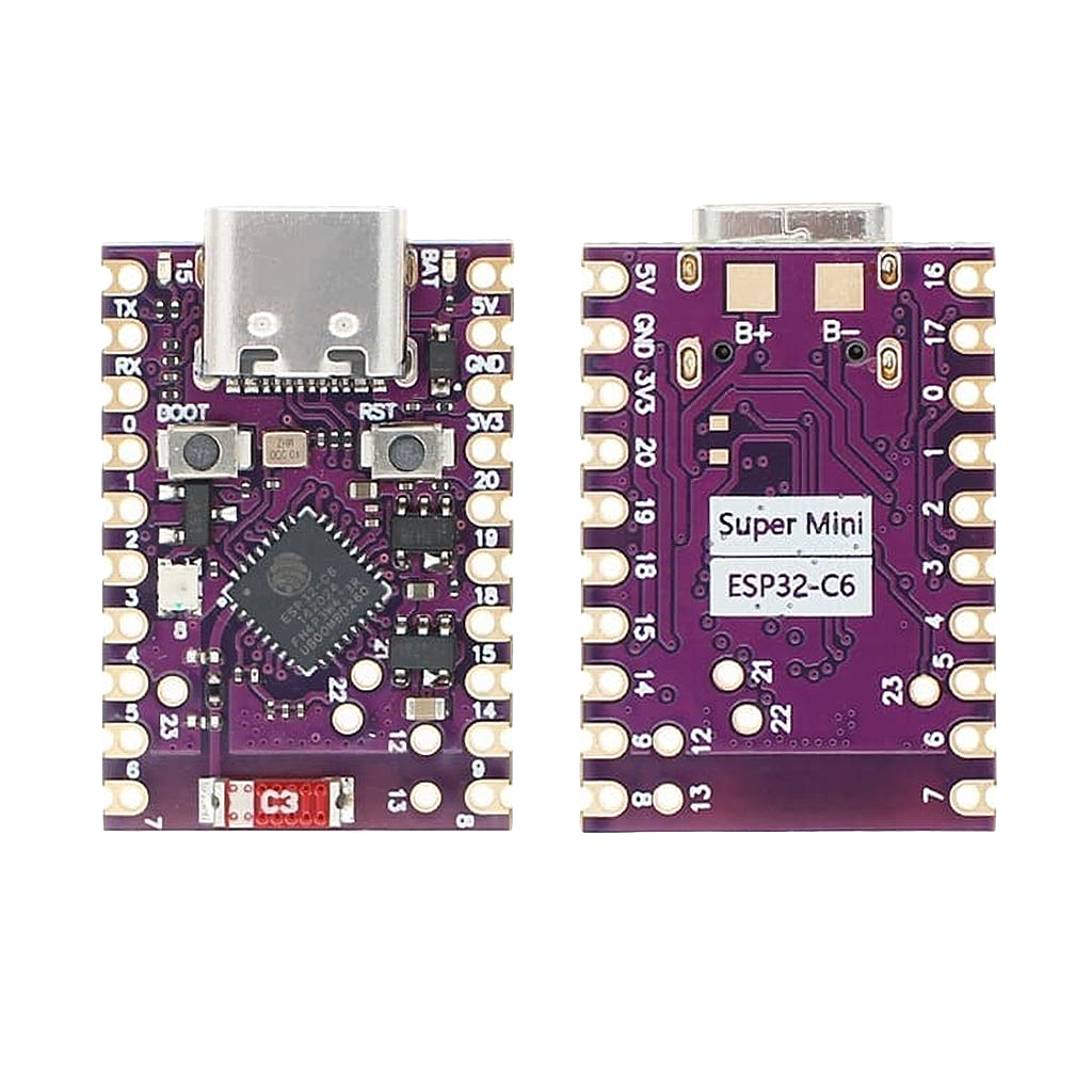
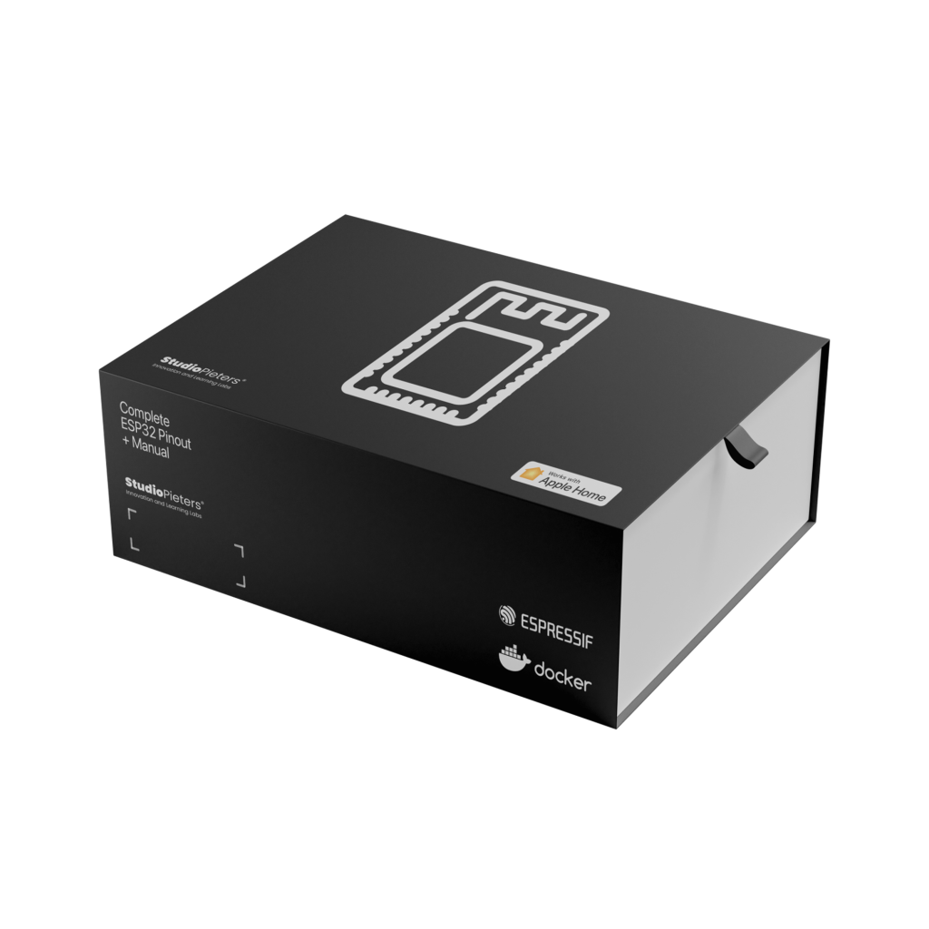
The Ultimate Guide to the ESP32-C6 SUPER MINI Pinout
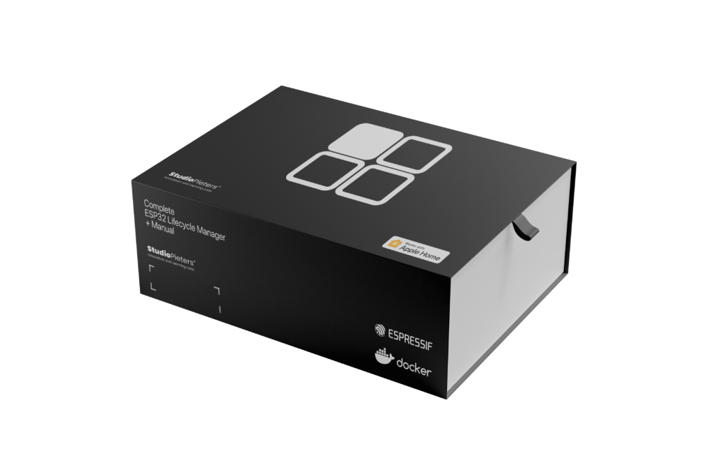
ESP32 – Lifecycle Manager V2.0
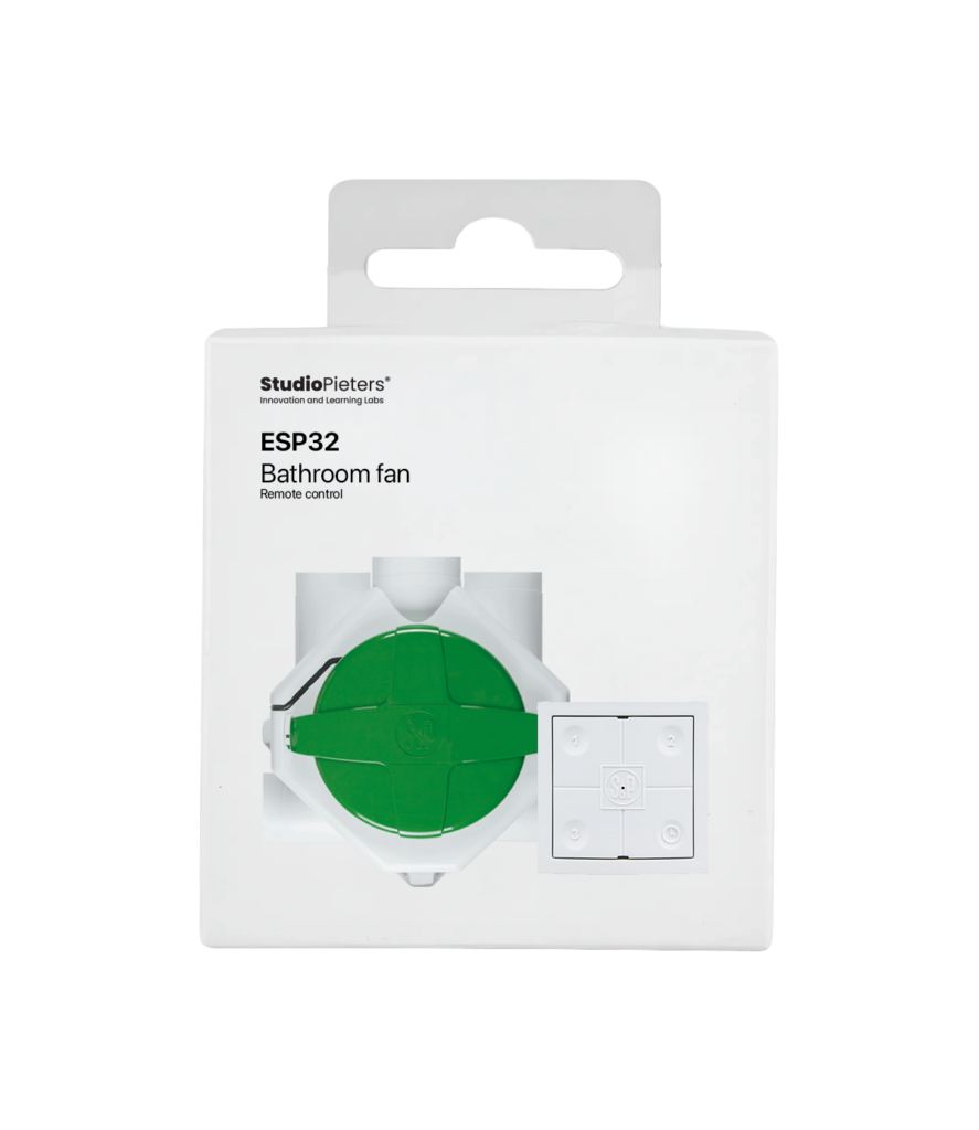
esp32 – HomeKit Bathroom Ventilation Controller
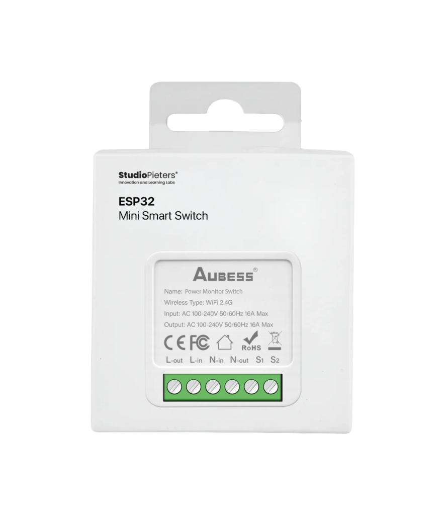
ESP32 – Mini Smart Switch with monitor
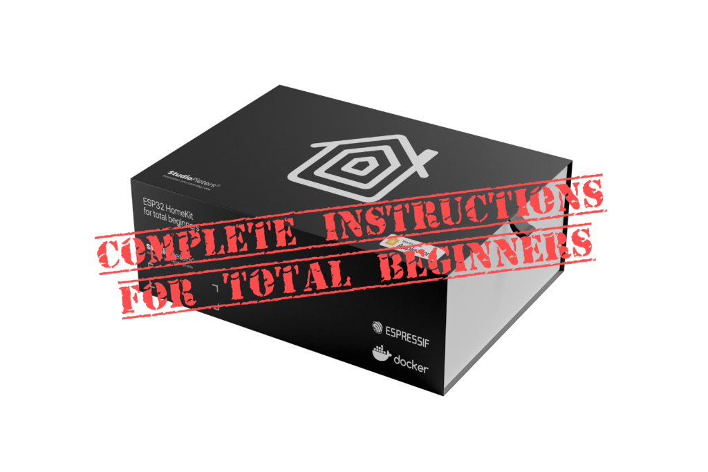
ESP32 HomeKit for TOTAL beginners

ESP32 – Power Plug with Energy Meter

esp32 – Power plug
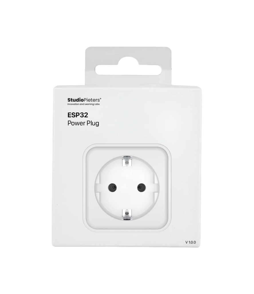
esp32 – smart connect plug
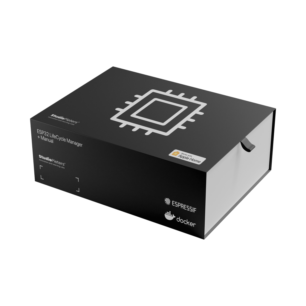
ESP32 Lifecycle Manager: Manage Your Firmware, Provisioning and Recovery in One Package

ESP32 WiFi Bootstrap: Simple Wi-Fi Provisioning with HomeKit Integration
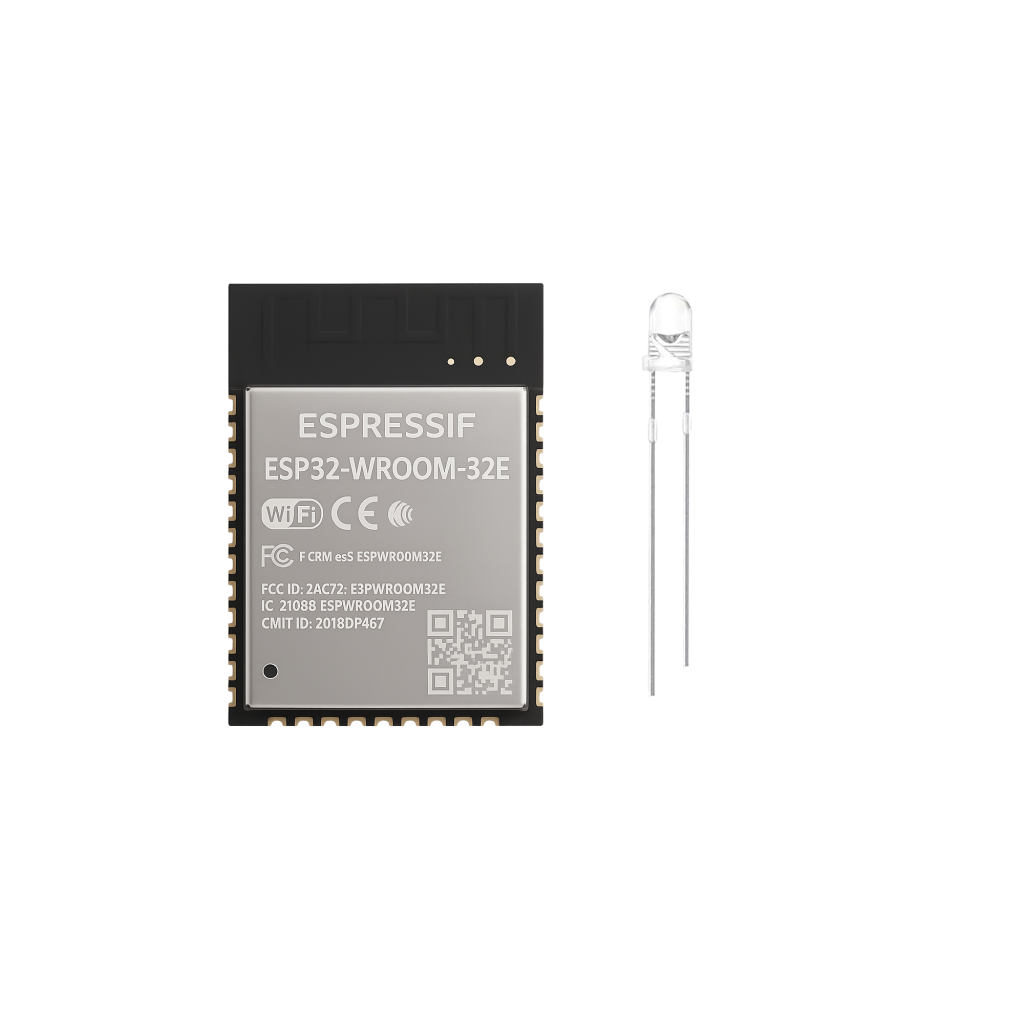
HOMEKIT LED – WITH ESP32 WROOM 32E

THE ESP-WROOM-32 PROGRAMMER
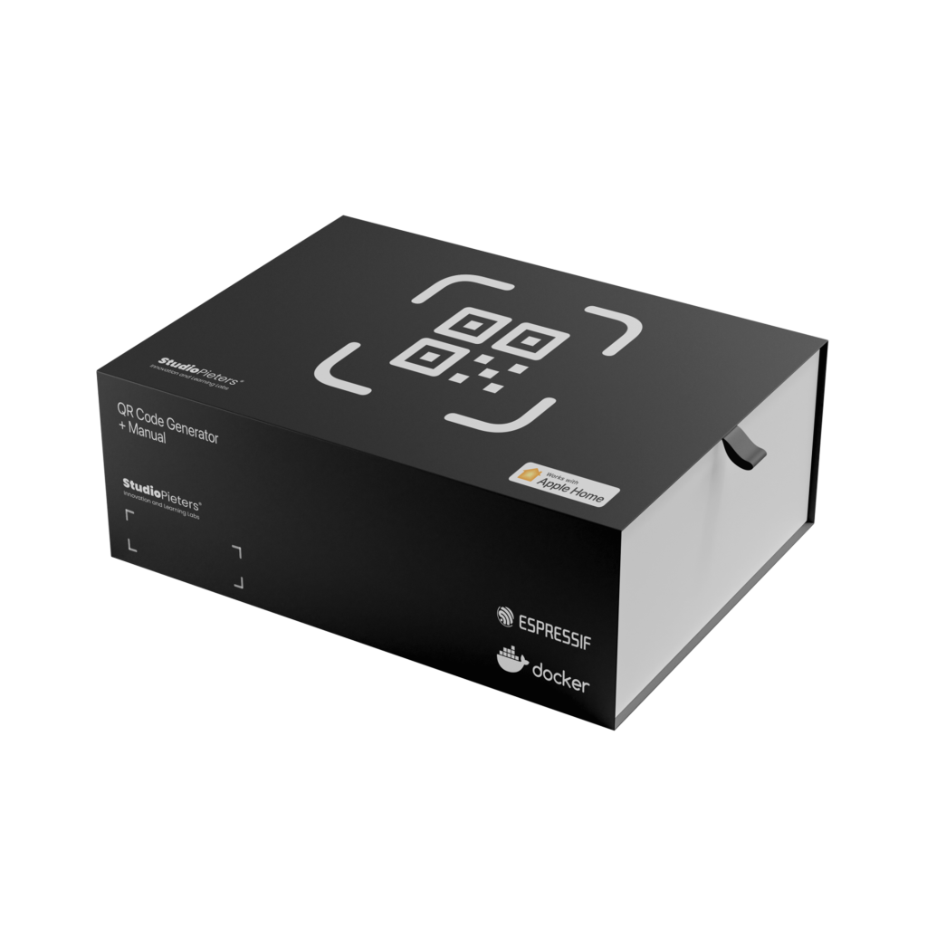
GUIDE TO ESP32 HOMEKIT QR CODES
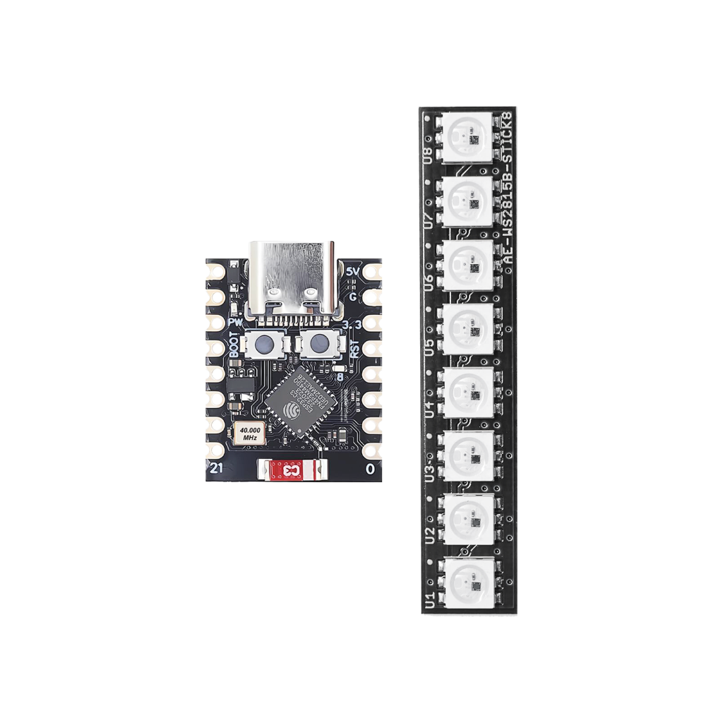
HOMEKIT NEONPixel CONTROLLER WITH ESP32-C3 SUPER MINI
ESP32 HOMEKIT DEVELOPMENT WITH ESP-IDF
- More information about Apple Homekit and the Apple Home App.
- More information about ESP32.