
Reference
MCP23017 16-Bit I/O Expander – Complete Guide
Add 16 fully-configurable GPIO pins to a pin-limited board over a two-wire I²C bus, with per-pin pull-ups and interrupt-on-change built in. This guide covers the pinout, I²C address selection, register map, ESP-IDF/Arduino code, and how it compares to the simpler PCF8574.
- Arduino
- ESP-IDF
- 9 min read
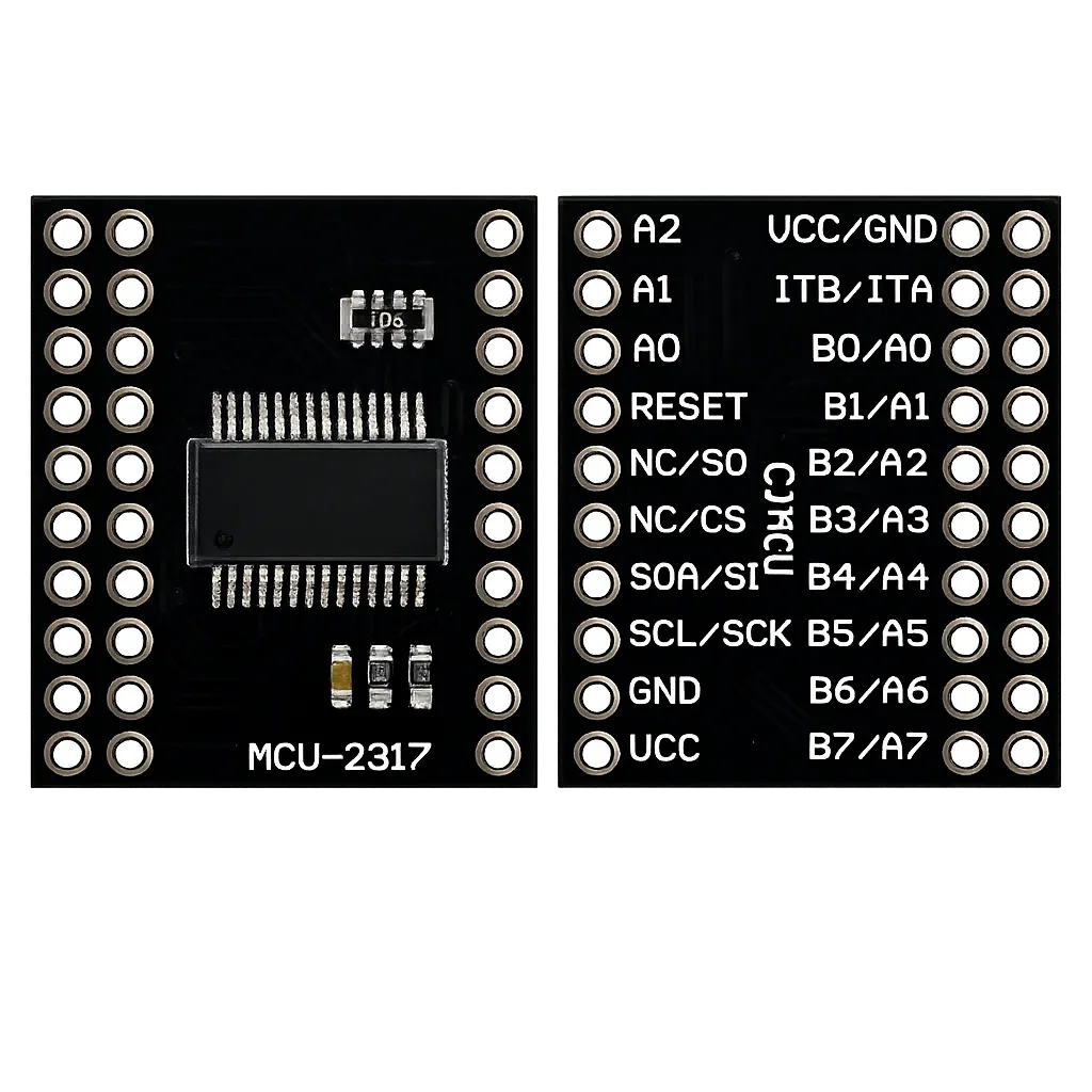
The MCP23017 16-bit I/O expander module is one of the easiest ways to add extra GPIO pins to your ESP32 project. The module is based on the MCP23017 from Microchip and gives you 16 additional, fully configurable I/O pins over a simple two-wire I²C bus. Running out of pins on a compact board like the ESP32-C6 SUPER MINI? This is the solution.
In this complete guide we cover:
- What the MCP23017 is
- Technical specifications
- Pinout (MCU-2317 / CJMCU-2317 breakout)
- I²C address selection
- GPIO overview, all 16 pins and their functions
- ESP32-C6 SUPER MINI wiring
- Register map explained
- ESP-IDF example code
- Interrupts
- MCP23017 vs PCF8574 comparison
- Practical engineering tips
What is the MCP23017?
The MCP23017 is a 16-bit I/O expander controlled over I²C. It adds two 8-bit GPIO ports, PORT A (GPA0–GPA7) and PORT B (GPB0–GPB7), to your microcontroller, each pin individually configurable as input or output.
Unlike simple shift registers, the MCP23017 includes:
- 16 bidirectional I/O pins
- Individually configurable internal 100 kΩ pull-ups
- Two interrupt outputs (INTA / INTB), mirrorable to one pin
- Interrupt-on-change with programmable compare values
- Configurable input polarity inversion
- Up to 8 devices on one I²C bus (128 extra GPIOs!)
There is also an SPI version of this chip, the MCP23S17. The MCU-2317 breakout board supports both, which is why several pins carry double labels such as SDA/SI and SCL/SCK. In this guide we use the I²C version.
Technical Specifications
| Parameter | Value |
|---|---|
| I/O pins | 16 (2 × 8-bit ports) |
| Interface | I²C (MCP23017) / SPI (MCP23S17) |
| I²C speed | 100 kHz, 400 kHz, 1.7 MHz |
| I²C address range | 0x20 – 0x27 (3 address pins) |
| Supply voltage | 1.8V – 5.5V |
| Max current per pin | 25 mA (source/sink) |
| Max total current | 125 mA per package |
| Internal pull-ups | 100 kΩ, per pin selectable |
| Interrupt outputs | INTA, INTB (mirrorable) |
| Operating temperature | -40°C to +125°C |
Power the module from 3.3V when using it with an ESP32. The chip itself tolerates 5V, but the ESP32 I²C pins are not 5V tolerant, running everything at 3.3V keeps the logic levels perfectly matched.
Pinout
The MCU-2317 (also sold as CJMCU-2317) breakout exposes the following pins:
| Pin | Description |
|---|---|
| VCC | 3.3V supply |
| GND | Ground |
| SDA/SI | I²C data (SPI MOSI on MCP23S17) |
| SCL/SCK | I²C clock (SPI clock on MCP23S17) |
| RESET | Active-low reset, must be tied HIGH |
| A0, A1, A2 | I²C address selection |
| NC/S0 | Not connected (SPI MISO on MCP23S17) |
| NC/CS | Not connected (SPI chip select on MCP23S17) |
| ITA (INTA) | Interrupt output PORT A |
| ITB (INTB) | Interrupt output PORT B |
| B0/A0 – B7/A7 | The 16 GPIO pins (GPB0–GPB7 / GPA0–GPA7) |
The small 8-pin component marked 103 on the board is a 10 kΩ resistor array providing the I²C pull-ups, so no external pull-up resistors are needed for short wire runs.
The most common mistake with this module: leaving RESET floating. The pin is active-low, and without a connection the chip randomly stays in reset and is never found on the bus. Always tie RESET to 3.3V (directly or through 10 kΩ).
I²C Address Selection
The three address pins A0, A1 and A2 set the 7-bit I²C address. This allows up to 8 modules on one bus:
| A2 | A1 | A0 | I²C Address |
|---|---|---|---|
| GND | GND | GND | 0x20 |
| GND | GND | VCC | 0x21 |
| GND | VCC | GND | 0x22 |
| GND | VCC | VCC | 0x23 |
| VCC | GND | GND | 0x24 |
| VCC | GND | VCC | 0x25 |
| VCC | VCC | GND | 0x26 |
| VCC | VCC | VCC | 0x27 |
The address pins must never float, always tie them to GND or VCC. For a single module, connect all three to GND for address 0x20.
GPIO Overview – Pins, Capabilities and Functions
Every one of the 16 GPIO pins offers the same capabilities: digital input, digital output, an individually selectable 100 kΩ internal pull-up, interrupt-on-change (routed to INTA for PORT A, INTB for PORT B), and polarity inversion.
What the GPIO pins cannot do, important to know:
| Function | Available? | Alternative |
|---|---|---|
| Digital input | Yes | — |
| Digital output | Yes | — |
| PWM | No | Use ESP32 LEDC pins or a PCA9685 |
| ADC (analog input) | No | Use ESP32 ADC pins or an ADS1115 |
| DAC | No | Use an MCP4725 |
| High-speed switching | Limited (by I²C) | Native ESP32 GPIO |
The MCP23017 is perfect for buttons, switches, relays, LEDs, rotary encoders and keypad matrices, anything that doesn’t require analog or high-frequency signals.
Connecting to the ESP32-C6 SUPER MINI
Only four wires are needed, plus the fixed connections on the module itself:
| MCP23017 Module | ESP32-C6 SUPER MINI | Wire |
|---|---|---|
| VCC | 3V3 | Red |
| GND | GND | Black |
| SDA/SI | GPIO6 | Green |
| SCL/SCK | GPIO7 | Yellow |
| RESET | 3V3 | — |
| A0, A1, A2 | GND | — |
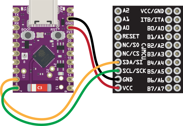
Notes: GPIO6 and GPIO7 are free, safe pins on the ESP32-C6 SUPER MINI, the I²C peripheral can be routed to any GPIO thanks to the ESP32 GPIO matrix. Avoid GPIO8: on most SUPER MINI boards the onboard RGB LED is connected there. NC/S0 and NC/CS remain unconnected (they are only used by the SPI variant). INTA/INTB are optional, connect them to a free GPIO only if you want interrupt-driven inputs.
Register Map
The MCP23017 is controlled through 22 registers. In the default mode (IOCON.BANK = 0) the A and B registers are interleaved:
| Register | Address (A/B) | Function |
|---|---|---|
| IODIRA / IODIRB | 0x00 / 0x01 | Direction: 1 = input, 0 = output |
| IPOLA / IPOLB | 0x02 / 0x03 | Input polarity inversion |
| GPINTENA / GPINTENB | 0x04 / 0x05 | Interrupt-on-change enable |
| DEFVALA / DEFVALB | 0x06 / 0x07 | Default compare value for interrupts |
| INTCONA / INTCONB | 0x08 / 0x09 | Interrupt control (compare vs. change) |
| IOCON | 0x0A / 0x0B | Configuration (mirror, bank, polarity) |
| GPPUA / GPPUB | 0x0C / 0x0D | 100 kΩ pull-up enable |
| INTFA / INTFB | 0x0E / 0x0F | Interrupt flag (which pin fired) |
| INTCAPA / INTCAPB | 0x10 / 0x11 | Pin state captured at interrupt |
| GPIOA / GPIOB | 0x12 / 0x13 | Read/write the port |
| OLATA / OLATB | 0x14 / 0x15 | Output latch |
After power-up all pins default to input. Always configure IODIRA/IODIRB first.
ESP-IDF Example Code
The example below configures GPA0 as output (blinking LED) and GPB0 as input with internal pull-up (button to GND), using the new ESP-IDF I²C master driver:
#include <stdio.h>
#include "freertos/FreeRTOS.h"
#include "freertos/task.h"
#include "driver/i2c_master.h"
#include "esp_log.h"
#define I2C_SDA_GPIO 6
#define I2C_SCL_GPIO 7
#define MCP23017_ADDR 0x20
/* MCP23017 registers (BANK = 0) */
#define REG_IODIRA 0x00
#define REG_IODIRB 0x01
#define REG_GPPUB 0x0D
#define REG_GPIOA 0x12
#define REG_GPIOB 0x13
static const char *TAG = "MCP23017";
static i2c_master_dev_handle_t mcp_handle;
static esp_err_t mcp_write_reg(uint8_t reg, uint8_t value)
{
uint8_t buf[2] = { reg, value };
return i2c_master_transmit(mcp_handle, buf, sizeof(buf), -1);
}
static esp_err_t mcp_read_reg(uint8_t reg, uint8_t *value)
{
return i2c_master_transmit_receive(mcp_handle, ®, 1, value, 1, -1);
}
void app_main(void)
{
/* I²C master bus */
i2c_master_bus_config_t bus_config = {
.i2c_port = I2C_NUM_0,
.sda_io_num = I2C_SDA_GPIO,
.scl_io_num = I2C_SCL_GPIO,
.clk_source = I2C_CLK_SRC_DEFAULT,
.glitch_ignore_cnt = 7,
.flags.enable_internal_pullup = true,
};
i2c_master_bus_handle_t bus_handle;
ESP_ERROR_CHECK(i2c_new_master_bus(&bus_config, &bus_handle));
/* MCP23017 device @ 0x20, 400 kHz */
i2c_device_config_t dev_config = {
.dev_addr_length = I2C_ADDR_BIT_LEN_7,
.device_address = MCP23017_ADDR,
.scl_speed_hz = 400000,
};
ESP_ERROR_CHECK(i2c_master_bus_add_device(bus_handle, &dev_config, &mcp_handle));
/* GPA0 = output, rest of PORT A = input */
ESP_ERROR_CHECK(mcp_write_reg(REG_IODIRA, 0xFE));
/* PORT B = all inputs */
ESP_ERROR_CHECK(mcp_write_reg(REG_IODIRB, 0xFF));
/* Enable pull-up on GPB0 */
ESP_ERROR_CHECK(mcp_write_reg(REG_GPPUB, 0x01));
ESP_LOGI(TAG, "MCP23017 initialized at 0x%02X", MCP23017_ADDR);
bool led_state = false;
while (1) {
/* Blink LED on GPA0 */
led_state = !led_state;
mcp_write_reg(REG_GPIOA, led_state ? 0x01 : 0x00);
/* Read button on GPB0 (LOW = pressed) */
uint8_t port_b;
if (mcp_read_reg(REG_GPIOB, &port_b) == ESP_OK) {
ESP_LOGI(TAG, "Button GPB0: %s",
(port_b & 0x01) ? "released" : "pressed");
}
vTaskDelay(pdMS_TO_TICKS(500));
}
}Because the MCP23017 works with plain register reads and writes, no external library is required, the ESP-IDF I²C driver is all you need.
Prefer Arduino?
With the Adafruit MCP23017 library it’s even shorter:
#include <Adafruit_MCP23X17.h>

Adafruit_MCP23X17 mcp;

void setup() {
  Wire.begin(6, 7);              // SDA = GPIO6, SCL = GPIO7
  mcp.begin_I2C(0x20);
  mcp.pinMode(0, OUTPUT);        // GPA0 → LED
  mcp.pinMode(8, INPUT_PULLUP);  // GPB0 → button
}

void loop() {
  mcp.digitalWrite(0, !mcp.digitalRead(8));
  delay(50);
}
Interrupts
Polling 16 inputs over I²C wastes bus bandwidth. The MCP23017 solves this elegantly with interrupt-on-change:
- Enable the interrupt per pin via GPINTENA/GPINTENB
- Choose the trigger: any change (INTCON = 0) or compare against DEFVAL (INTCON = 1)
- Connect INTA (PORT A) and/or INTB (PORT B) to a free ESP32 GPIO
- Set the MIRROR bit in IOCON to combine both interrupts on a single pin
- On interrupt: read INTF (which pin) and INTCAP (captured state), this also clears the interrupt
This way the ESP32 only touches the bus when something actually changes, ideal for battery-powered and event-driven designs.
MCP23017 vs PCF8574
A common alternative is the PCF8574 from NXP/Texas Instruments:
| Feature | MCP23017 | PCF8574 |
|---|---|---|
| I/O pins | 16 | 8 |
| Max I²C speed | 1.7 MHz | 100 kHz |
| Direction register | Yes | No (quasi-bidirectional) |
| Internal pull-ups | Configurable 100 kΩ | Fixed weak current source |
| Interrupt outputs | 2 (INTA/INTB) | 1 |
| Interrupt capture registers | Yes | No |
| Max devices per bus | 8 | 8 |
| Current per pin | 25 mA | ~25 mA sink only |
When to Choose the MCP23017
- You need more than 8 extra pins
- True push-pull outputs required
- Advanced interrupt handling
- Faster bus speeds
When to Choose the PCF8574
- Only a few extra pins needed
- Absolute minimum cost
- Classic LCD backpack applications
Practical Engineering Tips
1. Never Leave RESET Floating
The number one reason an MCP23017 is “not found” on the I²C bus. Tie it to 3.3V, done.
2. Run an I²C Scanner First
Before writing any application code, scan the bus. If 0x20 shows up, your wiring is correct. If not, check RESET, the address pins and your SDA/SCL wiring.
3. Watch the Current Limits
25 mA per pin sounds like plenty, but the total package limit is 125 mA. Driving 16 LEDs at 20 mA each = 320 mA = a dead chip. Use transistors or a driver IC for higher loads.
4. Keep I²C Wires Short
The onboard 10 kΩ pull-ups are fine for a breadboard. For longer runs (> 30 cm) or multiple devices, add external 4.7 kΩ pull-ups to 3.3V.
5. Use OLAT for Read-Modify-Write
When toggling individual output bits, read OLATA/OLATB (the output latch) instead of GPIOA/GPIOB. Reading GPIO returns the actual pin state, which can differ under load.
Conclusion
The MCP23017 16-bit I/O expander is a small module that solves a big problem: running out of GPIO pins. Combined with the ESP32-C6 SUPER MINI it turns a tiny board into an I/O powerhouse.
It offers 16 extra GPIO pins over just 2 wires, internal pull-ups (fewer external components), a powerful interrupt system, up to 8 modules per bus (128 extra pins), and simple register-based control with no library required.
For ESP32 + ESP-IDF developers building button matrices, relay boards or LED panels, the MCP23017 is still one of the best-value building blocks you can add to your parts drawer. See the CD74HC4067 for the analog equivalent of this problem.
Related
 Guide
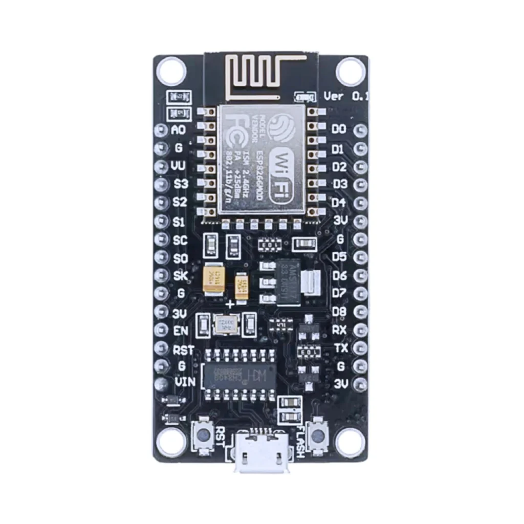
ESP8266 Pinout
The complete pin reference for the ESP8266 on NodeMCU and Wemos D1 Mini style boards: 9 usable GPIOs, one analog input, and the exact pins you can safely reuse.
Read more
Guide
ESP32-C61 Pinout
The complete pin reference for the ESP32-C61: Espressif’s budget Wi-Fi 6 chip, and the exact pins you can safely reuse.
Read more
Guide
ESP8266 Pinout
The complete pin reference for the ESP8266 on NodeMCU and Wemos D1 Mini style boards: 9 usable GPIOs, one analog input, and the exact pins you can safely reuse.
Read more
Guide
ESP32-C61 Pinout
The complete pin reference for the ESP32-C61: Espressif’s budget Wi-Fi 6 chip, and the exact pins you can safely reuse.
Read more
 Reference
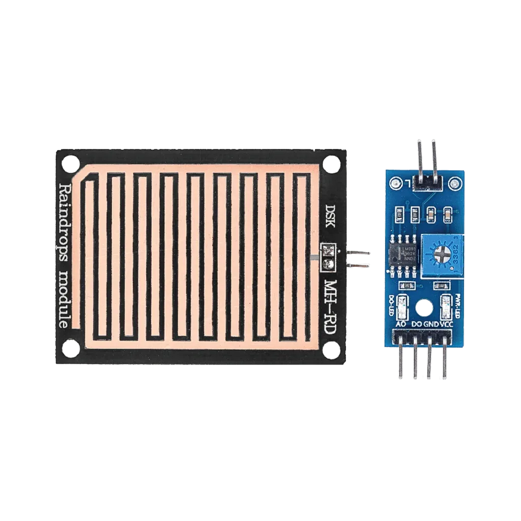
MH-RD Raindrop Detection Module
A low-cost rain sensor built from two boards: a copper-trace sensor plate and an LM393 comparator breakout. Covers the pinout, how the analog/digital outputs behave when the plate gets wet, and wiring it to an ESP32 or Arduino.
Read more
Reference
MH-RD Raindrop Detection Module
A low-cost rain sensor built from two boards: a copper-trace sensor plate and an LM393 comparator breakout. Covers the pinout, how the analog/digital outputs behave when the plate gets wet, and wiring it to an ESP32 or Arduino.
Read more
More guides
Keep building.
From ESP32 HomeKit accessories to Arduino and ATtiny reference guides, there’s more where this came from.
All guides