
Reference
CD74HC4067 16-Channel Analog Multiplexer – Complete Guide
A 16-position analog switch controlled by just 4 GPIO pins, turning one ADC input into sixteen. This guide covers the pinout, channel-select truth table, ESP32 wiring, ESP-IDF/Arduino code, and how it compares to the 74HC4051 and the ADS1115.
- ESP32
- Arduino
- 8 min read
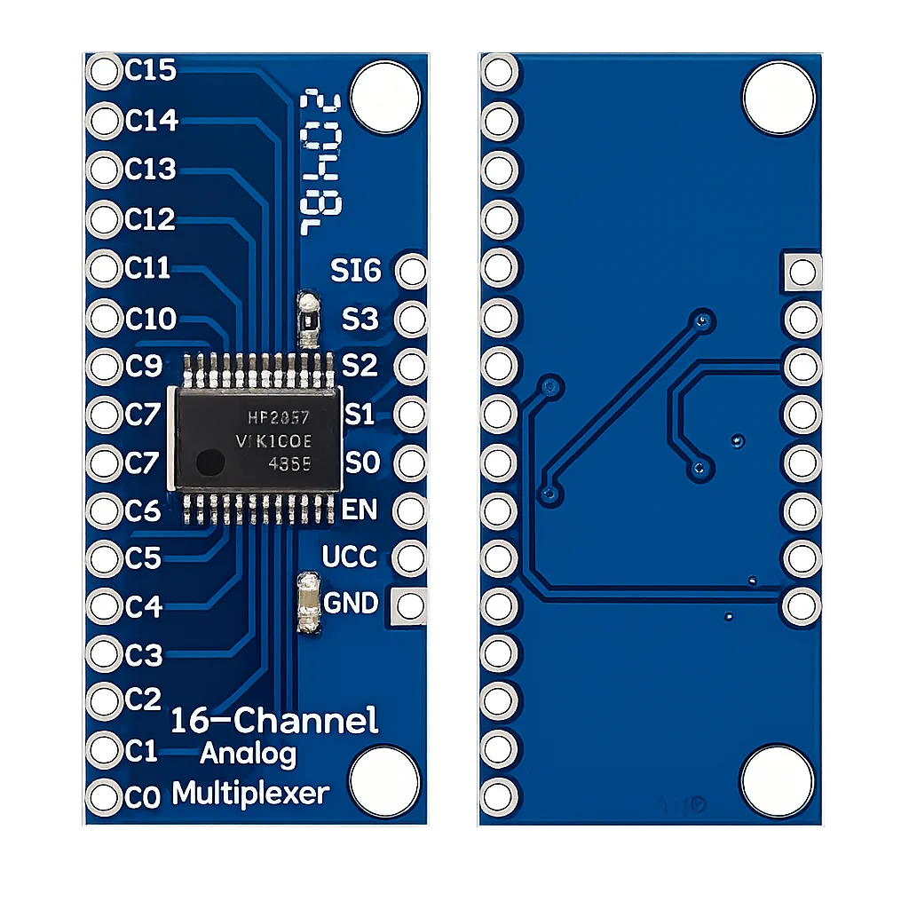
The CD74HC4067 16-channel analog multiplexer module solves the opposite problem of an I/O expander: instead of adding digital pins, it lets you read 16 analog signals through a single ADC pin. The module is based on the CD74HC4067 from Texas Instruments and is one of the cheapest and simplest ways to connect a whole array of sensors, potentiometers or buttons to a compact board like the ESP32-C6 SUPER MINI.
In this complete guide we cover:
- What the CD74HC4067 is
- Technical specifications
- Pinout
- Channel selection, truth table for all 16 channels
- ESP32-C6 SUPER MINI wiring
- How the multiplexer actually works
- ESP-IDF example code
- Using it as a demultiplexer (output mode)
- CD74HC4067 vs 74HC4051 vs ADS1115 comparison
- Practical engineering tips
What is the CD74HC4067?
The CD74HC4067 is a 16-channel analog multiplexer/demultiplexer. Think of it as a 16-position rotary switch controlled by 4 digital pins: the binary value on the select pins S0–S3 determines which of the 16 channels (C0–C15) is connected to the common signal pin (SIG).
Key properties:
- 16 channels, selected with just 4 GPIO pins
- Bidirectional, works as multiplexer (16→1) and demultiplexer (1→16)
- Passes analog and digital signals
- True analog switch: whatever voltage is on the channel appears on SIG
- Break-before-make switching (channels never short together)
- Enable pin (EN) to disconnect all channels
Because the chip is a passive switch, it doesn’t “convert” anything, your ESP32 ADC does the actual measurement. That keeps the module dirt cheap while giving you 16 analog inputs on a board that only has a handful of ADC pins.
Technical Specifications
| Parameter | Value |
|---|---|
| Channels | 16 (C0 – C15) |
| Select pins | 4 (S0 – S3) |
| Signal type | Analog and digital, bidirectional |
| Supply voltage | 2V – 6V |
| Signal voltage range | 0V to VCC |
| ON-resistance | ≈ 70 Ω (typ. @ 4.5V), higher at 3.3V |
| Max channel current | 25 mA (absolute max, stay well below) |
| Switching | Break-before-make |
| Switch-on time | < 1 µs |
| Standby current | < 1 µA |
| Operating temperature | -55°C to +125°C |
The signal voltage must stay between GND and VCC. Negative voltages or signals above the supply will damage the chip. When powered from 3.3V, never feed a 5V sensor signal into a channel.
Pinout
The common breakout board exposes the following pins:
| Pin | Description |
|---|---|
| VCC | Supply (3.3V with ESP32) |
| GND | Ground |
| SIG | Common signal pin (to ESP32 ADC) |
| S0 | Channel select bit 0 (LSB) |
| S1 | Channel select bit 1 |
| S2 | Channel select bit 2 |
| S3 | Channel select bit 3 (MSB) |
| EN | Enable, active low, LOW = enabled |
| C0 – C15 | The 16 channel pins |
Most breakout boards already pull EN to GND on the PCB, so the module is enabled by default. If you want to disable all channels (high-impedance state), drive EN HIGH from a GPIO.
Channel Selection – Truth Table
The channel is simply the binary value of S3·S2·S1·S0. This table covers all 16 channels and doubles as your reference during wiring and debugging:
| Channel | S3 | S2 | S1 | S0 | Selected Pin |
|---|---|---|---|---|---|
| 0 | 0 | 0 | 0 | 0 | C0 |
| 1 | 0 | 0 | 0 | 1 | C1 |
| 2 | 0 | 0 | 1 | 0 | C2 |
| 3 | 0 | 0 | 1 | 1 | C3 |
| 4 | 0 | 1 | 0 | 0 | C4 |
| 5 | 0 | 1 | 0 | 1 | C5 |
| 6 | 0 | 1 | 1 | 0 | C6 |
| 7 | 0 | 1 | 1 | 1 | C7 |
| 8 | 1 | 0 | 0 | 0 | C8 |
| 9 | 1 | 0 | 0 | 1 | C9 |
| 10 | 1 | 0 | 1 | 0 | C10 |
| 11 | 1 | 0 | 1 | 1 | C11 |
| 12 | 1 | 1 | 0 | 0 | C12 |
| 13 | 1 | 1 | 0 | 1 | C13 |
| 14 | 1 | 1 | 1 | 0 | C14 |
| 15 | 1 | 1 | 1 | 1 | C15 |
With EN = HIGH, no channel is connected regardless of S0–S3.
Connecting to the ESP32-C6 SUPER MINI
Six wires are all you need:
| CD74HC4067 Module | ESP32-C6 SUPER MINI | Function |
|---|---|---|
| VCC | 3V3 | Power |
| GND | GND | Ground |
| SIG | GPIO2 (ADC1_CH2) | Analog input |
| S0 | GPIO18 | Select bit 0 |
| S1 | GPIO19 | Select bit 1 |
| S2 | GPIO20 | Select bit 2 |
| S3 | GPIO21 | Select bit 3 |
| EN | GND (or free GPIO) | Enable |
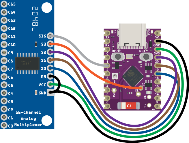
Notes: on the ESP32-C6, the ADC (ADC1) is available on GPIO0 – GPIO6. SIG must go to one of these pins, GPIO2 is a safe choice on the SUPER MINI. S0–S3 are plain digital outputs, so any free GPIO works. GPIO18–21 keeps the ADC pins free for other sensors. Avoid GPIO8 (onboard RGB LED) and GPIO9 (BOOT button).
How It Works
Reading 16 sensors becomes a simple loop:
- Write the channel number (0–15) to S0–S3
- Wait a few microseconds for the switch to settle
- Read the ADC on SIG
- Repeat for the next channel
The switch itself settles in under a microsecond, but the RC combination of the ~70 Ω ON-resistance, your wiring and the ESP32 ADC sampling capacitor needs a short settling delay, especially with high-impedance sources. A 10–50 µs delay after switching is a safe rule of thumb.
ESP-IDF Example Code
The example below scans all 16 channels once per second and prints the raw ADC values and voltages:
#include <stdio.h>
#include "freertos/FreeRTOS.h"
#include "freertos/task.h"
#include "driver/gpio.h"
#include "esp_adc/adc_oneshot.h"
#include "esp_adc/adc_cali.h"
#include "esp_adc/adc_cali_scheme.h"
#include "esp_log.h"
#include "rom/ets_sys.h"

#define MUX_S0        GPIO_NUM_18
#define MUX_S1        GPIO_NUM_19
#define MUX_S2        GPIO_NUM_20
#define MUX_S3        GPIO_NUM_21
#define MUX_SIG_ADC   ADC_CHANNEL_2   /* GPIO2 = ADC1_CH2 */

static const char *TAG = "CD74HC4067";
static adc_oneshot_unit_handle_t adc_handle;
static adc_cali_handle_t cali_handle;

static void mux_select(uint8_t channel)
{
    gpio_set_level(MUX_S0, (channel >> 0) & 1);
    gpio_set_level(MUX_S1, (channel >> 1) & 1);
    gpio_set_level(MUX_S2, (channel >> 2) & 1);
    gpio_set_level(MUX_S3, (channel >> 3) & 1);
    ets_delay_us(50);   /* settling time */
}

void app_main(void)
{
    /* Select pins as outputs */
    gpio_config_t io_conf = {
        .pin_bit_mask = (1ULL << MUX_S0) | (1ULL << MUX_S1) |
                        (1ULL << MUX_S2) | (1ULL << MUX_S3),
        .mode = GPIO_MODE_OUTPUT,
    };
    ESP_ERROR_CHECK(gpio_config(&io_conf));

    /* ADC oneshot unit */
    adc_oneshot_unit_init_cfg_t unit_cfg = {
        .unit_id = ADC_UNIT_1,
    };
    ESP_ERROR_CHECK(adc_oneshot_new_unit(&unit_cfg, &adc_handle));

    adc_oneshot_chan_cfg_t chan_cfg = {
        .atten = ADC_ATTEN_DB_12,        /* full 0 – 3.3V range */
        .bitwidth = ADC_BITWIDTH_12,
    };
    ESP_ERROR_CHECK(adc_oneshot_config_channel(adc_handle, MUX_SIG_ADC, &chan_cfg));

    /* Calibration (curve fitting on ESP32-C6) */
    adc_cali_curve_fitting_config_t cali_cfg = {
        .unit_id = ADC_UNIT_1,
        .atten = ADC_ATTEN_DB_12,
        .bitwidth = ADC_BITWIDTH_12,
    };
    ESP_ERROR_CHECK(adc_cali_create_scheme_curve_fitting(&cali_cfg, &cali_handle));

    while (1) {
        for (uint8_t ch = 0; ch < 16; ch++) {
            mux_select(ch);

            int raw, mv;
            ESP_ERROR_CHECK(adc_oneshot_read(adc_handle, MUX_SIG_ADC, &raw));
            ESP_ERROR_CHECK(adc_cali_raw_to_voltage(cali_handle, raw, &mv));

            ESP_LOGI(TAG, "C%-2d  raw: %4d  voltage: %4d mV", ch, raw, mv);
        }
        printf("n");
        vTaskDelay(pdMS_TO_TICKS(1000));
    }
}
No library, no protocol, no addresses, the CD74HC4067 is controlled with nothing more than four GPIO writes.
Prefer Arduino?
const int S0 = 18, S1 = 19, S2 = 20, S3 = 21;
const int SIG = 2;

void muxSelect(uint8_t ch) {
  digitalWrite(S0, ch & 1);
  digitalWrite(S1, (ch >> 1) & 1);
  digitalWrite(S2, (ch >> 2) & 1);
  digitalWrite(S3, (ch >> 3) & 1);
  delayMicroseconds(50);
}

void setup() {
  Serial.begin(115200);
  for (int p : {S0, S1, S2, S3}) pinMode(p, OUTPUT);
}

void loop() {
  for (uint8_t ch = 0; ch < 16; ch++) {
    muxSelect(ch);
    Serial.printf("C%d: %dn", ch, analogRead(SIG));
  }
  delay(1000);
}
Using It as a Demultiplexer (Output Mode)
Because the switch is bidirectional, you can also drive the SIG pin and route that signal to one of the 16 channels, for example to fire 16 LEDs or trigger inputs one at a time.
Keep in mind: only one channel at a time is connected, this is time-multiplexing, not 16 simultaneous outputs. The ~70 Ω ON-resistance sits in series with your load. Stay far below the 25 mA absolute maximum channel current.
For 16 real, simultaneous outputs, an MCP23017 I/O expander is the better tool, the two modules complement each other perfectly.
CD74HC4067 vs 74HC4051 vs ADS1115
| Feature | CD74HC4067 | 74HC4051 | ADS1115 |
|---|---|---|---|
| Channels | 16 | 8 | 4 |
| Interface | 4 GPIO + 1 ADC | 3 GPIO + 1 ADC | I²C |
| ADC used | ESP32 internal (12-bit) | ESP32 internal (12-bit) | Internal 16-bit |
| Accuracy | ESP32 ADC (moderate) | ESP32 ADC (moderate) | High (PGA, differential) |
| Speed | Very fast switching | Very fast switching | Max 860 SPS |
| Bidirectional | Yes | Yes | No (input only) |
| Price | Very low | Very low | Higher |
When to Choose the CD74HC4067
- Many analog sources (potentiometers, LDRs, moisture sensors)
- Moderate accuracy is fine
- Speed matters
- Minimal cost per channel
When to Choose the ADS1115
- High accuracy or small signals (load cells, precise voltages)
- Differential measurements
- You want to bypass the ESP32’s non-linear ADC entirely
Pro tip: combine them, an ADS1115 behind a CD74HC4067 gives you 16 channels of 16-bit precision.
Practical Engineering Tips
1. Give the Signal Time to Settle
Always wait 10–50 µs after changing S0–S3 before reading the ADC. With high-impedance sensors (> 100 kΩ), wait longer or add a small buffer (voltage follower op-amp).
2. Don’t Ignore the ON-Resistance
The ~70 Ω in series is irrelevant for an ADC measurement (high input impedance), but matters when sourcing current. Never use the mux for anything power-related.
3. Tie Unused Channels to GND
Floating channel pins can couple noise into your readings. Ground the channels you don’t use.
4. Discharge Ghost Voltages
The ADC sample capacitor retains charge from the previous channel. If you see readings “bleeding” from one channel into the next, read the ADC twice and discard the first sample.
5. Know the ESP32 ADC’s Limits
The ESP32-C6 ADC is non-linear near 0V and VCC. Use the ESP-IDF calibration API (as in the example) and avoid measuring signals in the extreme corners of the range when accuracy matters.
Conclusion
The CD74HC4067 16-channel analog multiplexer is the perfect companion for pin-limited boards like the ESP32-C6 SUPER MINI. For less than a euro it turns one ADC pin into sixteen.
It offers 16 analog or digital channels through 5 pins total, bidirectional operation (mux and demux), no protocol, no library, no configuration, near-zero power consumption, and seamless pairing with the MCP23017 for digital I/O.
If your project has more sensors than pins, the CD74HC4067 should be the first module you reach for.
Related
 Guide
ESP8266-01 Pinout
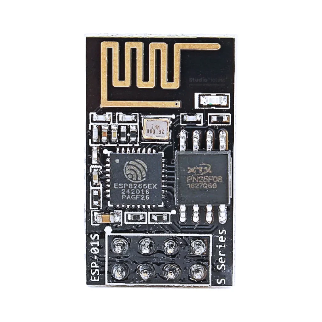
The complete pin reference for the ESP8266-01 breakout: just 8 pins, only 2 usable GPIOs, and no onboard USB, so wiring it up needs a bit more care than a dev board.
Read more
Guide
ESP8266-01 Pinout
The complete pin reference for the ESP8266-01 breakout: just 8 pins, only 2 usable GPIOs, and no onboard USB, so wiring it up needs a bit more care than a dev board.
Read more
 Reference
HC-SR04 Ultrasonic Distance Sensor
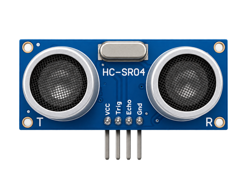
A cheap trigger/echo distance sensor for parking aids, water-level monitors and obstacle-avoiding robots. Covers the 5V echo pin that can damage a 3.3V-only ESP32 GPIO, and the safe ways to level-shift it.
Read more
Reference
HC-SR04 Ultrasonic Distance Sensor
A cheap trigger/echo distance sensor for parking aids, water-level monitors and obstacle-avoiding robots. Covers the 5V echo pin that can damage a 3.3V-only ESP32 GPIO, and the safe ways to level-shift it.
Read more
 Reference
MPU6050 Accelerometer + Gyroscope Complete Guide
The MPU6050 packs a 3-axis accelerometer and 3-axis gyroscope on one die with an onboard motion-fusion processor, for around the price of a single sensor. This guide covers its real I2C addressing, pinout, and wiring one to an ESP32.
Read more
Reference
MPU6050 Accelerometer + Gyroscope Complete Guide
The MPU6050 packs a 3-axis accelerometer and 3-axis gyroscope on one die with an onboard motion-fusion processor, for around the price of a single sensor. This guide covers its real I2C addressing, pinout, and wiring one to an ESP32.
Read more
More guides
Keep building.
From ESP32 HomeKit accessories to Arduino and ATtiny reference guides, there’s more where this came from.
All guides