One thing that was still missing for me on the Raspberry Pi®, was the inclusion of some kind of power switch or Powerunit ®. Considering how many common Raspberry Pi® projects could make use of this functionality. Still, we’ve lived with this problem with the old version for a long time, and there are plenty of switch products out there to get around it. Today I’ve been Designing the Powerunit͘® to switch my the Raspberry Pi® On and Off.
Powerunit ®
Well, you don’t. You also don’t need a Raspberry Pi® , a iPhone, or even that candy bar you’re eating as you read this. A switch (Powerunit ®) for the Raspberry Pi® is a “nice thing to have”.

It means you don’t have to plug and unplug the micro USB power cable each time you use your Pi – hopefully increasing the life of that delicate connection. It also saves you having to bend down and unplug that Raspberry Pi® media center, making the experience that whole lot slicker.

There’s also a learning element here – this example requires full assembly, and there’s only a few parts to solder. I personally enjoy this side of projects, but less confident ‘makers’ may opt for a ready-made solution. So it’s up to you if you want to add a switch (Powerunit ®) to your Raspberry Pi® – but I certainly want one!
Hardware
When the Raspberry Pi® is in the shutdown state, it still uses a considerable amount of power and leaves the power LED lit, so it is therefore not particularly suitable to certain applications. That’s why I’m looking for a way to create a fully functional On/Off power switch. This solution includes an On switch, a Off switch, and a reset switch, as well as an LED as power indicator. The solution connects in-line with your 5V power supply.
Components
1 x ATTINY85
1 x 220Ω resistor
2 x 10KΩ resistor
2 x Momentary switch
1 x BC548 (NPN transistor)
1 x 1N4001 Diode
1 x Omron G5V-1-5DC Relay
1 x 3mm LED
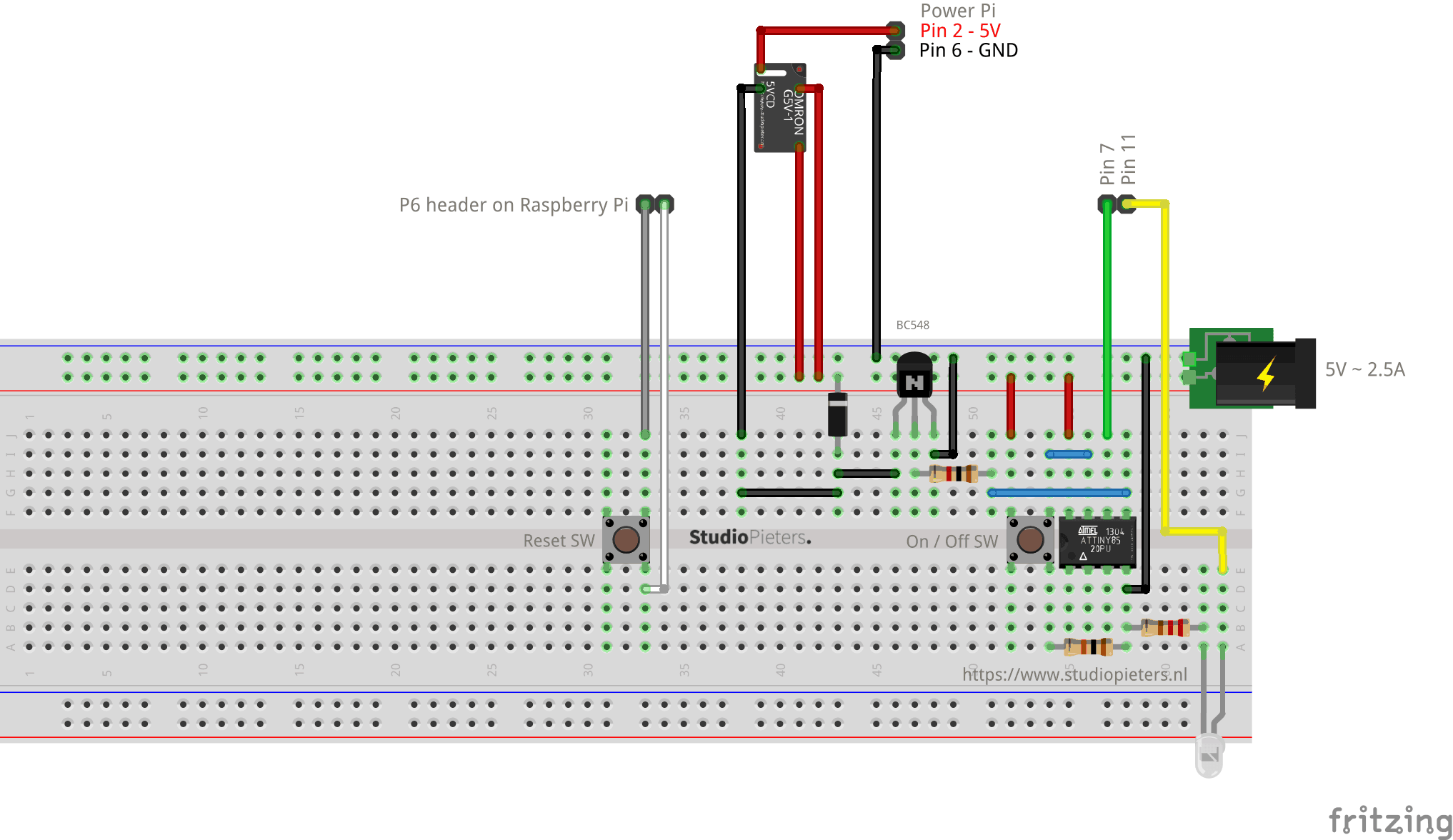
The Powerunit ® circuit
When the relay is in the off state, but 5V is supplied to the input, the voltage does not travels through the relay. But will only power the ATTiny85. The ATTiny85 is Programmed as a “simple” On/Of Switch (Powerunit ®). When you press the On/Off button It will set the relay to High. Once the output is high , it turns on the BC548 transistor, which connects one end of the relay coil to ground. The relay is instantly activated. This causes power to be supplied to the output.

When you press the On/Off button It will set the relay to High. But It also Sets Pin 7 of the Raspberry Pi® to High. As long as this pin stay’s High. noting will happen and the Raspberry Pi® stays on. When you press the On/Off button It will not set the relay to Low. Only Pin 7 of the raspberry will be set to Low. Once the Pin 7 is Low on the Raspberry Pi® , a Python™ script starts running, shutting down your Raspberry Pi® Safely. There’s a delay from 30 Seconds build in to give the Raspberry Pi® time to shutdown safely. When these 30 seconds have run out, it turns off the BC548 transistor, which disconnects one end of the relay coil to ground. The relay is instantly deactivated. This causes power to be cutoff to the output.
Then there’s a LED connected to Pin 11 from your Raspberry Pi® (Optional). This indicates weather the power is on or off. The Reset button is already integrated on your Raspberry Pi® as P6, you only need to connect a switch, to be able to reset your Raspberry Pi® , when necessary.
Code Examples
To turn on and of the power there’s some code needed for the safe shutdown functionality to work correctly.
The Powerunit ® causes the script to initiate the shutdown.
Attiny85 Code
Open Arduino IDE and paste in the code from beneath. A later section describes how to program the Attiny85.
/* Project name: Powerunit®
   Project URI:  https://www.studiopieters.nl/raspberry-pi-power-unit
   Description: Powerunit® - Atmel® ATTiny85 Software package
   Version: 3.9.2
   License: MIT - Copyright 2018 StudioPieters. (https://opensource.org/licenses/MIT)
*/

int RelaisPin = 0;                // ATTINY85/13A (PB0 / Physical Pin 5)
int PinSeven = 1;                 // ATTINY85/13A (PB1 / Physical Pin 6)
int ButtonPin = 2;                // ATTINY85/13A (PB2 / Physical Pin 7)


boolean OldRelaisState = LOW;     // variable to hold the OLD Relais state
boolean NewRelaisState = LOW;     // variable to hold the NEW Relais state
boolean Relaisstatus = LOW;       // variable to hold the Relais state

void setup()
{
  pinMode(RelaisPin, OUTPUT);     // Set Relaispin as Output
  digitalWrite(RelaisPin, LOW);   // Set Relaispin to LOW

  pinMode(PinSeven, OUTPUT);      // Set PinSeven as Output
  digitalWrite(PinSeven, LOW);    // Set PinSeven to LOW

  pinMode(ButtonPin, INPUT);      // Set Buttonpin as Input
}

void loop()
{
  NewRelaisState = digitalRead(ButtonPin);

  if ( NewRelaisState != OldRelaisState )
  {
    if ( NewRelaisState == HIGH )
    {
      if ( Relaisstatus == LOW ) {
        digitalWrite(RelaisPin, HIGH);    // Set Relaispin to HIGH
        digitalWrite(PinSeven, HIGH);     // Set PinSeven to HIGH
        Relaisstatus = HIGH;
      }
      else                    {
        digitalWrite(PinSeven, LOW);      // Set PinSeven to LOW
        delay(30000);                    // wait for 30 Seconds to shutdown all services on your Pi
        digitalWrite(RelaisPin, LOW);     // Set Relaispin to LOW
        Relaisstatus = LOW;
      }
    }
    OldRelaisState = NewRelaisState;
  }
}
programming the Attiny85
Let’s connect the necessary pins together on both boards.

1 x Arduino Nano (or any Arduino board will do)
1 x ATtiny85
6 x Jumper Wires
1 x Electrolytic Capacitor – 10µF ~ 25V
We need to connect the MOSI, MISO and SCK pins of both boards together (refer to the IC pin out), and Digital Pin 10 of the Arduino Nano to P5 of the ATTiny85.
Connect the following (I am using an Arduino Nano, so you have to take note the necessary pins of the board you are using when using it as an ISP).
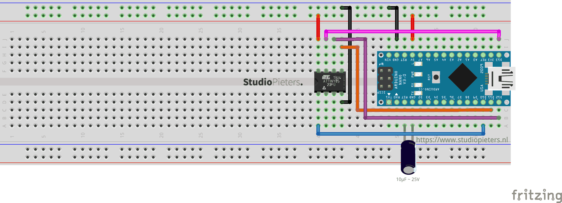
Add a 10uF capacitor between RESET and GND in arduino. This is to avoid Arduino Nano from being auto reset when we upload the program to attiny85. If you are using a electrolytic capacitor make sure the anode goes in GND of Arduino Nano.
| Arduino Nano | ATTINY85 | |
| MOSI | Digital Pin 11 | PB0 (Chip Pin 5) |
| MISO | Digital Pin 12 | PB1 (Chip Pin 6) |
| SCL | Digital Pin 13 | PB2 (Chip Pin 7) |
| RESET | Digital Pin 10 | PB5 (Chip Pin 1) |
| VCC | VCC (5V) | VCC (Chip Pin 8) |
| GND | GND | GND (Any GND pin) |
There are two things we need to set up to successfully program the ATTiny85.
Installing the ATTint Boards
Open the Arduino IDE Software then go to Arduino > Preferences. You will see Additional Boards Manager URLs. Add this link there, by pressing the rightmost icon. and ad this link:
Press OK (then another OK to exit from Preferences).
Now, go to Tools > Board > Boards Manager. Type attiny in the search field, and you should see attiny by David A. Mellis. Click it (attiny by David A. Mellis) and install the board. Now, you should see attiny boards from the list when you go to Tool > Boards. Scroll down to verify that the board is indeed installed.
Arduino as ISP
Attach the Arduino Nano to your computer. Go to File > Examples > ArduinoISP, and click on Arduino ISP. Then go to Tools > Boards and select Arduino Nano (or your preferred board). Go to Tools > Port and select the port where your board is connected to. Upload the ArduinoISP sketch to your Arduino Nano (or your preferred board) by going to Sketch > Upload. At this stage, your Arduino Nano is ready to be used as a programmer.
Note: In some cases you need to select Processor : “ATMega328P (Old Bootloader)”
Uploading the sketch
Make sure that the connections are as stated as described here above. Open the program / sketch you want upload to your ATtiny85. Go to Tool and setup the following.
| Board: | “ATtiny25/45/85” |
| Processor: | “ATtiny85” |
| Clock: | “Internal 8 MHz” |
| Port: | Select the port where your board is connected to. |
Then make sure Arduino as ISP is selected under Tools -> Programmer. By default the ATtiny85 runs at 1MHz. To make it to run at 8MHz select Tools -> Burn Bootloader. Now open the Attiny85 Code from my github here and upload. Your Attiny85 is now ready for use.

Python Code
In Python™ you have two ways to implement this solution – with a while loop or using interrupts. Open Atom text editor and paste in the code from beneath. A later section describes how to load a Python™ file during the boot process.
Powerunit.py
# Project name: Powerunit ®
# Project URI:  https://www.studiopieters.nl/raspberry-pi-power-unit
# Description: Powerunit® - Raspberry Pi® Software package
# Version: 1.0.1
# License: MIT - Copyright 2018 StudioPieters. (https://opensource.org/licenses/MIT)


#!/usr/bin/env python

# Import the modules to send commands to the system and access GPIO pins
from subprocess import call
import RPi.GPIO as GPIO
from time import sleep

# Map pin seven and eight on the  Power.Unit͘  PCB to chosen pins on the Raspberry Pi header
# The PCB numbering is a legacy with the original design of the board
PinSeven = 7
           PinEleven = 11
                       GPIO.setmode(GPIO.BOARD) # Set pin numbering to board numbering
                       GPIO.setup(PinSeven, GPIO.IN) # Set up PinSeven as an input
                       GPIO.setup(PinEleven, GPIO.OUT, initial = 1) # Setup PinEleven as output

                       while (GPIO.input(PinSeven) == True): # While button not pressed
                           GPIO.wait_for_edge(PinSeven, GPIO.RISING) # Wait for a rising edge on PinSeven
                           sleep(0.1); # Sleep 100ms to avoid triggering a shutdown when a spike occured


  if (GPIO.input(PinSeven) == True):
    GPIO.output(PinEleven, 0) # Bring down PinEleven so that the LED turn off
    call('poweroff', shell = False) # Initiate OS Poweroff
else:
      call('reboot', shell = False) # Initiate OS Reboot
Obviously the file name Powerunit.py that we used above can be whatever you want it to be, and the folder names and locations are all up to you as wel. You just need to make sure that you maintain these throughout the above locations to make sure this code will function correctly on boot. In the above example we have used physical pin 7 on the GPIO header, which as you can see corresponds to the 4th pin from the right, on the top row (when looking down on the Pi from above, with the RCA video connector socket facing towards you).
| Fuction | Name | Pin | Pin | Name | Fuction | ||
| Power | 3.3V | 1 | ● | ● | 2 | 5V | Power |
| SDA1 I2C | GPIO2 | 3 | ● | ● | 4 | 5V | Power |
| SCL1 I2C | GPIO3 | 5 | ● | ● | 6 | Ground | |
| GPIO_GCLK | GPIO4 | 7 | ● | ● | 8 | GPIO14 | UART0_TXD |
| Ground | 9 | ● | ● | 10 | GPIO15 | UART0_RXD | |
| GPIO17 | 11 | ● | ● | 12 | GPIO18 | PCM_CLK | |
| GPIO27 | 13 | ● | ● | 14 | Ground | ||
| GPIO22 | 15 | ● | ● | 16 | GPIO23 | ||
| Power | 3.3V | 17 | ● | ● | 18 | GPIO24 | |
| SPI0_MOSI | GPIO10 | 19 | ● | ● | 20 | Ground | |
| SPI0_MISO | GPIO9 | 21 | ● | ● | 22 | GPIO25 | |
| SPI0_SCLK | GPIO11 | 23 | ● | ● | 24 | GPIO8 | SPI0_CE0_N |
| Ground | 25 | ● | ● | 26 | GPIO7 | SPI0_CE1_N | |
| I2C ID EEPROM | ID_SD | 27 | ● | ● | 28 | ID_SC | I2C ID EEPROM |
| GPIO5 | 29 | ● | ● | 30 | Ground | ||
| GPIO6 | 31 | ● | ● | 32 | GPIO12 | ||
| GPIO13 | 33 | ● | ● | 34 | Ground | ||
| GPIO19 | 35 | ● | ● | 36 | GPIO16 | ||
| GPIO26 | 37 | ● | ● | 38 | GPIO20 | ||
| Ground | 39 | ● | ● | 40 | GPIO21 |
You can change this to use any different GPIO pin, we just chose pin 7 as it is next to physical pin 11 which is the required pin to use for the automatic power supply switching without any additional code. It is additionally possible to add some code to the above to change to a pin other than physical pin 11 for the main automatic power off functionality.
Under-Voltage
If you use the Powerunit͘® with the Raspberry Pi® 3 you may experience under-voltage issues and unexpected power off. In order to solve the under voltage problem it is advisable to use shorter power cable. 15-30 cm with a thickness of 22 AWG should solve the issue. These types of cable are generally the ones used for phone charging and should be easily found in various shops.
Now that my Powerunit ® Project – Prototyping phase is done I can go further with the Powerunit® Project – Software phase of the project in the upcoming blog post.
REFERENCE
Raspberry Pi® (2019), The Raspberry Pi is a tiny and affordable computer that you can use to learn programming through fun, practical projects, https://www.raspberrypi.orgPython™ (2019 )Python is a programming language that lets you work quickly and integrate systems more effectively, https://www.python.org/ PiSupply (DEC 5 2017), Pi-Supply-Switch, Pi Supply Switch On/Off Switch for Raspberry Pi, https://github.com/PiSupply/Pi-Supply-Switch