
HomeKit
ESP8266 HomeKit Button Switch
A small ESP8266 that appears in the Home app as a HomeKit switch, to turn another accessory on or off. A test setup with an ESP-01, three buttons and an FTDI adapter.
- ESP8266
- HomeKit
- 3 min read
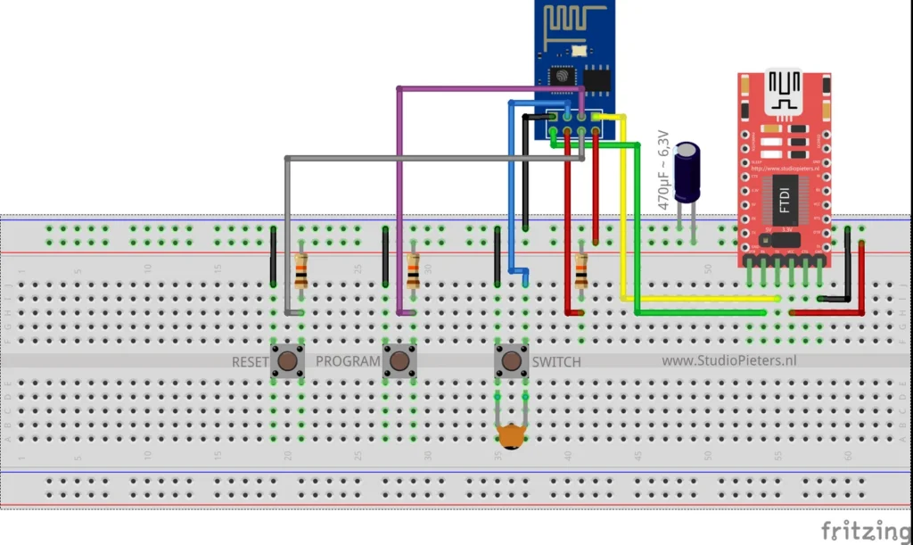
A small ESP8266 that shows up in the Apple Home app as a HomeKit switch. It is on or off, and that is what makes it useful: switch it from the Home app, or use it as a trigger to turn another accessory on or off through an automation.
This is a test setup, built to check that the code and the hardware work together.
What it does
| Feature | Details |
|---|---|
| HomeKit switch | Appears in the Home app with a plain on and off state |
| Physical button | A SWITCH button on the device |
| Use | Switch another accessory on or off, for example from an automation |
| Updates | Over the air, through Life Cycle Manager 2 |
| No cloud | Control stays on your own network |
Hardware
| Component | Notes |
|---|---|
| ESP8266 ESP-01 module | 8 pins, only two usable GPIOs. See the ESP8266-01 pinout |
| 3 push buttons | Labelled RESET, PROGRAM and SWITCH on the diagram |
| USB-serial (FTDI) adapter | For flashing, and for power in this test setup. Set it to 3.3 V logic |
| 470 µF capacitor, 6.3 V | Across the supply, as drawn. Needed for stable operation when the module is powered from the FTDI adapter |
| Resistors and a small ceramic capacitor | Pull-ups on the buttons and a ceramic capacitor across the SWITCH button, as drawn |
In this test setup the module is powered from the FTDI adapter. Place the 470 µF capacitor across the supply as drawn, because the setup needs it to run stably. Powering from the FTDI adapter works for testing, but it is not recommended for long-term use.
Wiring
The Fritzing diagram at the top of this page shows the whole build on a breadboard. Reading the wires against the ESP-01 pinout gives this assignment:
| Part | ESP-01 pin | Purpose |
|---|---|---|
| SWITCH button | GPIO2 | The HomeKit switch input |
| PROGRAM button | GPIO0 | Pulls GPIO0 low, which puts the module in flash mode |
| RESET button | RST | Resets the module |
| FTDI adapter | TXD and RXD | Serial connection, crossed over to the adapter |
| 3.3 V supply | VCC and CH_PD | CH_PD is tied high to keep the chip enabled |
These pins are read from the diagram and are not listed in the repository text, so check them against the diagram before you build. The ESP-01 needs GPIO0 and GPIO2 high at reset for a normal start, which is why the buttons have pull-up resistors. Use an FTDI adapter set to 3.3 V, because a 5 V adapter can damage the module.
Flash and install
The installation is the same as for the other ESP8266 HomeKit accessories on this site. The firmware runs on ESP-Open-RTOS with Life Cycle Manager 2, which sets up the WiFi and installs updates over the air. The three boot files (rboot.bin, blank_config.bin and otaboot.bin) are in the repository, and the full steps, from installing esptool to flashing, joining the LCM- WiFi network and pairing, are in ESP8266 HomeKit Blinds.
In the portal, use these values:
| Field | Value |
|---|---|
| OTA repository | AchimPieters/ESP8266-HomeKit-Button |
| OTA binary file | main.bin |
When the installation is done, scan the QR code the device generates in the Home app to add it.
Firmware release
| Version | Date | Files |
|---|---|---|
| 0.0.1 | 9 May 2019 | main.bin |
The firmware is published as a binary in the release.
Good to know
- This is a test setup and not a finished product.
- The HomeKit Accessory Protocol specification the firmware follows is the non-commercial version, for accessories you build yourself and do not distribute or sell.
- The repository has the boot files, the diagram and the MIT licence, but no source code.
Everything is in the ESP8266-HomeKit-Button repository on GitHub.
Related
 HomeKit
ESP32 Mini Smart Switch with Monitor
For the hobby developer who wants full control over their smart hardware, the Aubess Power Monitor Switch is an excellent starting point.
Read more
HomeKit
ESP32 Mini Smart Switch with Monitor
For the hobby developer who wants full control over their smart hardware, the Aubess Power Monitor Switch is an excellent starting point.
Read more
 HomeKit
ESP32-CAM as a HomeKit Camera
A proof of concept: the AI-Thinker ESP32-CAM as a camera accessory in the Apple Home app, with a still image and a stream that is not smooth.
Read more
HomeKit
ESP32-CAM as a HomeKit Camera
A proof of concept: the AI-Thinker ESP32-CAM as a camera accessory in the Apple Home app, with a still image and a stream that is not smooth.
Read more
 HomeKit
ESP8266 HomeKit White LED Strip
A standard white LED strip that Apple Home switches on and off through an ESP8266 and a relay, installed with Life Cycle Manager 2.
Read more
HomeKit
ESP8266 HomeKit White LED Strip
A standard white LED strip that Apple Home switches on and off through an ESP8266 and a relay, installed with Life Cycle Manager 2.
Read more
More HomeKit
Keep building.
Switches, sensors, plugs and blinds: more accessories that you build yourself and add to the Home app.
All HomeKit