If you’re a maker, designer or an engineer, chances are you’ll need to make a custom enclosure at some point. This might be a simple container to keep small items organized or a fully functional prototype as I made here in the past. With Autodesk® Fusion 360 software and a desktop 3D printer, you can create a custom snap fit enclosure.
Prepare Your Custom Enclosure Design
For this project, we’re going to make a case, for fictive a single board computer. This tutorial uses AutoCAD Fusion 360 because of its popularity in product design and engineering, but you can use a similar 3D design software. First, use digital calipers or a ruler to measure your electronic component in real life. You can then start enclosure designs by accurately reverse-engineering the PCB, measuring the board size, the location of mounting holes, and any ports or plugs that will need to be accessed through the enclosure.
You might want to simply measure the overall maximum dimensions as a box, but it’s essential to know exactly where the main features are so that you can accommodate them. In AutoCAD Fusion 360, reproduce these measurements as a grouping of basic boxes in a single part file.
The Bottom Enclosure
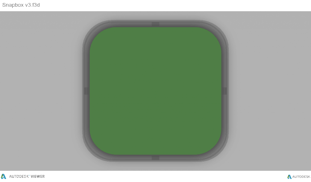
In AutoCAD Fusion 360, the snap fit enclosure is best designed as an assembly, with each half of the enclosure modelled as a separate part. Starting with the base half of the enclosure as a new part, the first important decision is to determine how much of a tolerance to have between the perimeter of the PCB and the enclosure. 3D printers are highly accurate, so you can tighten the tolerance to 0.5 mm without much risk. An FDM printer may warp your design and lift it off of the print plate, so you should allow a larger tolerance of 1.5-2 mm to ensure that the PCB will still fit inside even if the walls are somewhat distorted.Add space between the perimeter of your electronic component and the enclosure. Build the walls of the bottom enclosure in your 3D model.
Optional: Your next step is to start cutting away the openings for the ports. One common mistake is that you will only cut away just enough material to expose the port connection, be it a USB or HDMI, without taking into account that many cables around the male connector can be quite bulky and need to reach into your enclosure to connect to the port (especially if the port is set in from the edge of the PCB, farther away from the enclosure). So it’s best to be generous with the port openings. An extra 1 mm all the way around is a good starting point. Add extruded cuts and cut-outs to the bottom enclosure to fit ports.
The Top Enclosure
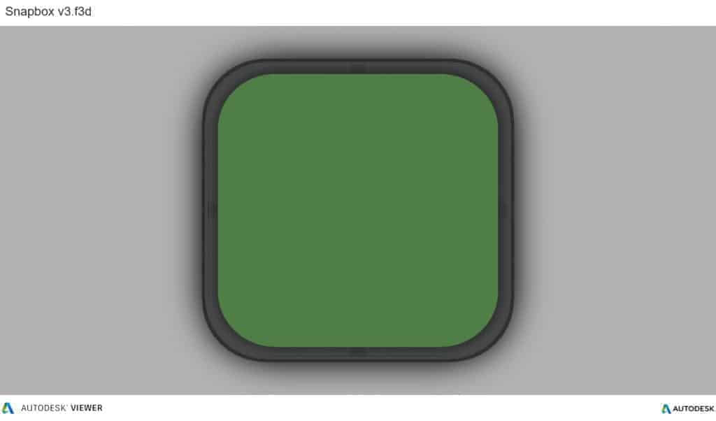
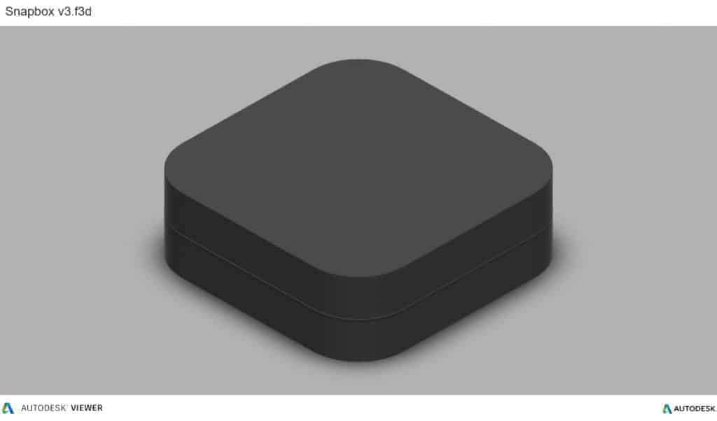
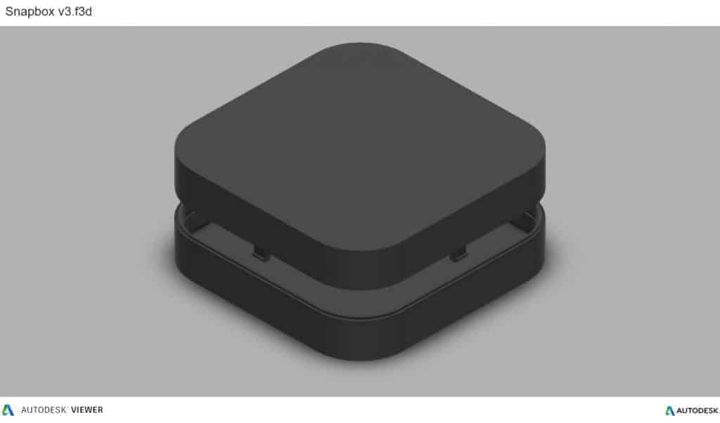
In general, the top snap fit enclosure mirrors the geometry of the bottom snap fit enclosure.Now that you’ve completed the bottom t enclosure, the top section is easy. The above image shows the effect of the parting line running around the perimeter between the two enclosure halves. The top snap fit enclosure has had the same treatment of cut details to accommodate some of the taller ports, as well as the addition of material to close off some of the gaps left by the bottom enclosure. We also added an optional sunken middle section.
The Snap Detail
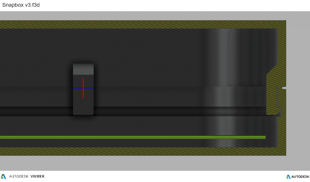
With a basic internal cantilever snap, you can lengthen the amount of plastic engaging into the snap for a stronger lock. There are many designs for snaps, but we opted for a basic internal cantilever. Above you can see the main details for the snap design, which is exactly the same on both sides of the snap fit enclosure. Depending on the space you have to work with, you can lengthen the amount of plastic engaging into the snap cavity to create a stronger lock. Ours is only 1.2 mm, but 2 mm or more would be much more secure. In this particular design, the pins on the PCB take up a lot of room, so the lock is designed to just squeeze in while providing enough force to hold the snap fit enclosure together. The snap detail is extruded 20 mm long, which adds to the strength. This sectioned exploded view shows the snap details on each side.
Add Final Details To Your snap fit Enclosure
While this might be enough detail for your project, a few added features can bring your enclosure to life. For this design, you can add some text and details like the SD card location. You can included the a logo as a visual feature, but we also recommend to provide ventilation on the top since some boards can heat up. Plus, these details reduce the amount of material used.
Finally, a couple of grip details where the snaps are located helps indicate where to press your fingers to open the snap fit enclosure. The final design includes your unique features along with the snap fit snap fit enclosure, ready to be 3D printed!