
Reference
PCA9685 16-Channel PWM/Servo Driver
A 16-channel, 12-bit I2C PWM driver that turns two ESP32 wires into enough hardware-generated outputs for a whole rack of servos or an LED array. Covers the pinout, address selection, register map, and the safe way to power servos without browning out the board.
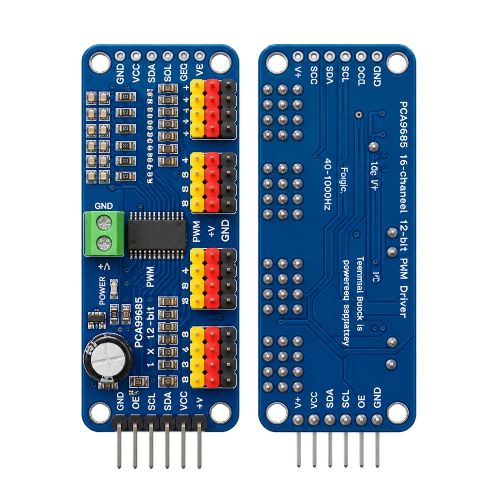
The PCA9685 16-channel PWM/servo driver module is one of the easiest ways to add PWM, LED dimming and servo control to your ESP32 project. The module is based on the PCA9685 from NXP and gives you 16 independent, 12-bit PWM outputs over a simple two-wire I²C bus. The MCP23017 gave you 16 extra digital pins — but it can’t do PWM. This module is the answer.
In this complete guide we cover:
- What the PCA9685 is
- Technical specifications
- Pinout (16-channel breakout)
- I²C address selection
- PWM channel overview – all 16 outputs and their functions
- ESP32-C6 SUPER MINI wiring
- Register map explained
- Setting the PWM frequency (the prescale formula)
- ESP-IDF example code (LED dimming + servo)
- Arduino example code
- Powering servos the right way
- PCA9685 vs ESP32 native LEDC comparison
- Practical engineering tips
What is the PCA9685?
The PCA9685 is a 16-channel, 12-bit PWM controller driven over I²C. Each of its 16 outputs can be set independently to any duty cycle from 0 to 4095 (12-bit resolution), which makes it ideal for driving LEDs, RGB strips and — most famously — hobby servos.
Unlike bit-banging PWM from your microcontroller, the PCA9685 generates all 16 signals in hardware. Once you write a value, the chip keeps toggling the pin on its own — your ESP32 does nothing until you change it.
Key features:
- 16 independent PWM channels
- 12-bit resolution per channel (4096 steps)
- One programmable frequency for all channels (≈24 Hz – 1526 Hz)
- 25 MHz internal oscillator, or an external clock up to 50 MHz
- Configurable totem-pole or open-drain outputs
- Output Enable (OE) pin to switch all channels off at once
- Up to 62 devices on one I²C bus (992 PWM channels!)
- Built-in software reset and “All Call” addressing
Every channel has its own ON and OFF timing registers, so you can not only set the duty cycle but also phase-shift each output — a neat trick to spread inrush current when driving many LEDs.
Technical Specifications
| Parameter | Value |
|---|---|
| PWM channels | 16 |
| Resolution | 12-bit (4096 steps) per channel |
| Interface | I²C (Fast-mode Plus, up to 1 MHz) |
| I²C address range | 0x40 – 0x7F (6 address pins) |
| Logic supply (VCC) | 2.3V – 5.5V |
| Output supply (V+) | Up to 6V (servo/LED power rail) |
| Current per output | 25 mA sink / 10 mA source |
| PWM frequency | ≈24 Hz – 1526 Hz (shared) |
| Internal oscillator | 25 MHz (external clock up to 50 MHz) |
| Output type | Totem-pole or open-drain (OUTDRV) |
| Operating temperature | -40°C to +85°C |
⚠️ Power the logic side (VCC) from 3.3V when using it with an ESP32 so the I²C levels match. The servo/LED side (V+) needs its own supply — never try to run servos from the ESP32’s 3.3V pin (see Powering servos below).
Pinout
The standard 16-channel breakout exposes a header on each side plus 16 three-pin output groups:
| Pin | Description |
|---|---|
| VCC | 3.3V logic supply |
| GND | Ground (shared with V+ ground) |
| SDA | I²C data |
| SCL | I²C clock |
| OE | Output enable — active-low, tie to GND to run |
| V+ | Servo/LED power rail (screw terminal, up to 6V) |
| A0 – A5 | I²C address selection (solder jumpers) |
| PWM0 – PWM15 | The 16 PWM outputs (each with its own V+ and GND) |
Each output group has three pins in the classic servo order: PWM signal, V+, GND — so a servo plugs straight in without any adapter.
⚠️ The OE pin is active-low. On many clone boards it is left floating, which can cause all outputs to switch off unpredictably. Tie OE to GND to keep the outputs permanently enabled, or route it to a spare ESP32 GPIO if you want a hardware “all-off” switch.
I²C Address Selection
The six solder-jumper pads A0–A5 set the 7-bit I²C address, giving a base of 0x40 with nothing bridged. Bridging a pad adds its bit:
| Bridged pads | I²C Address |
|---|---|
| none | 0x40 |
| A0 | 0x41 |
| A1 | 0x42 |
| A0 + A1 | 0x43 |
| A2 | 0x44 |
| A5 + A4 + A3 | 0x78 |
| all (A0–A5) | 0x7F |
That allows a theoretical 62 modules on one bus — up to 992 PWM channels. Two addresses are reserved by default: 0x70 (LED All Call) and the software-reset address 0x00, so avoid those.
⚠️ For a single module, bridge nothing and use the default address 0x40.
PWM Channel Overview – Capabilities and Functions
Every one of the 16 outputs is identical. This table shows what each channel can and cannot do:
| Function | Available? | Notes |
|---|---|---|
| Hardware PWM output | ✅ | 12-bit, independent duty cycle |
| LED dimming | ✅ | 0–4095 brightness steps |
| Hobby servo control | ✅ | At 50 Hz, ~150–600 counts |
| Per-channel phase shift | ✅ | Separate ON and OFF registers |
| Independent frequency per pin | ❌ | All channels share one frequency |
| Analog output (true DAC) | ❌ | Use an [MCP4725] for a real DAC |
| Analog input (ADC) | ❌ | Use an ADS1115 |
| High current per pin | ❌ | 25 mA sink — use a driver for more |
The PCA9685 is perfect for servo arms, pan/tilt rigs, robotic legs, LED walls, RGB(W) lighting and motorised blinds — anything that needs many smooth, hands-off PWM signals at the same frequency.
Connecting to the ESP32-C6 SUPER MINI
Only four signal wires are needed, plus a separate power feed for the servo rail:
| PCA9685 Module | ESP32-C6 SUPER MINI | Wire |
|---|---|---|
| VCC | 3V3 | Red |
| GND | GND | Black |
| SDA | GPIO6 | Green |
| SCL | GPIO7 | Yellow |
| OE | GND | — |
| V+ | External 5V supply | — |
| GND (V+) | External supply GND | — |
Notes:
- GPIO6 and GPIO7 are free, safe pins on the ESP32-C6 SUPER MINI — the I²C peripheral can be routed to any GPIO thanks to the ESP32 GPIO matrix.
- Avoid GPIO8: on most SUPER MINI boards the onboard RGB LED is connected there.
- The ESP32 ground and the external 5V ground must be connected together (common ground) or the signals will not be referenced correctly.
- The onboard I²C pull-ups on the breakout are fine for short runs — no external resistors needed.
Register Map
The PCA9685 is controlled through a small set of registers. The most important ones:
| Register | Address | Function |
|---|---|---|
| MODE1 | 0x00 | Sleep, restart, auto-increment, All Call |
| MODE2 | 0x01 | Output type, invert, output-change timing |
| LED0_ON_L | 0x06 | Channel 0 “ON” time, low byte |
| LED0_ON_H | 0x07 | Channel 0 “ON” time, high byte |
| LED0_OFF_L | 0x08 | Channel 0 “OFF” time, low byte |
| LED0_OFF_H | 0x09 | Channel 0 “OFF” time, high byte |
| LEDn… | 0x06 + 4n | Four registers per channel (n = 0…15) |
| ALL_LED_ON_L…H | 0xFA – 0xFB | Set all channels’ ON time at once |
| ALL_LED_OFF_L…H | 0xFC – 0xFD | Set all channels’ OFF time at once |
| PRE_SCALE | 0xFE | PWM frequency prescaler |
Each channel uses four registers: a 12-bit ON count and a 12-bit OFF count. For simple duty-cycle control you set ON = 0 and OFF = your value (0–4095). To phase-shift a channel, give it a non-zero ON value.
⚠️ Enable the auto-increment (AI) bit in MODE1 (0x20) so you can write all four LED registers in one I²C transaction. It also makes the code much shorter.
Setting the PWM Frequency
All 16 channels share one frequency, set by the PRE_SCALE register. The formula:
prescale = round( 25 000 000 / (4096 × frequency) ) − 1
For 50 Hz (standard hobby servos):
prescale = round( 25 000 000 / (4096 × 50) ) − 1 = 121 (0x79)
⚠️ The PRE_SCALE register can only be written while the chip is asleep. The sequence is: set the SLEEP bit → write PRE_SCALE → clear SLEEP → wait 500 µs → set the RESTART bit. The example code below does exactly this.
ESP-IDF Example Code
The example configures the module for 50 Hz, dims an LED on channel 0 and sweeps a servo on channel 1, using the new ESP-IDF I²C master driver:
#include <stdio.h>
#include <math.h>
#include "freertos/FreeRTOS.h"
#include "freertos/task.h"
#include "driver/i2c_master.h"
#include "esp_log.h"
#define I2C_SDA_GPIO 6
#define I2C_SCL_GPIO 7
#define PCA9685_ADDR 0x40
/* PCA9685 registers */
#define REG_MODE1 0x00
#define REG_MODE2 0x01
#define REG_LED0_ON_L 0x06
#define REG_PRESCALE 0xFE
/* MODE1 bits */
#define MODE1_RESTART 0x80
#define MODE1_AI 0x20
#define MODE1_SLEEP 0x10
static const char *TAG = "PCA9685";
static i2c_master_dev_handle_t pca;
static esp_err_t write_reg(uint8_t reg, uint8_t val)
{
uint8_t buf[2] = { reg, val };
return i2c_master_transmit(pca, buf, sizeof(buf), -1);
}
static esp_err_t read_reg(uint8_t reg, uint8_t *val)
{
return i2c_master_transmit_receive(pca, ®, 1, val, 1, -1);
}
/* Set one channel: on = 0..4095 start, off = 0..4095 stop */
static void set_pwm(uint8_t ch, uint16_t on, uint16_t off)
{
uint8_t buf[5] = {
(uint8_t)(REG_LED0_ON_L + 4 * ch),
(uint8_t)(on & 0xFF), (uint8_t)(on >> 8),
(uint8_t)(off & 0xFF), (uint8_t)(off >> 8),
};
i2c_master_transmit(pca, buf, sizeof(buf), -1);
}
static void set_frequency(float hz)
{
uint8_t prescale = (uint8_t)(roundf(25000000.0f / (4096.0f * hz)) - 1);
uint8_t old_mode;
read_reg(REG_MODE1, &old_mode);
write_reg(REG_MODE1, (old_mode & ~MODE1_RESTART) | MODE1_SLEEP); /* sleep */
write_reg(REG_PRESCALE, prescale); /* set freq */
write_reg(REG_MODE1, old_mode); /* wake */
vTaskDelay(pdMS_TO_TICKS(1));
write_reg(REG_MODE1, old_mode | MODE1_RESTART | MODE1_AI); /* restart + AI */
}
void app_main(void)
{
i2c_master_bus_config_t bus_config = {
.i2c_port = I2C_NUM_0,
.sda_io_num = I2C_SDA_GPIO,
.scl_io_num = I2C_SCL_GPIO,
.clk_source = I2C_CLK_SRC_DEFAULT,
.glitch_ignore_cnt = 7,
.flags.enable_internal_pullup = true,
};
i2c_master_bus_handle_t bus;
ESP_ERROR_CHECK(i2c_new_master_bus(&bus_config, &bus));
i2c_device_config_t dev_config = {
.dev_addr_length = I2C_ADDR_BIT_LEN_7,
.device_address = PCA9685_ADDR,
.scl_speed_hz = 400000,
};
ESP_ERROR_CHECK(i2c_master_bus_add_device(bus, &dev_config, &pca));
set_frequency(50.0f); /* 50 Hz for servos */
ESP_LOGI(TAG, "PCA9685 ready at 0x%02X", PCA9685_ADDR);
int brightness = 0, step = 64;
while (1) {
/* Channel 0: breathing LED */
brightness += step;
if (brightness >= 4095 || brightness <= 0) step = -step;
set_pwm(0, 0, brightness);
/* Channel 1: sweep servo between ~1 ms and ~2 ms */
for (int pos = 150; pos <= 600; pos += 15) {
set_pwm(1, 0, pos);
vTaskDelay(pdMS_TO_TICKS(20));
}
for (int pos = 600; pos >= 150; pos -= 15) {
set_pwm(1, 0, pos);
vTaskDelay(pdMS_TO_TICKS(20));
}
}
}
Because the PCA9685 works with plain register reads and writes, no external library is required — the ESP-IDF I²C driver is all you need.
Prefer Arduino?
With the Adafruit PWM Servo Driver library it’s much shorter:
#include <Adafruit_PWMServoDriver.h>

Adafruit_PWMServoDriver pca = Adafruit_PWMServoDriver(0x40);

void setup() {
  Wire.begin(6, 7);          // SDA = GPIO6, SCL = GPIO7
  pca.begin();
  pca.setPWMFreq(50);        // 50 Hz for servos
}

void loop() {
  pca.setPWM(1, 0, 150);     // servo ~1 ms
  delay(500);
  pca.setPWM(1, 0, 600);     // servo ~2 ms
  delay(500);
}
Powering Servos the Right Way
This is the single most common mistake with the PCA9685, so it gets its own section.
⚠️ Never power servos from the ESP32. A single small servo can draw 500 mA – 1 A during a stall, far more than the ESP32’s 3.3V regulator can deliver. Doing so causes brownouts, random reboots and I²C errors.
Do this instead:
- Feed the V+ rail from a dedicated 5V supply sized for your servos (a couple of amps for several servos).
- Connect the VCC logic pin to the ESP32’s 3.3V — the logic side draws only a few milliamps.
- Tie all grounds together: ESP32 GND, PCA9685 GND and the 5V supply GND.
- Add a large electrolytic capacitor (470–1000 µF) across V+ and GND close to the module to absorb servo current spikes.
PCA9685 vs ESP32 Native LEDC
The ESP32 already has hardware PWM through its LEDC peripheral, so when do you need a PCA9685?
| Feature | PCA9685 | ESP32 LEDC (native) |
|---|---|---|
| PWM channels | 16 per module | 6–8 (varies per ESP32 model) |
| Resolution | 12-bit (fixed) | Up to 14-bit |
| Interface | I²C (2 wires) | Direct GPIO |
| Uses ESP32 GPIOs | Only 2 (SDA/SCL) | One GPIO per channel |
| Independent frequency | No (shared) | Yes (per timer) |
| Devices chainable | Up to 62 (992 ch.) | One MCU |
| Extra hardware needed | Yes (the module) | No |
When to Choose the PCA9685
- You need more channels than the ESP32 has PWM pins
- You’re driving many servos or a large LED array
- You want to keep ESP32 GPIOs free
- You need to daisy-chain many outputs across boards
When to Choose Native LEDC
- You only need a handful of PWM outputs
- You want per-channel frequency control
- You want zero extra components and the lowest latency
Practical Engineering Tips
1. Use a Separate Servo Supply
The number one cause of “my ESP32 keeps rebooting” — servos brown out the board. Give V+ its own 5V rail and share the ground.
2. Run an I²C Scanner First
Before any application code, scan the bus. If 0x40 shows up, your wiring is correct. If not, check VCC, GND, SDA/SCL and the OE pin.
3. Calibrate Your Servos
The 150–600 count range is a safe default, but cheap servos vary. Find each servo’s real minimum and maximum experimentally to get the full sweep without buzzing at the end stops.
4. Add a Bulk Capacitor
A 470–1000 µF capacitor across V+ smooths the current spikes when several servos move at once and keeps the whole system stable.
5. Phase-Shift Big LED Arrays
Driving all 16 LED channels on at the same instant creates a large inrush. Give each channel a different ON value so they turn on at slightly different moments — the supply barely notices.
Conclusion
The PCA9685 16-channel PWM/servo driver is a small module that solves a big problem: not enough PWM. Combined with the ESP32-C6 SUPER MINI it turns two I²C wires into 16 rock-steady, hardware-generated PWM outputs.
It offers:
- 16 independent 12-bit PWM channels over just 2 wires
- Hardware PWM — the ESP32 stays free to do other work
- Perfect for servos, LED dimming and RGB lighting
- Up to 62 modules per bus: 992 PWM channels
- Simple register-based control, no library required
Where the MCP23017 adds digital pins and the CD74HC4067 adds analog inputs, the PCA9685 completes the set by adding analog-style outputs. For any ESP32 project involving motion or light, it’s one of the best-value building blocks you can add to your parts drawer.
Related
 Reference
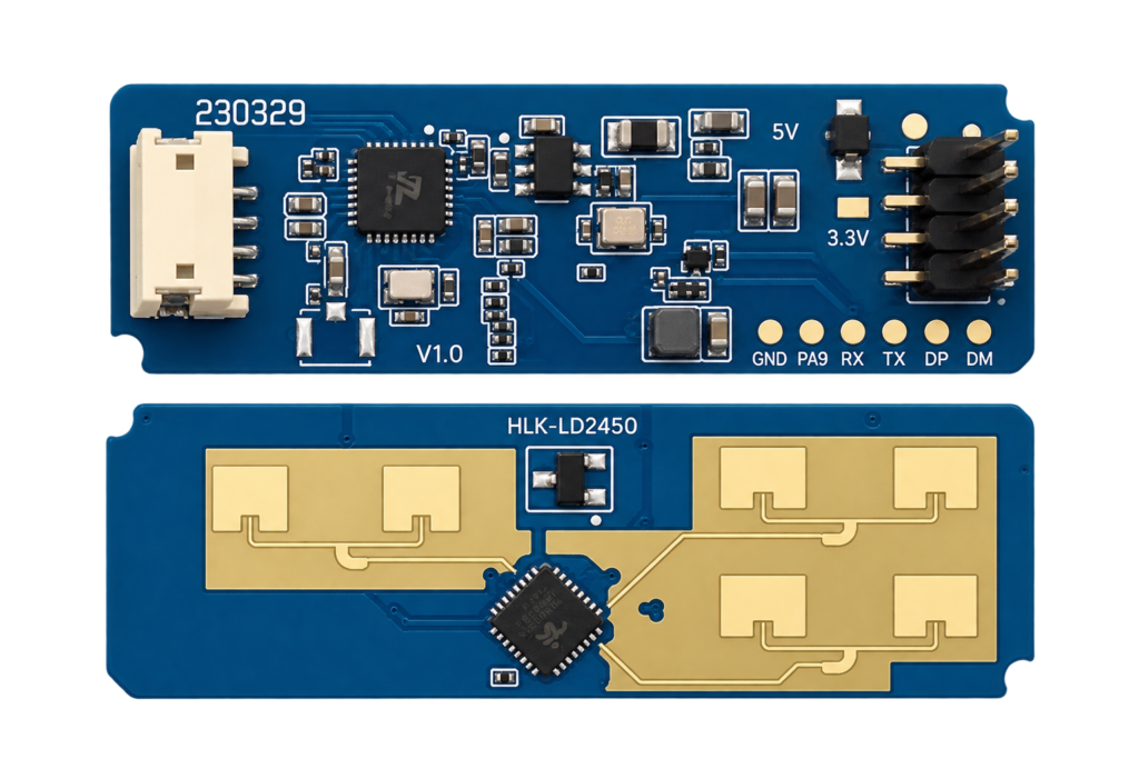
The Complete Guide to the HLK-LD2450 24GHz Multi-Target Tracking Radar Module
The LD2450 is Hi-Link's multi-target mmWave radar: where the already-published LD2410 only tells you someone is present, the LD2450 tracks up to three people at once with real X/Y position and speed. This guide covers its real UART protocol, wiring, and when you actually need position tracking over simple presence.
Read more
Reference
The Complete Guide to the HLK-LD2450 24GHz Multi-Target Tracking Radar Module
The LD2450 is Hi-Link's multi-target mmWave radar: where the already-published LD2410 only tells you someone is present, the LD2450 tracks up to three people at once with real X/Y position and speed. This guide covers its real UART protocol, wiring, and when you actually need position tracking over simple presence.
Read more
 Reference
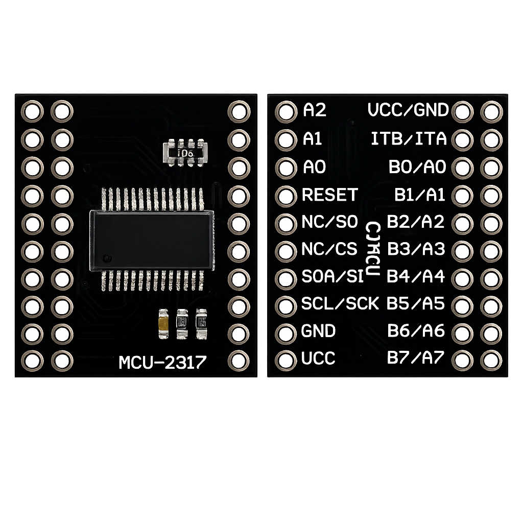
MCP23017 16-Bit I/O Expander – Complete Guide
Add 16 fully-configurable GPIO pins to a pin-limited board over a two-wire I²C bus, with per-pin pull-ups and interrupt-on-change built in. This guide covers the pinout, I²C address selection, register map, ESP-IDF/Arduino code, and how it compares to the simpler PCF8574.
Read more
Reference
MCP23017 16-Bit I/O Expander – Complete Guide
Add 16 fully-configurable GPIO pins to a pin-limited board over a two-wire I²C bus, with per-pin pull-ups and interrupt-on-change built in. This guide covers the pinout, I²C address selection, register map, ESP-IDF/Arduino code, and how it compares to the simpler PCF8574.
Read more
 Guide
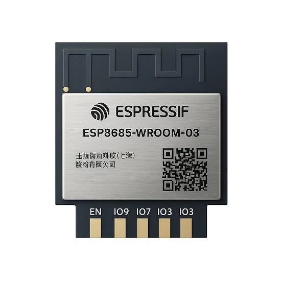
ESP8685-WROOM-03 Pinout
The complete pin reference for the ESP8685-WROOM-03 module: Espressif’s enhanced ESP32-C2-family chip in an 11-pin package, and the exact pins you can safely reuse.
Read more
Guide
ESP8685-WROOM-03 Pinout
The complete pin reference for the ESP8685-WROOM-03 module: Espressif’s enhanced ESP32-C2-family chip in an 11-pin package, and the exact pins you can safely reuse.
Read more
More guides
Keep building.
From ESP32 HomeKit accessories to Arduino and ATtiny reference guides, there’s more where this came from.
All guides