
Reference
NodeMCU-ESP32-C2 Pinout
The pin reference for the NodeMCU-style ESP32-C2 development board: the ESP8684-WROOM-02 module, its exposed GPIOs, and how to flash it over USB-C.
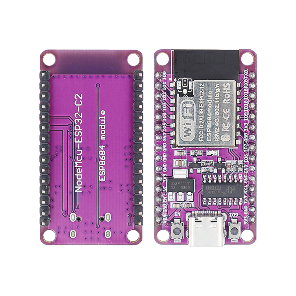
The NodeMCU-ESP32-C2 is a NodeMCU-style development board built around Espressif’s ESP8684-WROOM-02 module, a different, larger module than the bare ESPC2-02 module this site already documents. Same ESP32-C2 chip underneath, more pins broken out and a full USB-C/CH340C programming circuit on board. This guide covers this specific development board: its GPIO layout, communication pins, and how to flash it.
System-on-chip and module
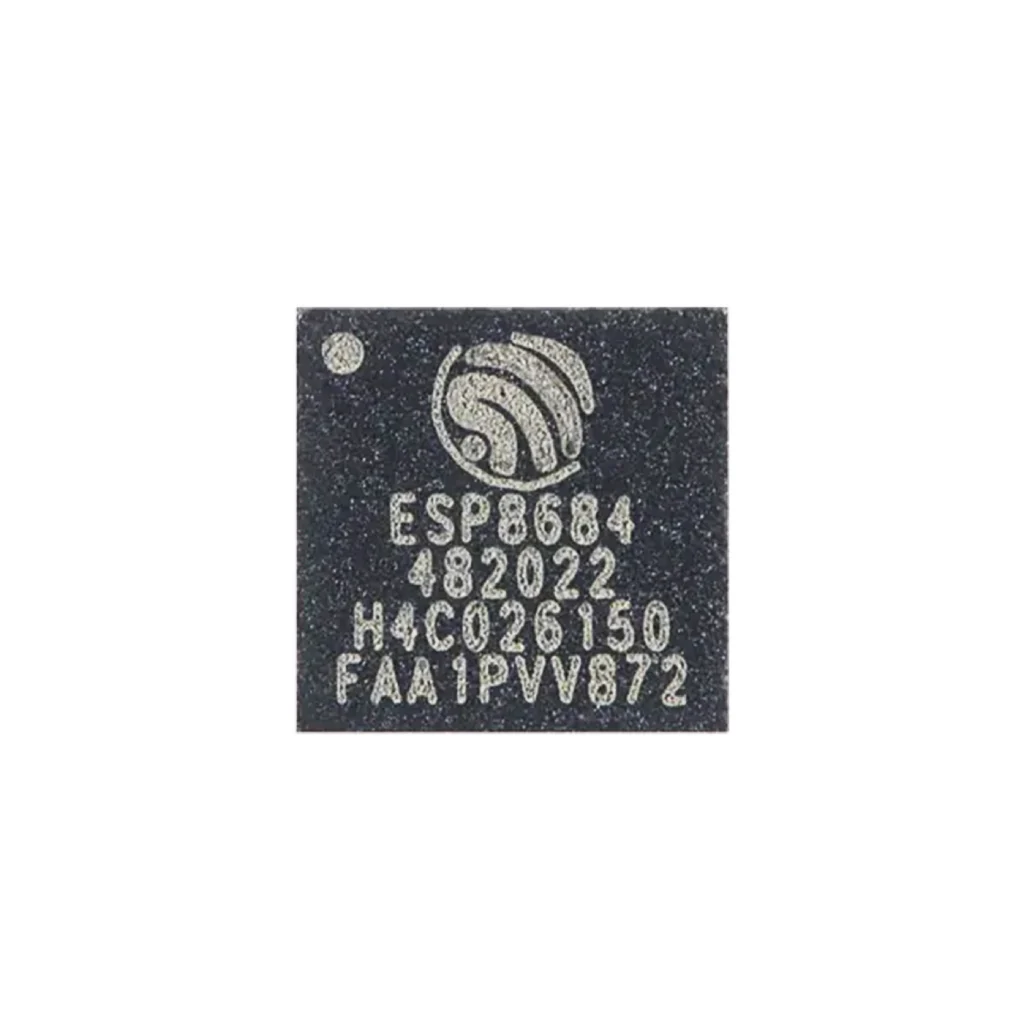
At the heart of this board is the ESP32-C2, marketed name for the ESP8684 chip: a single-core RISC-V SoC from Espressif with integrated 2.4GHz Wi-Fi, a secure bootloader and hardware encryption, built for low-cost, low-resource applications.
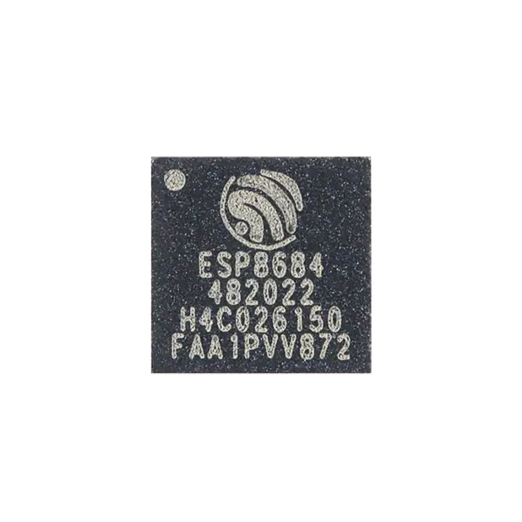
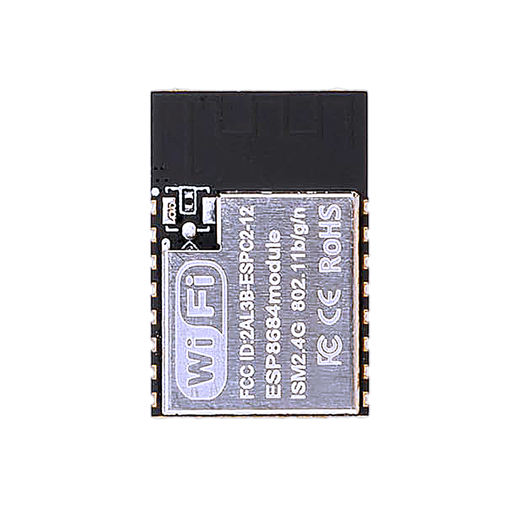
The board carries the ESP8684-WROOM-02 module: the chip, 2MB of SPI flash, a PCB antenna and the surrounding passives in one shielded package.
The development board itself breaks the module’s pins out to a breadboard-friendly, clearly labeled NodeMCU-style header, adds a CH340C USB-to-serial chip, and uses USB-C instead of micro-USB.
Key features
- Wi-Fi 802.11 b/g/n (2.4GHz)
- 12-bit ADC on 5 of the exposed pins
- UART, SPI, I²C and PWM, all software-assignable
- USB-to-serial via onboard CH340C, no separate programmer needed
- USB-C connector
- 2MB flash, embedded in the module
This is a smaller, cheaper board than the ESP32-S3/-C3/-C6 family: fine for simple sensors, wireless switches and other low-power, low-complexity connected devices, not for anything CPU- or memory-heavy.
GPIO quick reference
| GPIO | Function | ADC | PWM | Notes |
|---|---|---|---|---|
| 0 | — | No | Yes | General purpose |
| 1 | ADC1_CH0 | Yes | Yes | Analog input |
| 2 | ADC1_CH1, SPI MOSI | Yes | Yes | |
| 3 | ADC1_CH2, SPI MISO | Yes | Yes | |
| 4 | ADC1_CH3, SPI SCLK | Yes | Yes | |
| 5 | ADC1_CH4 | Yes | Yes | Analog input |
| 6 | I²C SDA | No | Yes | Default I²C pin, remappable |
| 7 | I²C SCL | No | Yes | Default I²C pin, remappable |
| 9 | BOOT strap | No | — | Hold low at reset to enter flash mode |
| 10 | SPI CS | No | Yes | |
| 20 | UART0 TX | No | Yes | To CH340C, to your PC |
| 21 | UART0 RX | No | Yes | From CH340C, from your PC |
All GPIOs are bidirectional digital I/O and support PWM. Remap I²C in Arduino with Wire.begin(SDA, SCL).
Flashing
Thanks to the onboard CH340C, flashing is plug-and-play over USB-C, no external USB-to-serial adapter needed.
- Connect the board via USB-C.
- In Arduino IDE or PlatformIO, select a generic ESP32C2 Dev Module board.
- Click Upload.
- If flashing fails to start automatically, hold IO9 (BOOT) low, tap EN/RESET, release IO9, then retry.
Do not hold IO9 low outside of flashing, it forces the board back into the bootloader instead of running your program.
Conclusion
The NodeMCU-ESP32-C2 trades GPIO count and processing power for cost and simplicity. If a project genuinely only needs Wi-Fi plus a handful of digital/analog pins, this is a cheaper, lower-power alternative to reaching for an ESP-WROOM-32D or ESP32-C3 board. For anything needing more GPIOs, Bluetooth, or more RAM, look at this site’s other ESP32 boards instead.
Related
 Reference
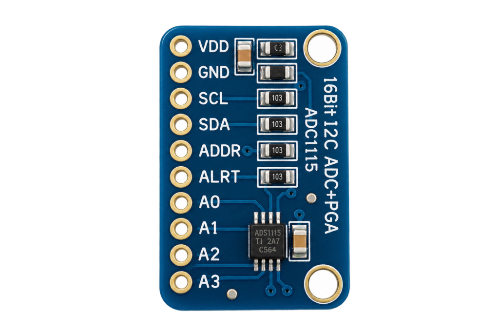
ADS1115 16-Bit ADC
A precision 16-bit I2C analog-to-digital converter for when the ESP32’s own noisy 12-bit ADC is not accurate enough. Covers single-ended and differential inputs, the programmable gain amplifier, and reading a signed conversion result correctly.
Read more
Reference
ADS1115 16-Bit ADC
A precision 16-bit I2C analog-to-digital converter for when the ESP32’s own noisy 12-bit ADC is not accurate enough. Covers single-ended and differential inputs, the programmable gain amplifier, and reading a signed conversion result correctly.
Read more
 Reference
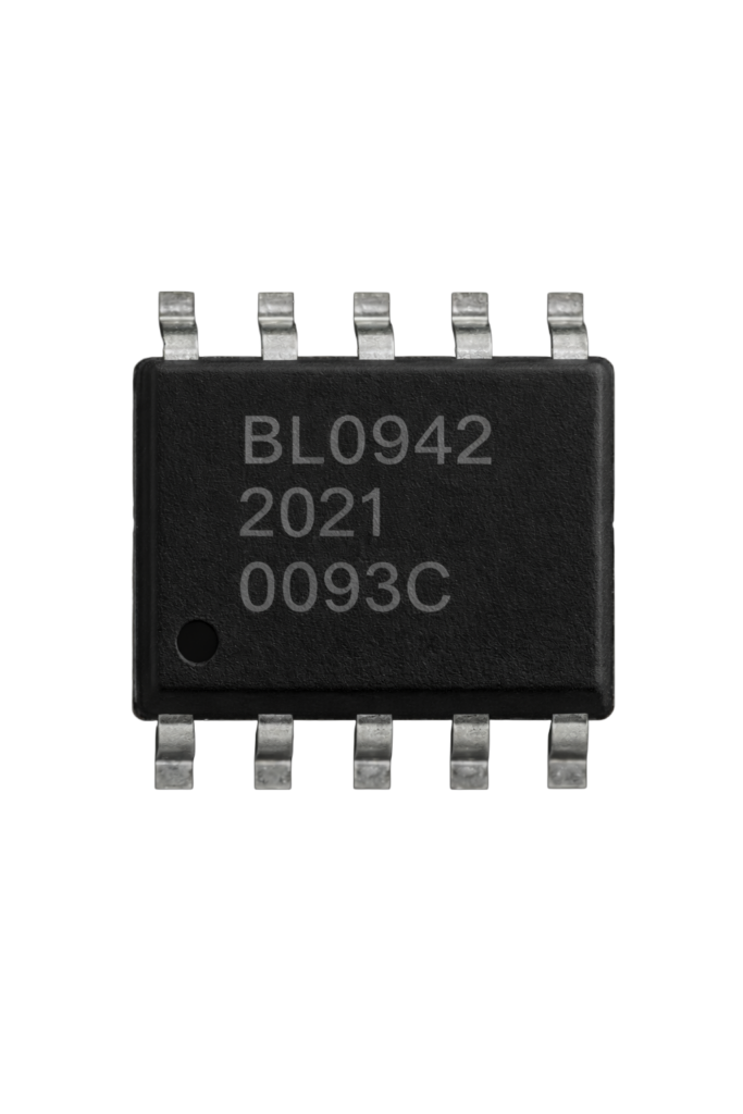
The Ultimate Guide to the BL0942 Energy Meter IC
A calibration-free, register-driven single-phase energy metering IC: active power, RMS, line frequency and zero-crossing, all exposed over UART or SPI instead of pulse-counting alone. This guide covers its pinout, digital interfaces, and how it compares to the older BL0937.
Read more
Reference
The Ultimate Guide to the BL0942 Energy Meter IC
A calibration-free, register-driven single-phase energy metering IC: active power, RMS, line frequency and zero-crossing, all exposed over UART or SPI instead of pulse-counting alone. This guide covers its pinout, digital interfaces, and how it compares to the older BL0937.
Read more
 Guide
ESP32-C2 (ESPC2-02) Pinout
The complete pin reference for the ESPC2-02 module: Espressif’s smallest, lowest-cost Wi-Fi and Bluetooth chip, and the exact pins you can safely reuse.
Read more
Guide
ESP32-C2 (ESPC2-02) Pinout
The complete pin reference for the ESPC2-02 module: Espressif’s smallest, lowest-cost Wi-Fi and Bluetooth chip, and the exact pins you can safely reuse.
Read more
More guides
Keep building.
From ESP32 HomeKit accessories to Arduino and ATtiny reference guides, there’s more where this came from.
All guides