
Reference
PN532 NFC Module Complete Guide
The PN532 reads and writes NFC tags, including the kind your phone already uses for tap-to-pay and tap-to-share, not just the 13.56MHz RFID cards the already-published RC522 handles. This guide covers its three interfaces, wiring it to an ESP32 over I2C, and when you actually need NFC over plain RFID.
- 13.56 MHz NFC
- I2C
- SPI or UART
- Up to about 50 mm
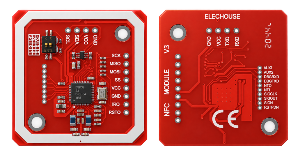
The PN532 is an NFC (Near Field Communication) controller IC from NXP, sold on breakout boards (commonly the Elechouse PN532 NFC/RFID module V3/V4) that support three different host interfaces on the same board: I2C, SPI, and UART (HSU). It reads and writes NFC tags at 13.56MHz, including NDEF-formatted tags, and can also read a phone’s NFC in card-emulation or peer-to-peer mode.
The chip numbers in this guide come from the NXP PN532 datasheet. Breakout board details come from common practice, so check your own board.
PN532 vs. RC522: which do you need?
Both chips operate at 13.56MHz and can read common MIFARE cards, but they aren’t the same thing:
| PN532 | RC522 | |
|---|---|---|
| Protocol | Full NFC Forum stack (NDEF, card emulation, peer-to-peer) | 13.56MHz RFID (MIFARE) only |
| Reads phone NFC (tap-to-share) | Yes | No |
| Interfaces | I2C, SPI, UART, selectable on one board | SPI on most boards (the chip also supports I2C and UART) |
| Cost | Higher | Lower, more common in beginner kits |
Pick the RC522 for simple access-control/attendance projects reading plain MIFARE cards, it’s cheaper and simpler. Pick the PN532 if you need to read/write phone NFC, NDEF tags (like the kind used for “tap to open a URL”), or need a peer-to-peer NFC link.
Interfaces and Pinout
Most PN532 breakout boards have a physical switch to select the interface. The pins used for I2C and UART (HSU) modes are shared and printed on the front of the board, SPI mode uses separate pins printed on the back.
| Mode | Pins used |
|---|---|
| I2C | VCC, GND, SDA, SCL |
| SPI | VCC, GND, SCK, MISO, MOSI, SS, (RSTPDN optional) |
| UART (HSU) | VCC, GND, TXD, RXD |
Default I2C address is 0x24 (7-bit). Supply voltage is 3.3V–5.5V depending on the board, most breakouts include their own regulator.
Dimensions
The PN532 chip is a 40-pin HVQFN package (plastic, very thin, no leads). You always buy it on a breakout board with an antenna: the Elechouse V3 board is a red board with a printed antenna coil of about the size of a credit card corner, and sizes vary between makers, so measure yours before you design a case. The reading range depends on the antenna, so keep metal and other electronics away from it.
Source: NXP PN532 datasheet for the package. Board sizes are not given.
Wiring to an ESP32 (I2C mode)
| PN532 Pin | ESP32 Pin |
|---|---|
| VCC | 3.3V |
| GND | GND |
| SDA | GPIO21 |
| SCL | GPIO22 |
Arduino code (Adafruit PN532 library)
#include <Wire.h>
#include <Adafruit_PN532.h>

Adafruit_PN532 nfc(-1, -1); // I2C mode, no IRQ/reset pins wired

void setup() {
  Serial.begin(115200);
  Wire.begin(21, 22);
  nfc.begin();
  if (!nfc.getFirmwareVersion()) {
    Serial.println("Didn't find PN532 board");
    while (1) delay(10);
  }
  nfc.SAMConfig();
}

void loop() {
  uint8_t uid[7];
  uint8_t uidLength;
  if (nfc.readPassiveTargetID(PN532_MIFARE_ISO14443A, uid, &uidLength)) {
    Serial.print("Found card, UID: ");
    for (uint8_t i = 0; i < uidLength; i++) {
      Serial.print(uid[i], HEX);
      Serial.print(" ");
    }
    Serial.println();
  }
  delay(500);
}
Install “Adafruit PN532” via the Arduino Library Manager, or the elechouse/PN532 library which also supports SPI and UART modes with the same board.
Practical Applications
- Phone-tap automation: trigger a smart-home scene when a phone with NFC enabled taps the reader.
- Writable NDEF tags: program a physical tag to open a URL or trigger an action on tap.
- Access control: read MIFARE card/keyfob UIDs, same use case the RC522 covers.
- Device-to-device pairing: peer-to-peer NFC mode for two NFC-capable devices to exchange data.
Real gotchas
- The interface is chosen with switches. The two switches (or solder pads) on the board select HSU (UART), I2C or SPI. A wrong setting gives “Didn’t find PN532”. Power off before you change them.
- The I2C address is 0x24. The datasheet gives it as 0x48 in its 8-bit write form, and the 7-bit address that Arduino code uses is 0x24.
- Supply range. The chip takes 2.7 to 5.4 V, and the host interface voltage (PVDD) is 1.6 to 3.6 V. Most boards have a regulator and level shifting, but check that your board accepts the voltage you use.
- The read range is short. The datasheet states up to about 50 mm in reader/writer mode, depending on the antenna. In practice it is a few centimetres with a phone or a tag.
- MIFARE Classic is supported, but it is old. The chip supports MIFARE Classic encryption in reader/writer mode, which is not secure by modern standards. Do not use a UID or a Classic card alone for security.
- Card emulation needs care. The chip supports card interface mode, but the support in libraries and in phones differs. Test with your phone.
- It needs a wake-up. From power-down the chip wakes on a command on the I2C, HSU or SPI interface, and the first command may need a short delay or be repeated.
- The SAM configuration is required. Without calling SAMConfig the reader does not scan for tags.
- Clone boards. Some boards have another antenna or a missing capacitor, which cuts the range a lot.
Safety notes
Before you wire anything up
- Keep the supply within the range of your board. The chip is rated 2.7 to 5.4 V.
- Do not rely on NFC or a UID alone for the security of a door lock or a payment.
- The reader is not a safety device. Do not use it as the only control for something dangerous.
- Never connect the board to mains voltage. Keep it on a low-voltage supply.
- Disconnect the power before you change the wiring.
Conclusion
The PN532 covers everything the RC522 does and adds real NFC support for phones and NDEF tags, at a higher price and with a slightly more involved setup across its three switchable interfaces. Either pairs cleanly with an ESP32 over I2C.
Related
 Reference
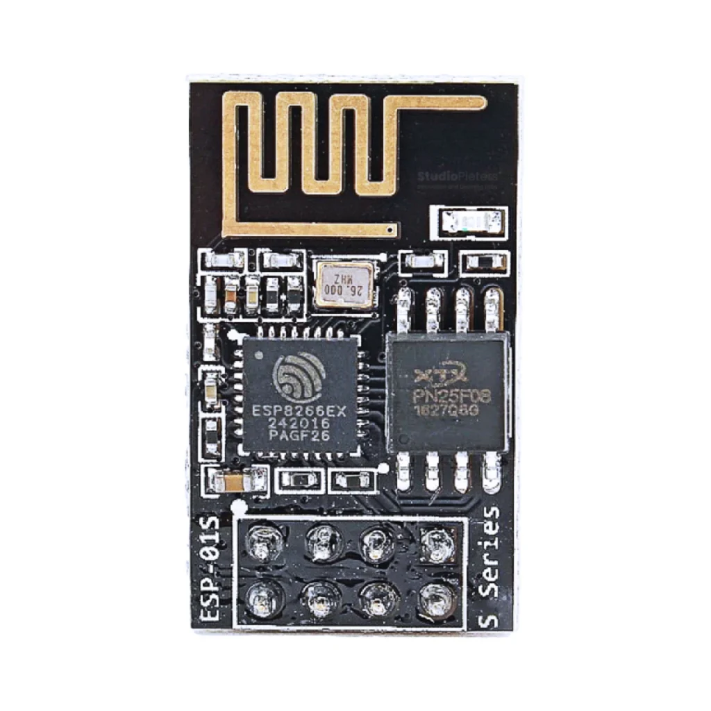
ESP8266-01 Pinout
The complete pin reference for the ESP8266-01 (ESP-01S): eight pins, two free GPIOs, boot modes, power and how to flash it.
Read more
 Guide
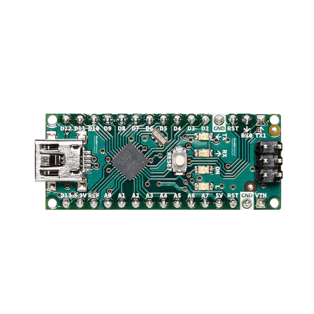
Arduino Nano Pinout
The complete pin reference for the classic ATmega328P-based Arduino Nano: 14 digital pins, 8 analog inputs, and the exact pins you can safely reuse.
Read more
 Guide
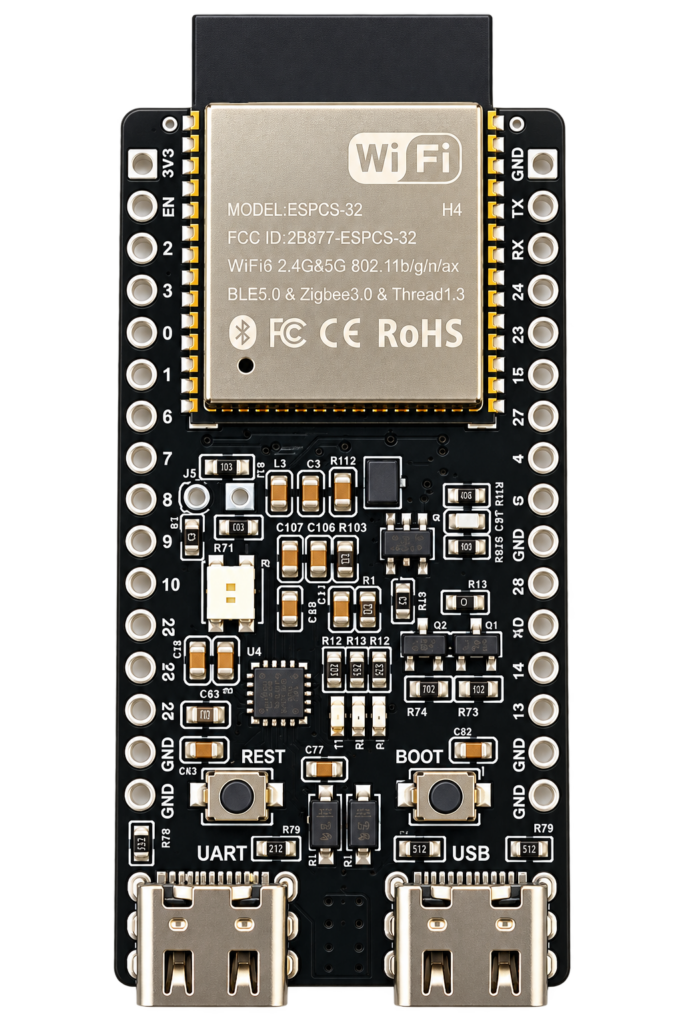
ESP32-C5 Pinout
The complete pin reference for the ESP32-C5: the first RISC-V Espressif chip with dual-band Wi-Fi 6, plus the exact pins you can safely reuse.
Read more
More guides
Keep building.
From ESP32 HomeKit accessories to Arduino and ATtiny reference guides, there’s more where this came from.
All guides