
Reference
AI-S3 Pinout
The complete pin reference for the AI-S3: an ESP32-S3-WROOM-1 board with two USB-C ports, an RGB LED, 16 MB flash, 8 MB PSRAM and 36 GPIOs.
- Dual-core Xtensa LX7
- Wi-Fi + Bluetooth LE
- 36 GPIOs
- Two USB-C
Overview
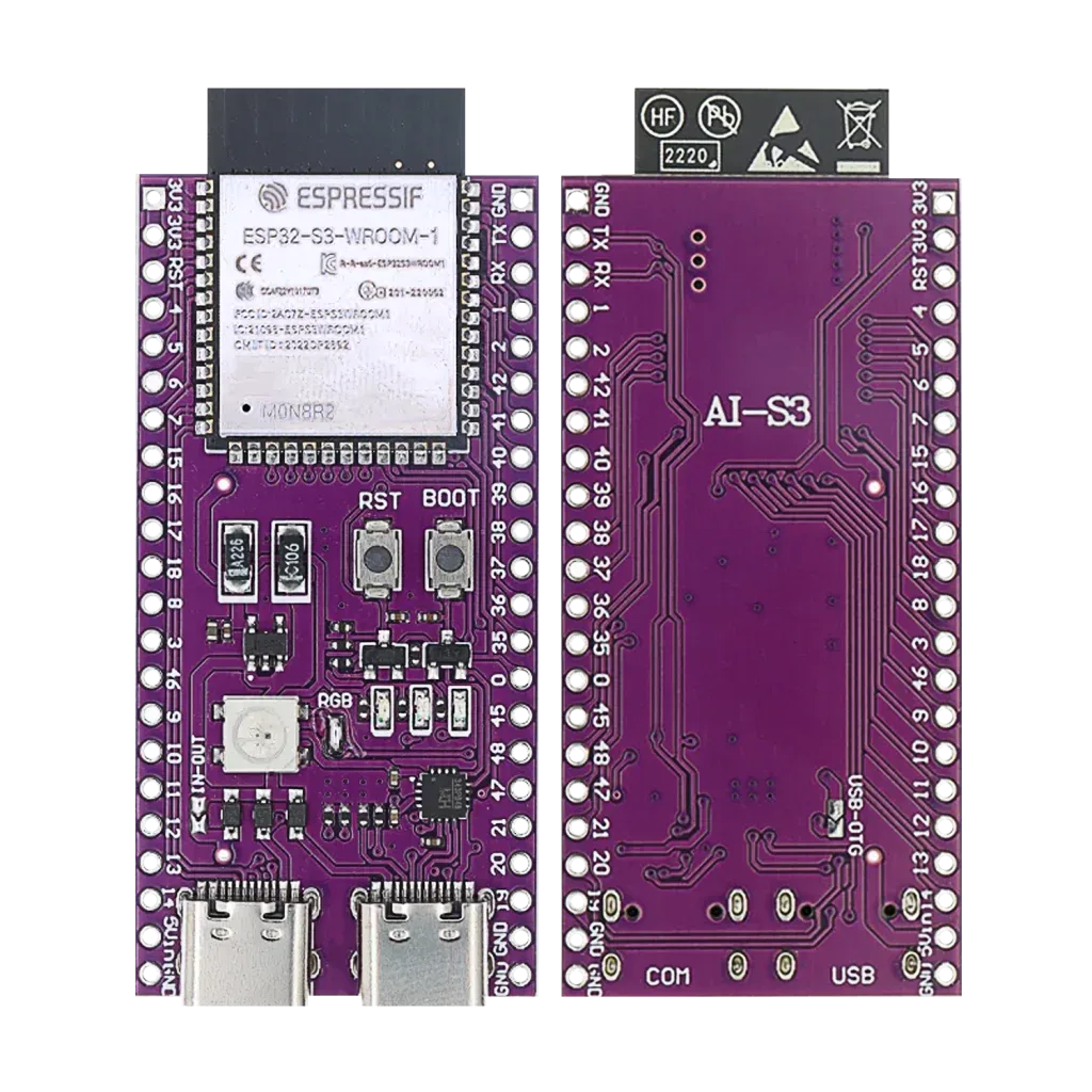
The AI-S3 is an ESP32-S3 development board on a purple PCB with two USB-C ports, an addressable RGB LED, BOOT and RST buttons and a full breakout of the ESP32-S3-WROOM-1 module: 36 GPIOs on two rows of 22 pins. The module is the N16R8 version with 16 MB of flash and 8 MB of octal PSRAM. It is the Xtensa LX7 sibling of the AI-C3, with the extra power and the AI instructions that the S3 adds.


No 802.15.4 radio on this chip, so Thread and Zigbee are not possible here: that needs an ESP32-C6 or H2 instead. Matter works over Wi-Fi. No Classic Bluetooth, only Bluetooth LE. Only badges for what this exact chip supports are shown.
System-on-chip and module
The ESP32-S3 is Espressif’s dual-core Xtensa LX7 chip (up to 240 MHz) with Wi-Fi 4 (802.11 b/g/n, 2.4 GHz only), Bluetooth 5 LE and a full-speed USB OTG interface. The board is built on the ESP32-S3-WROOM-1 module: chip, flash, PSRAM, crystal and PCB antenna in one shielded package of 18.0 x 25.5 mm.
| Part | What it does |
|---|---|
| ESP32-S3-WROOM-1 (N16R8) | Module with 16 MB flash and 8 MB octal PSRAM |
| USB-to-UART chip | Behind the COM port, connected to UART0 (GPIO43 and GPIO44) |
| USB-C, COM | Power, flashing and the serial monitor |
| USB-C, USB | Power, and the chip’s own USB OTG on GPIO19 (D-) and GPIO20 (D+) |
| WS2812 RGB LED | Addressable LED on GPIO48, printed RGB, with IN-OUT pads on the board |
| BOOT and RST buttons | BOOT pulls GPIO0 low for download mode, RST pulls the EN pin low and resets the chip |
| Two pin rows | 22 pins per row at 2.54 mm pitch: 36 GPIOs, EN, two 3V3, one 5V and four GND |
Getting started
Use the COM port first. It goes through a USB-to-UART chip that works with any serial monitor. Some systems need a driver for that chip: if the board does not show up as a serial port, check the chip on your board and install its driver.
Hello World: blink an LED
The microcontroller equivalent of “Hello World”: GPIO21 toggles once a second, shown here in two environments. Wire an LED (with a resistor) to GPIO21, a plain general-purpose pin with no other job on this board.
ESP-IDF (stable v6.1)
#include "freertos/FreeRTOS.h"
#include "freertos/task.h"
#include "driver/gpio.h"

#define LED_PIN GPIO_NUM_21

void app_main(void)
{
    gpio_reset_pin(LED_PIN);
    gpio_set_direction(LED_PIN, GPIO_MODE_OUTPUT);

    while (1) {
        gpio_set_level(LED_PIN, 1);
        vTaskDelay(pdMS_TO_TICKS(1000));
        gpio_set_level(LED_PIN, 0);
        vTaskDelay(pdMS_TO_TICKS(1000));
    }
}
Arduino IDE
#define LED_PIN 21

void setup() {
  pinMode(LED_PIN, OUTPUT);
}

void loop() {
  digitalWrite(LED_PIN, HIGH);
  delay(1000);
  digitalWrite(LED_PIN, LOW);
  delay(1000);
}
ESP-IDF: build and flash with idf.py build flash monitor. Arduino IDE: install ESP32 board support first, see Getting started above.
Specifications
Specifications for the AI-S3 board and its ESP32-S3-WROOM-1 module.
Compute
| Chip | ESP32-S3 |
| CPU | Dual-core Xtensa LX7, up to 240 MHz |
| Memory | 512 KB SRAM, 384 KB ROM, 8 MB octal PSRAM |
| Flash | 16 MB |
Radio
| Wi-Fi | 802.11 b/g/n, 2.4 GHz |
| Bluetooth | 5 LE (no Classic Bluetooth) |
| USB | Full-speed USB OTG (device and host) |
| Security | Secure boot, flash encryption |
Physical
| Operating voltage | 3.3 V |
| Module size | 18.0 x 25.5 x 3.1 mm |
| Board size | about 27.1 x 56.7 mm (read from the drawing) |
| GPIOs | 36 on the header |
| ADC | Two 12-bit ADCs, 20 channels (GPIO1 to GPIO20) |
| Touch pins | 14 (GPIO1 to GPIO14) |
Dimensions
The two pin rows are 24.6 mm apart and each has 22 pins on a 2.54 mm pitch, 53.34 mm from the first to the last pin. The board itself is about 27.1 x 56.7 mm and the module overhangs the top edge of the board.

These sizes are read from the drawing of the board, using the 2.54 mm pin pitch as the scale, and not measured on a board. Check them with a caliper before you design an enclosure.
Pinout diagram
The component side with every header pin, its GPIO number and its functions: touch pad, ADC channel, JTAG, the default I2C, SPI and UART pins of the Arduino core, and the USB pins. The pin rows are the same as on the ESP32-S3-DevKitC-1.

Underside
The underside is the same board seen from the other side. The left and right rows are mirrored compared with the component side.

The default pins (SDA 8, SCL 9, SS 10, MOSI 11, SCK 12, MISO 13, TX 43, RX 44) come from the ESP32S3 Dev Module variant in the Arduino ESP32 core. The ADC, touch, JTAG, strapping and USB functions come from the ESP32-S3 data sheet.
GPIO map at a glance
The same pins grouped by what they can do. GPIO1 to GPIO14 are the most flexible: touch and analog input on one pin.

Power
The board runs from either USB-C port. The header has one 5V pin, two 3V3 pins and four GND pins.
| Pin | Use |
|---|---|
| 5V | The 5 V rail of the board. Use it as a 5 V output from USB for small things, or as a 5 V input when no USB cable is connected |
| 3V3 | The 3.3 V rail for the chip and for sensors. Do not feed it while the board is also powered from USB |
| GND | Four ground pins on the two rows |
| RST (EN) | The reset input of the chip, also wired to the RST button |
Use only one power source at a time: a USB-C port, the 5V pin or the 3V3 pins. Motors, servos and LED strips should have their own supply with a shared ground, because Wi-Fi bursts and a camera or display already load the board’s regulator.
USB-C, flashing and reset
The AI-S3 has two USB-C ports, printed COM and USB next to the connectors.
| Port | Connected to | Use it for |
|---|---|---|
| COM | A USB-to-UART chip, UART0 (GPIO43 TX, GPIO44 RX) | Power, flashing and the serial monitor. Start with this one |
| USB | The chip’s own USB OTG (GPIO19 D-, GPIO20 D+) | Power, native USB devices such as a keyboard, mouse or mass storage, a serial port (CDC) and JTAG debugging |
In the Arduino IDE Serial uses the COM port. To print over the USB port instead, set USB CDC On Boot to Enabled.
If the upload does not start: hold BOOT (GPIO0), tap RST, then release BOOT. That puts the chip in download mode on either port.
| Function | Pin | Description |
|---|---|---|
| BOOT button | GPIO0 | Hold low at reset to enter download mode |
| RST button | EN | Reset the chip |
| USB D- / D+ | GPIO19 / GPIO20 | Native USB OTG, the USB port |
| UART0 TX / RX | GPIO43 / GPIO44 | Serial, the COM port |
ADC, touch and the missing DAC
GPIO1 to GPIO14 are the most flexible pins of the board: every one of them is a touch pad, and the first ten are also on the first analog converter.
| Feature | Pins | Notes |
|---|---|---|
| ADC1 | GPIO1 to GPIO10 | Works at any time, also while Wi-Fi is on. Use these for analog sensors |
| ADC2 | GPIO11 to GPIO20 | Shares hardware with Wi-Fi: readings are unreliable while Wi-Fi is active. Fine for digital use |
| Touch | GPIO1 to GPIO14 | 14 capacitive touch pads, TOUCH1 to TOUCH14 |
| DAC | none | The ESP32-S3 has no DAC. Use PWM and a filter, or I2S for audio |
The ADC input range is small with the default attenuation. Use a voltage divider for signals above the range and never put more than 3.3 V on any pin.
Pins with a second job
- GPIO0, GPIO3, GPIO45 and GPIO46 are strapping pins that the chip reads at power-up. GPIO0 is the BOOT button. Do not hold the others high or low with an external circuit while the board starts.
- GPIO35, GPIO36 and GPIO37 are wired to the octal PSRAM of the N16R8 module. They are printed on the header, but you cannot use them.
- GPIO48 is the WS2812 RGB LED. GPIO8 and GPIO9 are the default I²C pins (SDA and SCL), GPIO10 to GPIO13 the default SPI pins (SS, MOSI, SCK, MISO).
- GPIO39 to GPIO42 are the JTAG pins (MTCK, MTDO, MTDI, MTMS). They work as normal pins, but you lose them when you debug with an external JTAG probe.
- GPIO15 and GPIO16 are the pins for an optional 32 kHz crystal (XTAL_32K_P and XTAL_32K_N). They are free if you do not add one.
- GPIO17 and GPIO18 are the default UART1 pins (TX and RX).
- GPIO19 and GPIO20 are USB D- and D+ of the USB port. Do not use them as plain GPIO if you use the native USB.
- GPIO43 and GPIO44 are UART0 TX and RX, used by the COM port and the serial monitor.
GPIO quick reference
All 36 pins of the headers that carry a GPIO, in order of number. None of them is input-only.
| GPIO | Special function | ADC | Touch | Boot state |
|---|---|---|---|---|
| 0 | BOOT button, strapping | – | – | Strapping |
| 1 | – | ADC1_CH0 | T1 | Free |
| 2 | – | ADC1_CH1 | T2 | Free |
| 3 | Strapping (JTAG source) | ADC1_CH2 | T3 | Strapping |
| 4 | – | ADC1_CH3 | T4 | Free |
| 5 | – | ADC1_CH4 | T5 | Free |
| 6 | – | ADC1_CH5 | T6 | Free |
| 7 | – | ADC1_CH6 | T7 | Free |
| 8 | I2C SDA (Arduino default) | ADC1_CH7 | T8 | Free |
| 9 | I2C SCL (Arduino default) | ADC1_CH8 | T9 | Free |
| 10 | SPI SS (Arduino default) | ADC1_CH9 | T10 | Free |
| 11 | SPI MOSI (Arduino default) | ADC2_CH0 | T11 | Free |
| 12 | SPI SCK (Arduino default) | ADC2_CH1 | T12 | Free |
| 13 | SPI MISO (Arduino default) | ADC2_CH2 | T13 | Free |
| 14 | – | ADC2_CH3 | T14 | Free |
| 15 | XTAL_32K_P | ADC2_CH4 | – | Free |
| 16 | XTAL_32K_N | ADC2_CH5 | – | Free |
| 17 | UART1 TX (Arduino default) | ADC2_CH6 | – | Free |
| 18 | UART1 RX (Arduino default) | ADC2_CH7 | – | Free |
| 19 | USB D- (USB port) | ADC2_CH8 | – | Free |
| 20 | USB D+ (USB port) | ADC2_CH9 | – | Free |
| 21 | – | – | – | Free |
| 35 | Octal PSRAM, not usable | – | – | Not usable |
| 36 | Octal PSRAM, not usable | – | – | Not usable |
| 37 | Octal PSRAM, not usable | – | – | Not usable |
| 38 | – | – | – | Free |
| 39 | JTAG MTCK | – | – | Free |
| 40 | JTAG MTDO | – | – | Free |
| 41 | JTAG MTDI | – | – | Free |
| 42 | JTAG MTMS | – | – | Free |
| 43 | UART0 TX (COM port) | – | – | Free |
| 44 | UART0 RX (COM port) | – | – | Free |
| 45 | Strapping (flash voltage) | – | – | Strapping |
| 46 | Strapping (boot mode and boot messages) | – | – | Strapping |
| 47 | – | – | – | Free |
| 48 | RGB LED (WS2812) | – | – | Free |
Flashing pins
The COM port is wired to UART0 through the USB-to-UART chip. These are the pins involved, in case you connect your own USB-to-serial adapter.
| Function | Pin | Description |
|---|---|---|
| TXD0 | GPIO43 | AI-S3 to PC (output) |
| RXD0 | GPIO44 | PC to AI-S3 (input) |
| BOOT | GPIO0 | Hold low at reset to enter download mode |
| EN | RST button | Resets the chip |
Programming
Arduino IDE, PlatformIO and ESP-IDF all work. In the Arduino IDE choose ESP32S3 Dev Module.
| Setting | Value for the N16R8 module |
|---|---|
| Flash size | 16MB (128Mb) |
| PSRAM | OPI PSRAM |
| Partition scheme | One that fits 16 MB, for example 16M Flash (3MB APP/9.9MB FATFS) |
| USB CDC On Boot | Enabled only if you want Serial on the USB port |
| Upload | Through the COM port, or the USB port in download mode |
PSRAM is not automatic: switch it on in the build settings and choose OPI, the type of this module. The wrong choice means no PSRAM or a boot loop.
Colour cycle on the RGB LED
void setup() {}

void loop() {
  rgbLedWrite(48, 32, 0, 0);   // red
  delay(500);
  rgbLedWrite(48, 0, 32, 0);   // green
  delay(500);
  rgbLedWrite(48, 0, 0, 32);   // blue
  delay(500);
}
I²C scan on the default pins
#include <Wire.h>

void setup() {
  Serial.begin(115200);
  Wire.begin();            // SDA = GPIO8, SCL = GPIO9
  delay(2000);
  for (uint8_t a = 1; a < 127; a++) {
    Wire.beginTransmission(a);
    if (Wire.endTransmission() == 0) Serial.printf("Found 0x%02Xn", a);
  }
}

void loop() {}
I did not run these two sketches on a board, they follow the Arduino ESP32 API. Start with the LED: it needs no extra parts.
Tips
- Use ADC1 for sensors. GPIO1 to GPIO10 keep working with Wi-Fi on.
- Start on the COM port. It works with any serial monitor without extra settings.
- Use the touch pads. A wire or a copper pad on GPIO1 to GPIO14 gives you a button without any extra part.
- Keep the strapping pins quiet. GPIO0, GPIO3, GPIO45 and GPIO46 should not be pulled hard by external circuits at power-up.
- Use the PSRAM for big buffers. Camera frames, audio and AI models fit in the 8 MB.
- Check the fit before you use a breadboard. The pin rows are 24.6 mm apart and the board is wide, which leaves few free holes next to the pins. Header sockets or jumper wires are easier.
Real gotchas
- GPIO35, 36 and 37 are not usable. They are printed on the header, but wired to the octal PSRAM of the N16R8 module.
- USB D+ and D- are easy to swap. GPIO19 is D- and GPIO20 is D+.
- ADC2 and Wi-Fi. ADC2 (GPIO11 to GPIO20) shares resources with the Wi-Fi radio, so readings are unreliable while Wi-Fi is on.
- PSRAM must be enabled. Choose OPI PSRAM in the build settings, not QSPI.
- Two ports, two serial ports. The serial monitor must point at the port you are using. Without USB CDC On Boot,
Serialprints on the COM port only. - Which pin is the RGB LED? On this board it is GPIO48. Other ESP32-S3 boards use another pin, so do not copy the pin from a different board.
- 2.4 GHz only. No 5 GHz Wi-Fi and no Classic Bluetooth.
- 3.3 V logic. The pins are not 5 V tolerant. The 5V pin is a power pin, not a signal pin.
- Limited current. Power motors, servos and strips from their own supply.
Compared with other boards
Common versions of these chips, with the facts that matter when you choose.
| ESP32-S3 (AI-S3) | ESP32-C3 (AI-C3) | ESP32-S2 | ESP32 (classic) | |
|---|---|---|---|---|
| CPU | 2 x Xtensa LX7, 240 MHz | 1 x RISC-V, 160 MHz | 1 x Xtensa LX7 | 2 x Xtensa LX6 |
| Wireless | Wi-Fi 4 and Bluetooth 5 LE | Wi-Fi 4 and Bluetooth 5 LE | Wi-Fi 4 | Wi-Fi 4 and Bluetooth |
| Native USB | OTG | USB Serial/JTAG | OTG | No |
| Touch pads | 14 | None | 14 | 10 |
| DAC | None | None | 2 (8-bit) | 2 (8-bit) |
| AI instructions | Yes (vector) | No | No | No |
Take the AI-S3 when you need more power, PSRAM, native USB OTG or small AI models. For a cheaper RISC-V board see the AI-C3, for the same board family with touch and native USB but no Bluetooth see the ESP32-S2 Mini. Need something smaller instead? See the ESP32-S3 Zero.
What to build with it
- A voice assistant or wake-word detector with an I2S microphone and speaker.
- Face or object detection with ESP-WHO or ESP-DL, with a camera on the free pins.
- A USB keyboard, mouse or macro pad through the USB port.
- A HomeKit or Matter accessory over Wi-Fi.
- A touch-controlled panel using the 14 touch pads, with the RGB LED as feedback.
Safety notes
Before you wire anything up
- GPIO0, GPIO3, GPIO45 and GPIO46 are strapping pins, check their boot-time state before using them as outputs.
- GPIO19 and GPIO20 are the native USB pins, avoid reassigning them if you use the USB port.
- This board runs at 3.3 V logic, a 5 V signal on any pin can damage the chip.
- Use only one power source at a time: a USB-C port, the 5V pin or the 3V3 pins.
Conclusion
The AI-S3 gives you the ESP32-S3’s extra compute, native USB OTG, touch pads and AI instructions on a compact board with two USB-C ports, 16 MB of flash and 8 MB of PSRAM. Keep sensors on ADC1, stay away from GPIO35 to GPIO37, switch on OPI PSRAM and use the COM port for your first upload. For the family overview see the ESP32 family explained.
Sources: the pin layout and names from the drawing of the AI-S3, the ESP32-S3 and ESP32-S3-WROOM-1 data sheets, the ESP32S3 Dev Module variant in the Arduino ESP32 core and the ESP-IDF documentation. The board size and the roles of the two USB ports are read from the drawing and the silkscreen, the module variant (N16R8) is as given by the owner of the board.
Related
 Guide
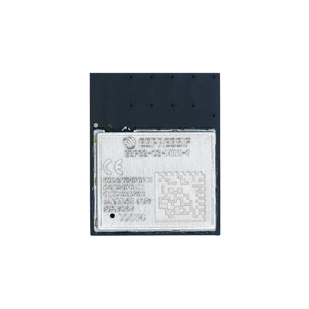
ESP32-C3-MINI-1 Pinout
The complete pin reference for the ESP32-C3-MINI-1 module: a single RISC-V core, Wi-Fi and Bluetooth LE, and the exact pins you can safely reuse.
Read more
 Reference
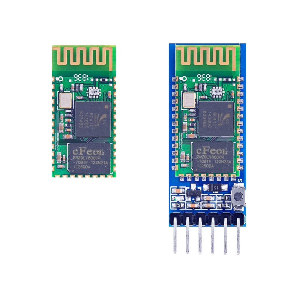
HC-05 Bluetooth Module Pinout
The HC-05 is a Bluetooth to serial module: it replaces a serial cable with a wireless link. The pinout of the 6-pin breakout board and of the bare 34-pad module on both sides, how to enter AT mode, the real default settings from the datasheet and the AT command set, and the 3.3 V limits to know before you wire it to a 5 V board.
Read more
 Reference
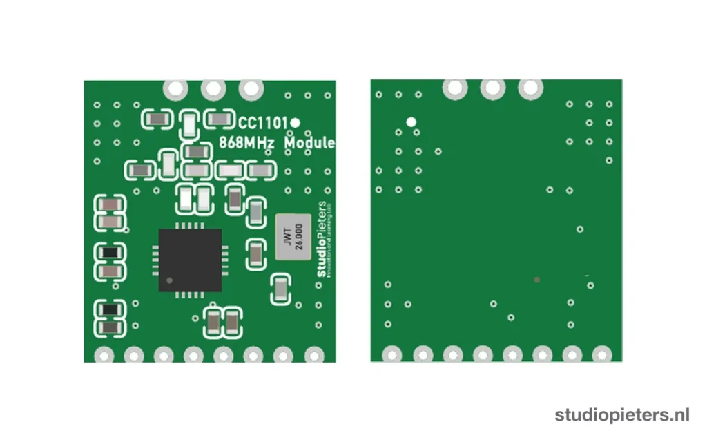
CC1101 868MHz SPI RF Module – Complete Guide
A programmable sub-GHz transceiver for the 868 MHz ISM band with hardware packet handling, CRC and RSSI built in. The pinout of the module with labeled diagrams, ESP32 wiring, ESP-IDF SPI setup, register configuration, and how it compares to LoRa.
Read more
More guides
Keep building.
From ESP32 HomeKit accessories to Arduino and ATtiny reference guides, there’s more where this came from.
All guides