
Reference
ESP32-S2 Mini Pinout
The complete pin reference for the WEMOS/Lolin S2 Mini: native USB, 14 capacitive touch pins, and no Bluetooth at all.
- Single-core Xtensa LX7
- Wi-Fi only
- no Bluetooth
- 27 GPIOs on the headers
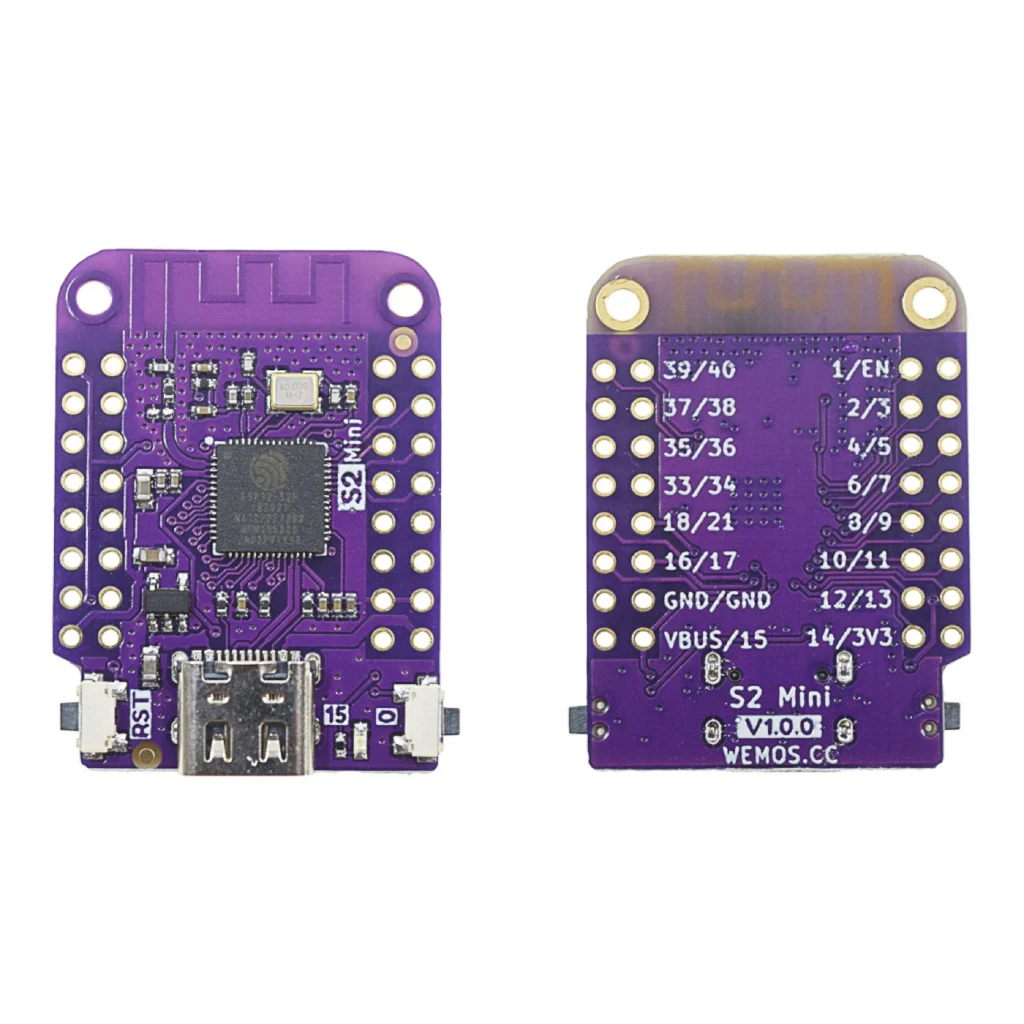
Overview
The S2 Mini is a compact ESP32-S2 development board made by WEMOS/Lolin, with onboard USB-C, a reset button, a 3.3 V regulator and 27 GPIOs on the headers (two rows of pins on each long side). The ESP32-S2 is Espressif’s Wi-Fi-only chip, no Bluetooth, no 802.15.4, which makes it a good fit for USB-powered sensors and gadgets that do not need a second radio.

No Bluetooth badge here on purpose: unlike every other chip in these guides, the ESP32-S2 genuinely has no Bluetooth radio at all, not even BLE.
System-on-chip and board
The ESP32-S2 is Espressif’s single-core Xtensa LX7 chip (up to 240 MHz) with Wi-Fi 4 (802.11 b/g/n, 2.4 GHz only) and a full-speed native USB interface. It has no Bluetooth at all, not even BLE, and no second core. What it adds compared with the classic ESP32 is the native USB (so no USB-to-serial chip is needed), 14 capacitive touch pads and a small RISC-V coprocessor that can run while the main core sleeps.
The S2 Mini uses the ESP32-S2FN4R2: the “F” means the flash is inside the chip package, “N4” is 4 MB of flash and “R2” is 2 MB of PSRAM.
| Part | What it does |
|---|---|
| ESP32-S2FN4R2 | Main processor with 4 MB flash and 2 MB PSRAM in one package |
| ME6211C33 | 3.3 V regulator that makes the supply for the chip from the 5 V on the USB-C port or the VBUS pin |
| USB-C connector | Power, flashing and the serial monitor, wired to the chip’s native USB (GPIO19 and GPIO20) |
| Button 0 | Pulls GPIO0 low: BOOT button for the bootloader. GPIO0 itself is not on the headers |
| Button RST | Pulls the EN pin low and resets the board |
| Blue LED | On GPIO15, switched on with a high level |
| PCB antenna | Wi-Fi antenna in the copper at the top of the board |
| Two pin rows per side | 32 pins at 2.54 mm pitch: 27 GPIOs, two GND, 3V3, VBUS and EN |
Getting started
The S2 Mini uses the chip’s native USB peripheral directly, not a separate USB-to-serial chip, so no extra USB driver is usually needed on modern operating systems.
Hello World: blink an LED
The microcontroller equivalent of “Hello World”: GPIO21 toggles once a second, shown here in two environments. Wire an LED (with a resistor) to GPIO21, a plain general-purpose pin with no other job on this board.
ESP-IDF (stable v6.1)
#include "freertos/FreeRTOS.h"
#include "freertos/task.h"
#include "driver/gpio.h"

#define LED_PIN GPIO_NUM_21

void app_main(void)
{
    gpio_reset_pin(LED_PIN);
    gpio_set_direction(LED_PIN, GPIO_MODE_OUTPUT);

    while (1) {
        gpio_set_level(LED_PIN, 1);
        vTaskDelay(pdMS_TO_TICKS(1000));
        gpio_set_level(LED_PIN, 0);
        vTaskDelay(pdMS_TO_TICKS(1000));
    }
}
Arduino IDE
#define LED_PIN 21

void setup() {
  pinMode(LED_PIN, OUTPUT);
}

void loop() {
  digitalWrite(LED_PIN, HIGH);
  delay(1000);
  digitalWrite(LED_PIN, LOW);
  delay(1000);
}
ESP-IDF: build and flash with idf.py build flash monitor. Arduino IDE: install ESP32 board support first, see Getting started above.
Specifications
Specifications for the ESP32-S2 chip and the S2 Mini board.
Compute
| Chip | ESP32-S2FN4R2 |
| CPU | Single-core Xtensa LX7, up to 240 MHz |
| Flash | 4 MB |
| PSRAM | 2 MB |
Radio
| Wi-Fi | 802.11 b/g/n, 2.4 GHz |
| Bluetooth | None |
| USB | Native USB 1.1 (device and host) |
Physical
| Operating voltage | 3.3 V |
| Size | 25.4 x 34.3 mm |
| GPIOs | 43 on the chip, 27 on the headers (GPIO0 only as the BOOT button) |
| Touch pins | 14 |
| ADC | 2 x 12-bit, up to 20 channels |
Dimensions
The board is 25.4 x 34.3 mm. The pins are on a 2.54 mm pitch, 22.86 mm between the two outer rows, so the outer rows fit a D1 mini footprint.

Source: the LOLIN S2 Mini page for the board size. Pin positions are read from the drawing of the board.
Pinout diagram
The component side with every header pin: GPIO number, touch pad, ADC channel, DAC, JTAG and the default I2C, SPI and UART pins of the Arduino core for this board. The two rows on each side are the outer and the inner pin of the same line, the outer rows are pin compatible with a D1 mini.

Underside and the printed pin pairs
The silkscreen on the underside prints two numbers per row. This is how to read them.

The default pins (SDA 33, SCL 35, SS 12, MOSI 11, MISO 9, SCK 7, TX 39, RX 37, LED 15) come from the LOLIN S2 Mini variant in the Arduino ESP32 core. The ADC, touch, DAC and JTAG functions come from the ESP32-S2 data sheet.
GPIO map at a glance
The same pins grouped by what they can do. GPIO1 to GPIO14 are the most flexible: touch and analog input on one pin.

Power
The board is meant to run from its USB-C port. The ME6211C33 turns the 5 V from USB into the 3.3 V the chip needs.
| Pin | Use |
|---|---|
| VBUS | The 5 V line from the USB-C port. Use it as a 5 V output to power small things from USB, or as the 5 V input when the USB port is not connected |
| 3V3 | The 3.3 V output of the regulator, or a direct 3.3 V input to the chip. Do not feed it while the board is also powered from USB |
| GND | Two ground pins, one in each row |
| EN | The reset input. Pull it low to reset, it is also wired to the RST button |
The ME6211 is a small regulator. One source lists it at 500 mA, which has to cover the chip, the Wi-Fi bursts and everything you attach to the 3V3 pin. Servos, LED strips and motors should have their own supply with a shared ground. Use only one power source at a time: the USB-C port, the VBUS pin or the 3V3 pin.
The same source gives rough consumption figures (about 310 mA peak with Wi-Fi, 12 to 19 mA in modem sleep and 20 to 190 µA in deep sleep), but marks them as not tested, so treat them as an indication and measure your own build.
USB-C, flashing and reset
The USB-C port is connected straight to the chip’s native USB (GPIO19 is D-, GPIO20 is D+). There is no USB-to-UART chip on the board, so the same cable gives you power, flashing and the serial monitor.
| Function | Pin | Description |
|---|---|---|
| BOOT button (0) | GPIO0 | Hold low at reset to enter the bootloader |
| RST button | EN | Reset the board |
| USB D- / D+ | GPIO19 / GPIO20 | Native USB. Not on the headers |
In the Arduino IDE set USB CDC On Boot to Enabled, otherwise Serial.print does not show up in the serial monitor. In PlatformIO the equivalent build flag is -DARDUINO_USB_CDC_ON_BOOT=1.
If the upload does not start: hold the 0 button, press and release RST, then release 0. After the upload, press RST once (without 0) to start your sketch. Because the chip enumerates as a different USB device in bootloader mode, the port name can change between the bootloader and your running program.
ADC, DAC and touch
GPIO1 to GPIO14 are the most flexible pins of the board: every one of them is a touch pad, and the first ten are also analog inputs.
| Feature | Pins | Notes |
|---|---|---|
| ADC1 | GPIO1 to GPIO10 | Works at any time, also while Wi-Fi is on. Use these for analog sensors |
| ADC2 | GPIO11 to GPIO18 (on the headers) | Shares hardware with Wi-Fi: readings can fail while Wi-Fi is active. Fine for digital use |
| DAC | GPIO17 (DAC1), GPIO18 (DAC2) | Two real analog outputs, 8-bit |
| Touch | GPIO1 to GPIO14 | 14 capacitive touch pads, TOUCH1 to TOUCH14 |
With the default attenuation the ADC input range is small. At the highest attenuation (12 dB) the usable input is about 2.5 V, so do not expect to measure the full 3.3 V directly: use a voltage divider for higher signals and never feed more than 3.3 V to any pin.
Pins with a second job
- GPIO0 is a strapping pin and wired to the BOOT button. It is not on the headers. ESP-IDF lists GPIO0, GPIO45 and GPIO46 as the strapping pins of the ESP32-S2, and only GPIO0 matters here because the other two are not broken out.
- GPIO15 and GPIO16 are also the pins for an optional 32.768 kHz crystal (XTAL_32K_P and XTAL_32K_N). The board has no crystal, so you can use them as normal pins, but the blue LED sits on GPIO15.
- GPIO39 and GPIO40 are the JTAG pins MTCK and MTDO. They work as normal pins, but if you want to debug with JTAG you lose them. GPIO39 and GPIO37 are also the default TX and RX of the Arduino core for this board.
- GPIO33 and GPIO35 are the default I²C pins (SDA and SCL). Any GPIO can do I²C in software, but these two use the hardware pins of the chip.
- GPIO7, 9, 11 and 12 are the default hardware SPI pins (SCK, MISO, MOSI and SS). The pair 13/12 is printed reversed on purpose: it keeps GPIO11 and GPIO12 on the outer rows, which follow the D1 mini footprint.
GPIO quick reference
GPIO19 and GPIO20 are the chip’s native USB D+ and D- pins and are not broken out on this board, so they are not listed below.
| GPIO | Special function | ADC | DAC | Touch | Boot state |
|---|---|---|---|---|---|
| 0 | Strapping (BOOT) | – | No | Yes | Strapping |
| 1 | Touch1 | ADC1_0 | No | Yes | Free |
| 2 | Touch2 | ADC1_1 | No | Yes | Free |
| 3 | Touch3 | ADC1_2 | No | Yes | Free |
| 4 | Touch4 | ADC1_3 | No | Yes | Free |
| 5 | Touch5 | ADC1_4 | No | Yes | Free |
| 6 | Touch6 | ADC1_5 | No | Yes | Free |
| 7 | Touch7, SPI SCK (Arduino default) | ADC1_6 | No | Yes | Free |
| 8 | Touch8 | ADC1_7 | No | Yes | Free |
| 9 | Touch9, SPI MISO (Arduino default) | ADC1_8 | No | Yes | Free |
| 10 | Touch10 | ADC1_9 | No | Yes | Free |
| 11 | Touch11, SPI MOSI (Arduino default) | ADC2_0 | No | Yes | Free |
| 12 | Touch12, SPI SS (Arduino default) | ADC2_1 | No | Yes | Free |
| 13 | Touch13 | ADC2_2 | No | Yes | Free |
| 14 | Touch14 | ADC2_3 | No | Yes | Free |
| 15 | Onboard LED, XTAL_32K_P | ADC2_4 | No | No | Free |
| 16 | XTAL_32K_N | ADC2_5 | No | No | Free |
| 17 | DAC1 | ADC2_6 | Yes (DAC1) | No | Free |
| 18 | DAC2 | ADC2_7 | Yes (DAC2) | No | Free |
| 21 | – | – | No | No | Free |
| 33 | I2C SDA (Arduino default) | – | No | No | Free |
| 34 | FSPI CS0 (IO_MUX) | – | No | No | Free |
| 35 | I2C SCL (Arduino default), FSPI MOSI (IO_MUX) | – | No | No | Free |
| 36 | FSPI CLK (IO_MUX) | – | No | No | Free |
| 37 | UART RX (Arduino default), FSPI MISO (IO_MUX) | – | No | No | Free |
| 38 | – | – | No | No | Free |
| 39 | UART TX (Arduino default), JTAG MTCK | – | No | No | Free |
| 40 | JTAG MTDO | – | No | No | Free |
Flashing pins
The S2 Mini flashes over its native USB port, not a separate UART bridge, so there is no TXD0/RXD0 pin pair to route externally.
| Function | Pin | Description |
|---|---|---|
| EN | EN pin | Resets the board |
| IO0 | GPIO0 | Hold low to enter the bootloader |
Programming
Arduino IDE, PlatformIO and ESP-IDF all work. In the Arduino IDE install ESP32 board support (Espressif Systems), choose LOLIN S2 Mini, and set USB CDC On Boot to Enabled. If you use the 2 MB of PSRAM, enable PSRAM in the board options, otherwise it is not available to your program. In PlatformIO or ESPHome a generic ESP32-S2 board profile such as esp32-s2-saola-1 is used.
I²C scan on the default pins
#include <Wire.h>

void setup() {
  Serial.begin(115200);
  Wire.begin();            // SDA = GPIO33, SCL = GPIO35 on this board
  delay(2000);
  for (uint8_t a = 1; a < 127; a++) {
    Wire.beginTransmission(a);
    if (Wire.endTransmission() == 0) Serial.printf("Found 0x%02Xn", a);
  }
}

void loop() {}
Read a touch pad and an analog input
void setup() {
  Serial.begin(115200);
  analogSetPinAttenuation(1, ADC_11db);   // GPIO1 is on ADC1
}

void loop() {
  Serial.printf("touch=%u adc=%dn", touchRead(2), analogRead(1));
  delay(200);
}
I did not run these two sketches on a board, they follow the Arduino ESP32 API. Start with the I²C scan: attach any I²C sensor to GPIO33 and GPIO35.
Tips
- Use ADC1 for sensors. If your project uses Wi-Fi, put analog sensors on GPIO1 to GPIO10.
- Keep GPIO0 free. Do not wire anything to the BOOT button that pulls it low at power-up.
- Use the hardware buses. I²C on GPIO33 and GPIO35, SPI on GPIO7, 9, 11 and 12. Software SPI works but is much slower.
- Header sockets. The board does not fit a normal breadboard, so solder female headers, or use the pins with jumper wires or a D1 mini-style shield.
- Use the touch pads. A wire or a copper pad on GPIO1 to GPIO14 gives you a button without any extra part.
Real gotchas
- No Bluetooth. This chip has none. Projects that use BLE (HomeKit pairing over Bluetooth, phone setup) need an ESP32, S3 or C3 instead.
- It is not a D1 mini. The outer rows follow the D1 mini footprint, but the GPIO numbers and the LED pin do not. Check every pin when you port an ESP8266 sketch.
- ADC2 and Wi-Fi. Analog reads on GPIO11 to GPIO18 fail while Wi-Fi is on.
- The blue LED is on GPIO15. An example that blinks the built-in LED on another pin will do nothing. Use
LED_BUILTIN. - Serial output missing. Enable USB CDC On Boot, and give the port a moment to appear after a reset.
- 3.3 V logic. All pins are 3.3 V only. Do not connect 5 V signals directly.
- Limited current. The regulator is small. Power motors, strips and servos from their own supply.
- Soldering. Do not overheat the board and watch for solder running into the through-holes, it can short the two pin rows.
Compared with other boards
Common versions of these boards, with the facts that matter when you choose.
| ESP32-S2 (S2 Mini) | ESP32-S3 | ESP32 (classic) | ESP8266 (D1 mini) | |
|---|---|---|---|---|
| CPU | 1 x Xtensa LX7 | 2 x Xtensa LX7 | 2 x Xtensa LX6 | 1 x Tensilica L106 |
| Wireless | Wi-Fi 4 | Wi-Fi 4 and Bluetooth 5 LE | Wi-Fi 4 and Bluetooth | Wi-Fi 4 |
| Native USB | Yes | Yes | No | No |
| Touch pads | 14 | 14 | 10 | None |
| DAC | 2 (8-bit) | None | 2 (8-bit) | None |
Take the S2 Mini when you want a very small, cheap board with native USB (keyboards, mice, USB devices) or capacitive touch and you do not need Bluetooth. For Bluetooth or more power see the ESP32-S3-DevKitC-1 or the ESP32-WROOM-32D.
What to build with it
- A USB keyboard, mouse or macro pad: the native USB makes the board show up as an HID device.
- A touch-controlled lamp or panel using the 14 touch pads.
- A small Wi-Fi sensor node that logs temperature or humidity with an I²C sensor on GPIO33 and GPIO35.
- A tiny audio or waveform generator with the two DAC pins.
- A compact USB-powered display or LED controller.
Safety notes
Before you wire anything up
- GPIO0 is a strapping pin, check its boot-time state before using it as an output.
- GPIO19 and GPIO20 are reserved for native USB internally and are not on the headers.
- This board runs at 3.3 V logic, a 5 V signal on any pin can damage the chip.
- Do not assume Bluetooth is available: this chip genuinely has none, unlike most other ESP32 variants.
Conclusion
The LOLIN S2 Mini is a small, low-cost board with 27 GPIOs, native USB, 14 touch pads and two DACs, and no Bluetooth. Plan analog sensors on ADC1, use the default I²C and SPI pins, enable USB CDC On Boot and give motors and strips their own supply. For the family overview see the ESP32 family explained.
Sources: the LOLIN S2 Mini page, the LOLIN S2 Mini variant in the Arduino ESP32 core, the ESP-IDF documentation and the ESP32-S2 data sheet. The consumption figures and the regulator rating come from a third-party page and are not tested.
Related
 Guide
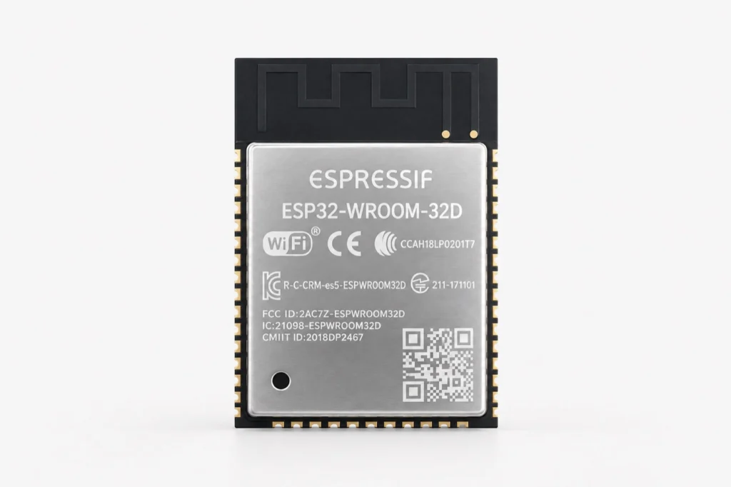
ESP32-WROOM-32D Pinout
The complete pin reference for the ESP-WROOM-32D module: 34 programmable GPIOs, ADC/DAC, touch, RTC and the exact pins you can safely reuse.
Read more
 Reference
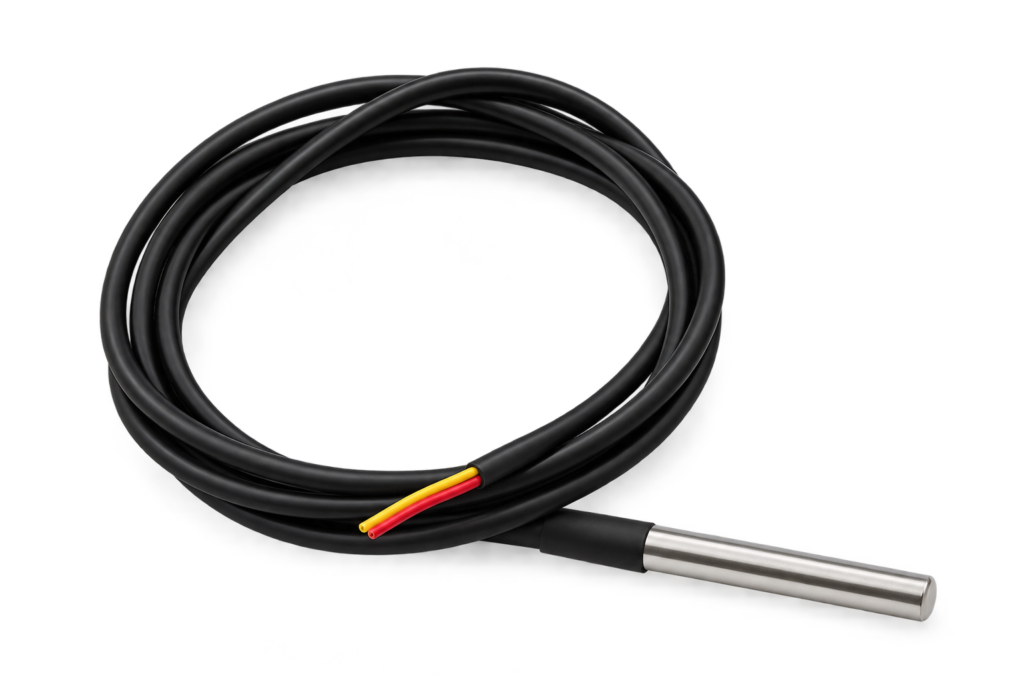
DS18B20 1-Wire Temperature Sensor
A rugged, waterproof-capable temperature sensor that can put dozens of measurement points on a single ESP32 GPIO. Covers how the 1-Wire bus and 64-bit ROM addressing work, the mandatory pull-up resistor, and parasite power mode.
Read more
 Reference
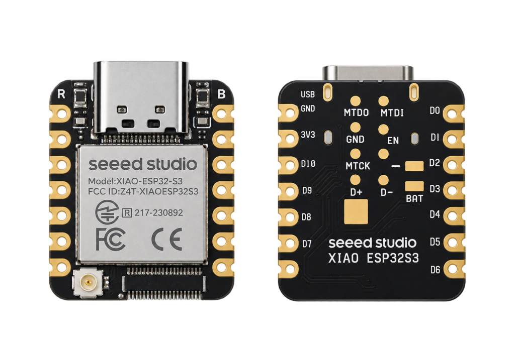
Seeed Studio XIAO ESP32S3 Pinout
The real pin reference for Seeed Studio's XIAO ESP32S3: thumbnail-sized, native USB, with a camera/display connector on the Sense variant.
Read more
More guides
Keep building.
From ESP32 HomeKit accessories to Arduino and ATtiny reference guides, there’s more where this came from.
All guides