OctoPrint® is a great solution for controlling your 3D printer. However, it’s missing one key function. You can’t turn the 3D printer on and off. Now that we have setup our OctoPrint® Server for multiple printers we are going to add this hardware and software feature.
Hardware
I assume you already have your OctoPrint® Server hardware and software ready, as I won’t be covering any of that here. If you don’t you can check my blog here. You’ll also need a double relay module board. The ones used for Arduino will work just fine.
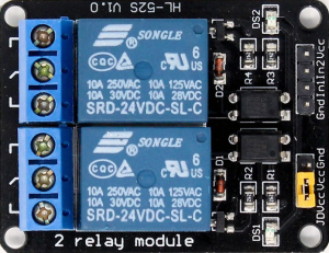
You’ll also need a power cord that will be cut but you can use the one your printer came with. Lastly, We’ll need a cable connecting the Raspberry Pi and the relay module. Before building anything I’d suggest making checking if the relay module will work with 3.3V. Power the relay board with 5.0V and use 3.3V signal to trigger it. You should hear click and the COM and NO pins should be shorted. Once the relay is working you can move on.
Cutting the PowerCord
In order to turn the printer on or off we’ll be using a relay to control the mains voltage. Since you’ll be working with the mains voltage you need to be really careful. I’m not responsible for any injury or damage you may cause!

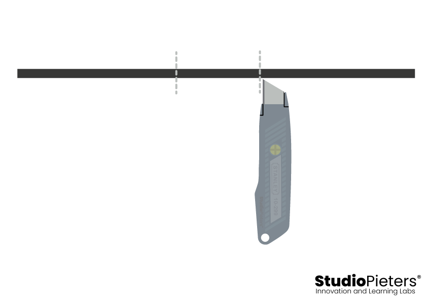
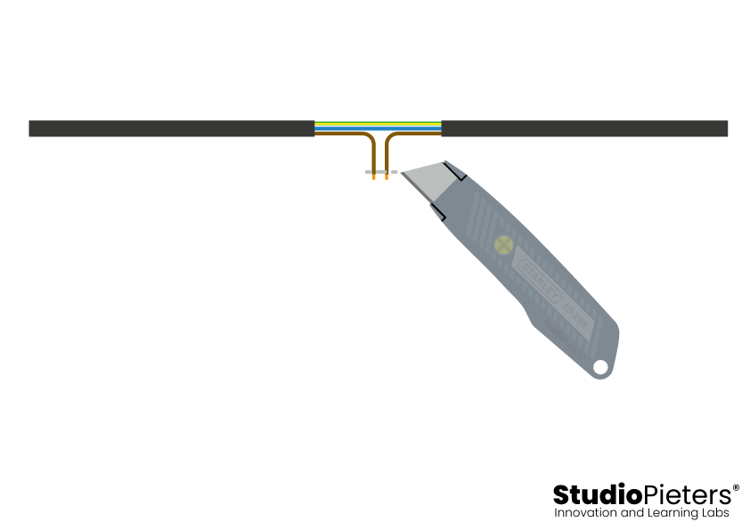
First, we need the power cord for the 3D printer. It should be the one shown in the picture. It might look slightly different but that’s fine. If you have power brick instead they usually have power cord like this as well. Or you can simply follow the instructions and replace the power cord with your DC power cable which is even better.

NOTE: Make sure the power cord is unplugged from the wall!
Remove about 5cm / 2inch of insulation. I’ve used Stanley knife to remove the insulation. All of my cuts were very shallow to assure I wouldn’t damage any of the wires inside. Simple make a shallow cut and then rip the insulation.
After removing the insulation you’ll see 3 wires inside. Make sure their insulation is OK if not you’ll need to get a new power cord.
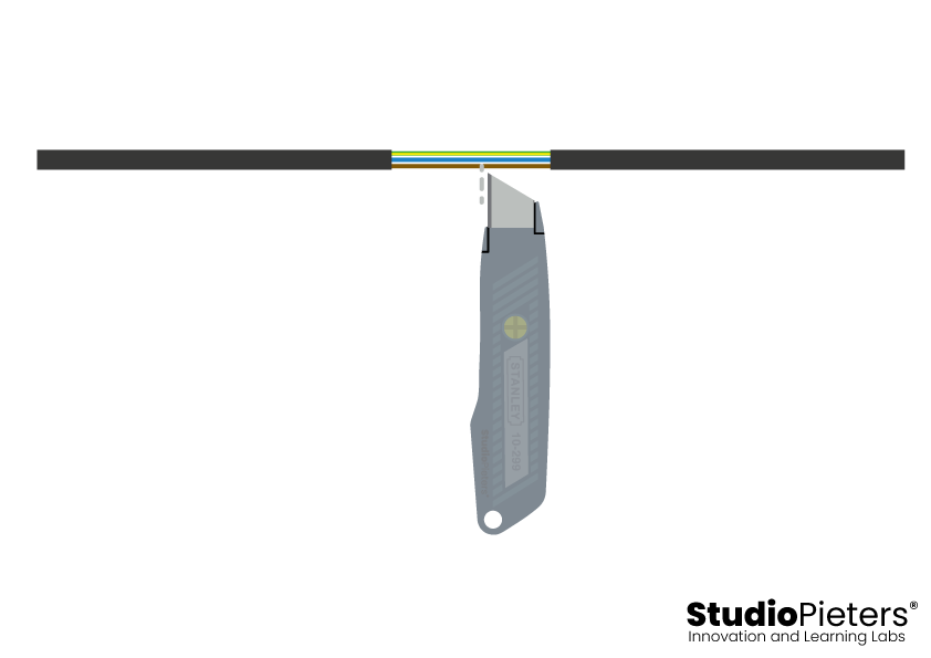
Cut the brown (black if it’s US plug) wire right in the middle and strip both ends.
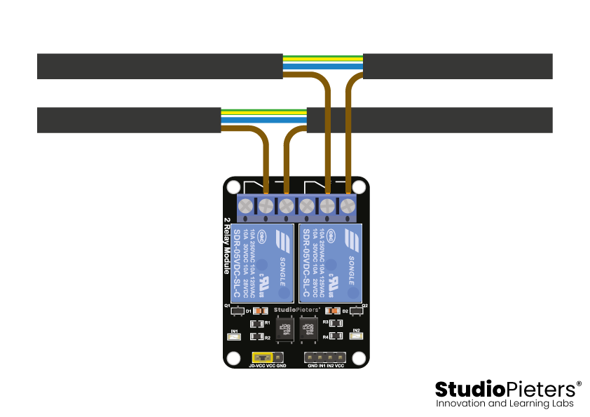
These two ends need to be screwed in a terminal on the relay board. One must be connected to the common pin(labeled C or COM) and the other to either the NO pin. NO stands for normally open. I’ve used NO which means the printer is only on when the relay is energized.
Connecting the Raspberry Pi
With the power cord hooked up, it’s time to connect the Raspberry Pi. The relay module has 3 pins: 5V, GND, and Signal. Intuitively the 5V and GND will be connected to the corresponding pins on the Raspberry Pi while the Signal can be connected to any GPIO pin. We’ll define the pin in the software later.
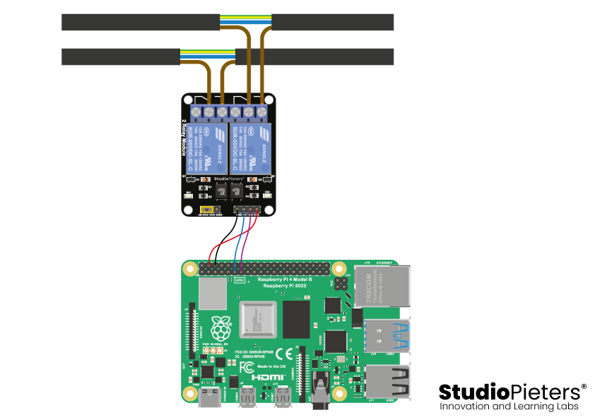
You can make your own cable to connect the Rapberry Pi and the relay module or an easier solution would be to simply use jumper wires, like I did. I would suggest using pin 11 (Signal | GPIO17), 4 (5V) and 6 (GND) as they are right next to each other yet they provide power. For the other relay you need another pin you can use pin 13 (Signal | GPIO27).
| Fuction | Name | Pin | Pin | Name | Fuction | ||
| Power | 3.3V | 1 | ● | ● | 2 | 5V | Power |
| SDA1 I2C | GPIO2 | 3 | ● | ● | 4 | 5V | Power |
| SCL1 I2C | GPIO3 | 5 | ● | ● | 6 | Ground | |
| GPIO_GCLK | GPIO4 | 7 | ● | ● | 8 | GPIO14 | UART0_TXD |
| Ground | 9 | ● | ● | 10 | GPIO15 | UART0_RXD | |
| GPIO17 | 11 | ● | ● | 12 | GPIO18 | PCM_CLK | |
| GPIO27 | 13 | ● | ● | 14 | Ground | ||
| GPIO22 | 15 | ● | ● | 16 | GPIO23 | ||
| Power | 3.3V | 17 | ● | ● | 18 | GPIO24 | |
| SPI0_MOSI | GPIO10 | 19 | ● | ● | 20 | Ground | |
| SPI0_MISO | GPIO9 | 21 | ● | ● | 22 | GPIO25 | |
| SPI0_SCLK | GPIO11 | 23 | ● | ● | 24 | GPIO8 | SPI0_CE0_N |
| Ground | 25 | ● | ● | 26 | GPIO7 | SPI0_CE1_N | |
| I2C ID EEPROM | ID_SD | 27 | ● | ● | 28 | ID_SC | I2C ID EEPROM |
| GPIO5 | 29 | ● | ● | 30 | Ground | ||
| GPIO6 | 31 | ● | ● | 32 | GPIO12 | ||
| GPIO13 | 33 | ● | ● | 34 | Ground | ||
| GPIO19 | 35 | ● | ● | 36 | GPIO16 | ||
| GPIO26 | 37 | ● | ● | 38 | GPIO20 | ||
| Ground | 39 | ● | ● | 40 | GPIO21 |
Software
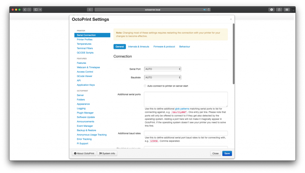
Now that the Hardware is ready we can go to the software part. Fortunately installing the software is really easy as we’ll be using a pre-existing plugin. Open the Octoprint in your browser and log in.

Next, click the settings icon (wrench).
Now choose the plugin manager on the left-hand side.
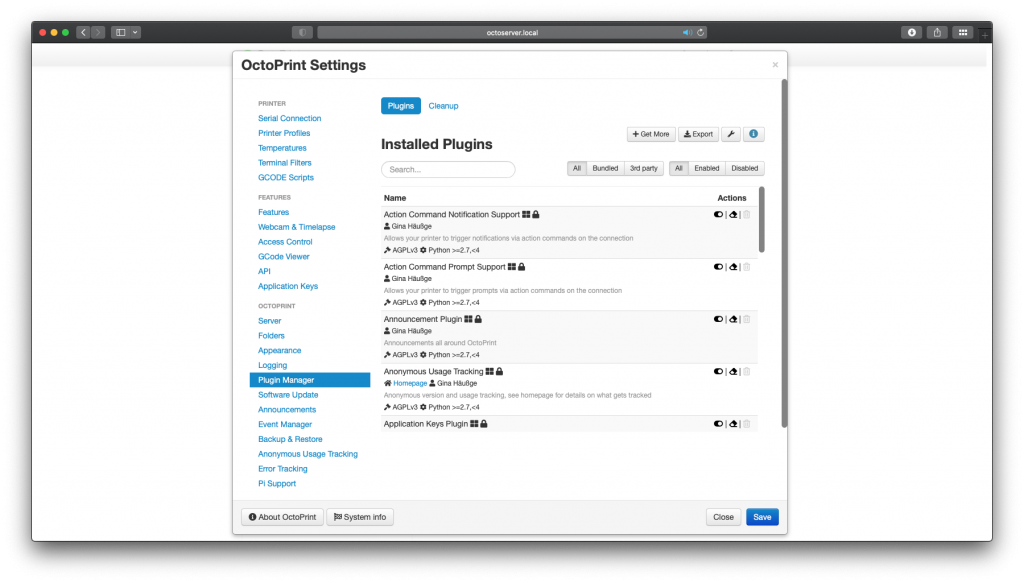
You’ll see a list of plugins but you need to select the + get more button on the top.
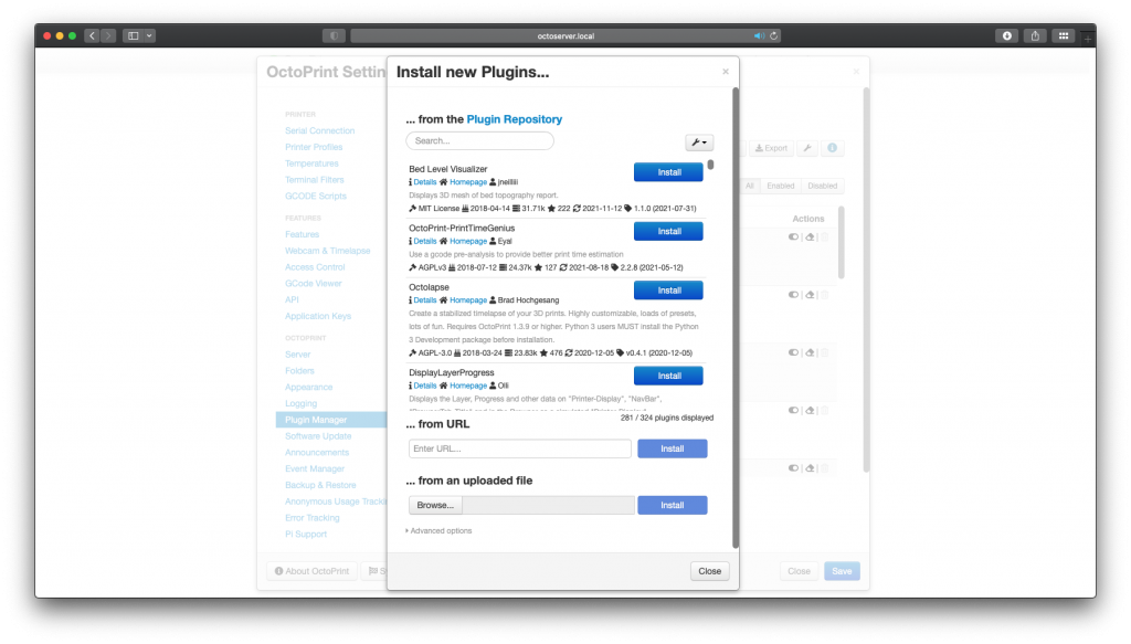
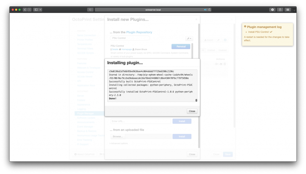
Then simply search for PSU Control.
At this point, you should see PSU control plugin submitted by Shawn Bruce.
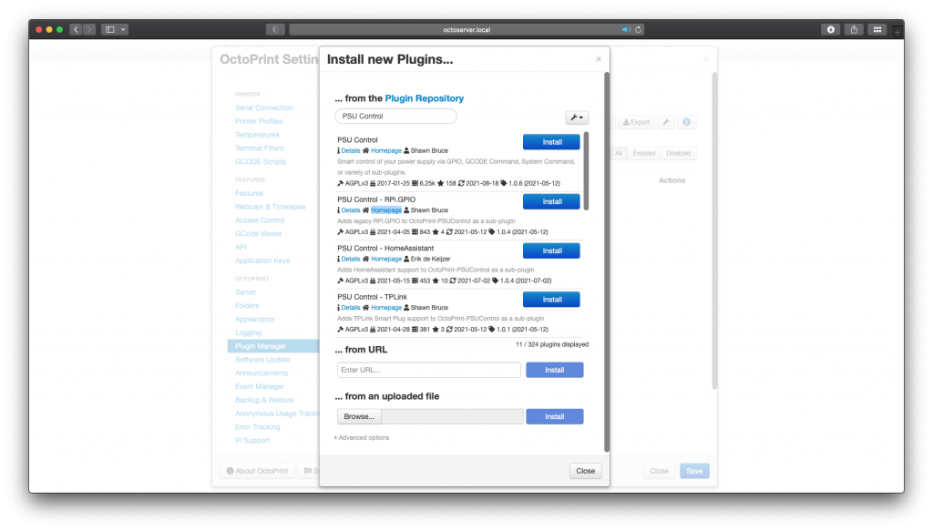
Go ahead and install it.
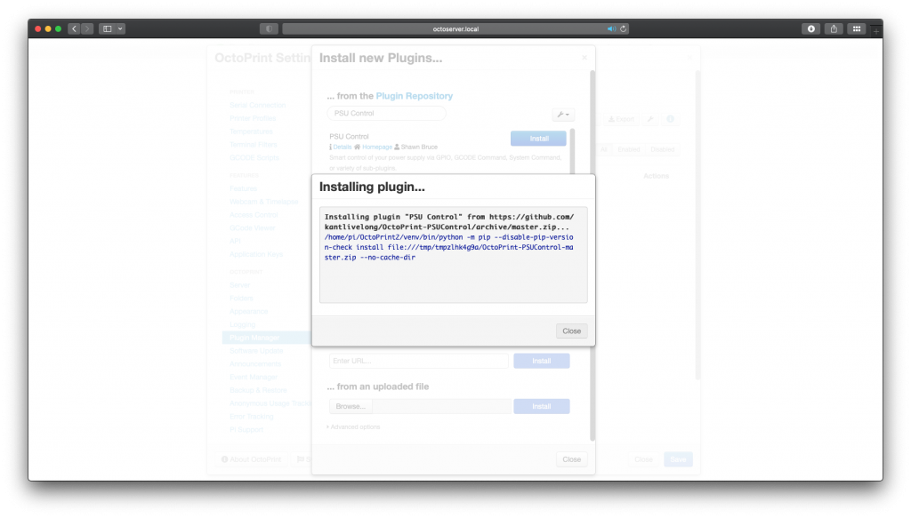
It will take few minutes and afterward you’ll be prompted to restart your Octoprint.
Hardware pin
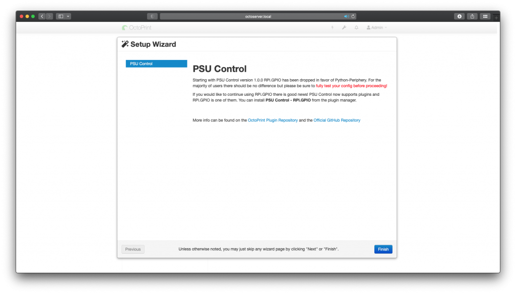
After the reboot, the PSU Control plugin setup wizard let’s you know that the installation was a succes. Click Finish.
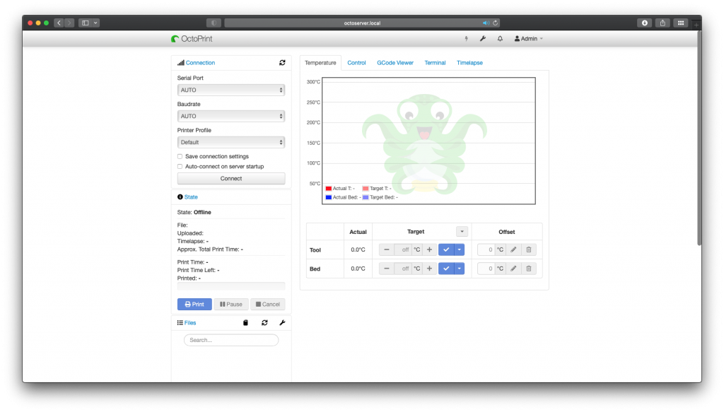
Now that the PSU Control plugin is installed and you’ll see lightning bolt icon on the top bar. We are not done yet, few things need to be set up.
Go to settings and on the left-hand side select the new PSU control option.
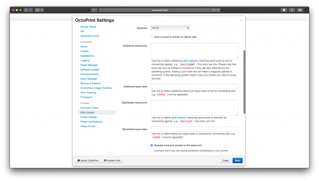
Now you see the PCU Control setting pane.
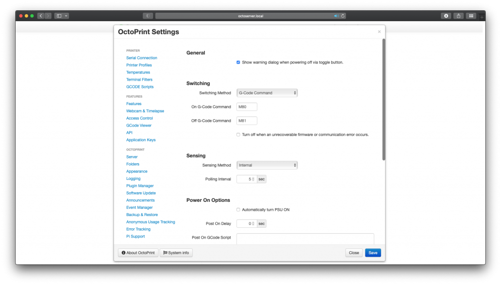
Remove the tick before Show warning dialog….

Choose switching method to GPIO.
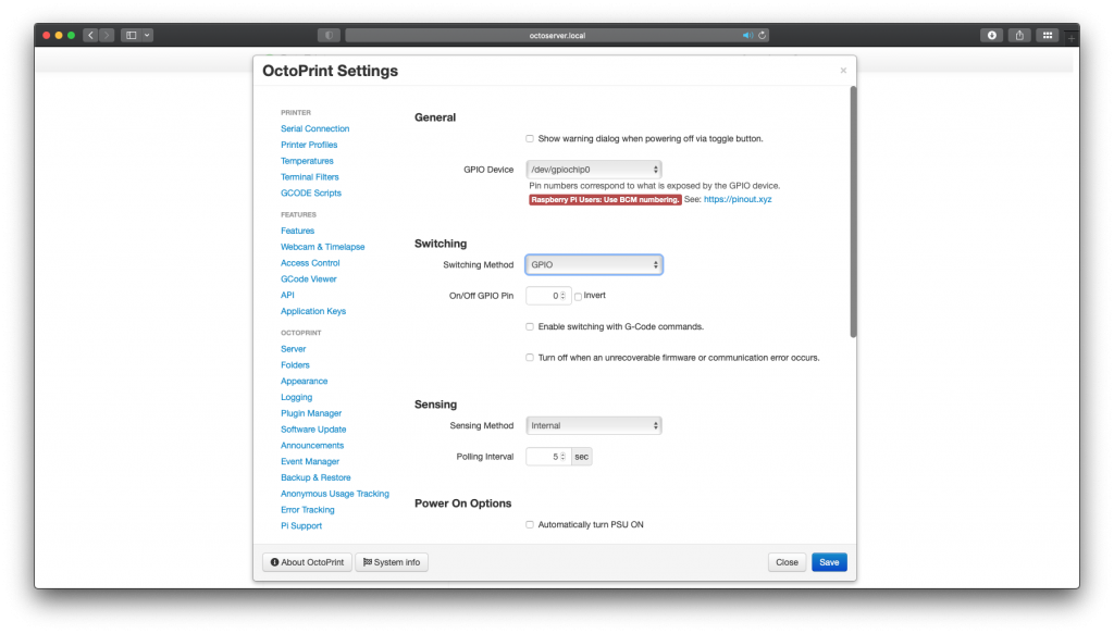
If you used the GPIO’s 17 and 27 on your pi as I suggested then for the On/Off GPIO Pin enter 17 for the first Octoprint setup.

And 27 for the other octoprint setup. If you used any other pins then here you’ll select which pin is being used as the signal for the relay.
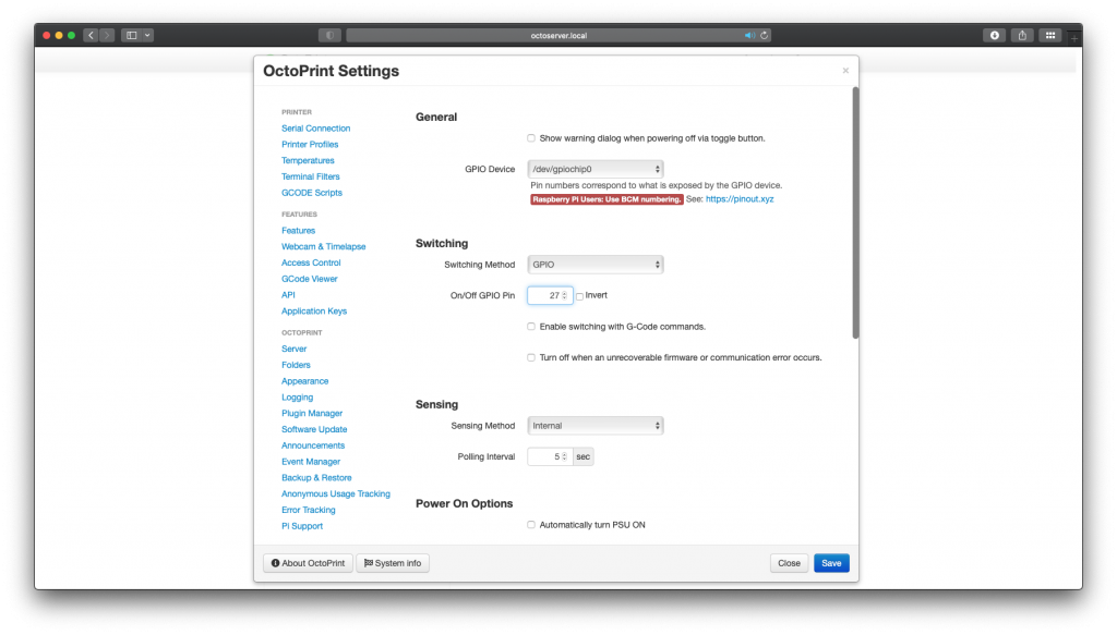
The remaining setting can be left at default. Now press Save.

Enclosure
We’re almost done. Now would be a good time to see if you can control the relay. Leave the power cord unplugged and simply have the relay module connected to the Pi. From the web interface turn the power on and off couple of times and you should hear the relay click each time. If not check the wiring and make sure the relay module is working. you can also check if the GPIO pin voltage is changing.
Last but not least is to add cover for the relay module. Don’t even think about plugging the power cord in without any sort of cover. There is exposed mains voltage on the board.
TESTING THE Octoprint – PSU Control HARDWARE
Now you can test if everything is working as it should. First turn on the Raspberry Pi, wait until is is fully start up. Then turn on the Octoprint 1 setup. Hereafter the octoprint 2 setup. Here is an animation of what should happen.