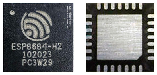
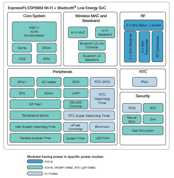
ESPC2-02 Wi-Fi and BLE coexistence Module is a highly integrated single-chip low power 802.11bgn Wireless LAN (WLAN) network controller. It combines a RISC CPU, WLAN MAC, a 1T1R capable WLAN baseband, RF, and Bluetooth in a single chip. It also provides a bunch of configurable GPIO, which are configured as digital peripherals for different applications and control usage. ESPC2-02 Module use ESP8684 as Wi-Fi and BLE coexistence SOC chip.
ESPC2-02 Module integrates internal memories for complete Wi-Fi protocol functions. The embedded memory configuration also provides convenient application developments. ESPC2-02 module supports the standard IEEE802.11 b/g/n/e/i protocol and the complete TCP/IP
protocol stack. The user can use it to add the Wi-Fi function for the installed devices, and also can be viewed as an independent network controller. Anyway, ESPC2-02 Wi-Fi module provides many probabilities with the best price.
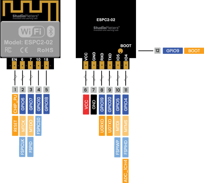
ESP8684 – Interface
The ESP8684 peripherals include:
- 8 × programmable GPIO’s
- UART/SDIO/SPI/I2C/GPIO/PWM
- LED PWM controller
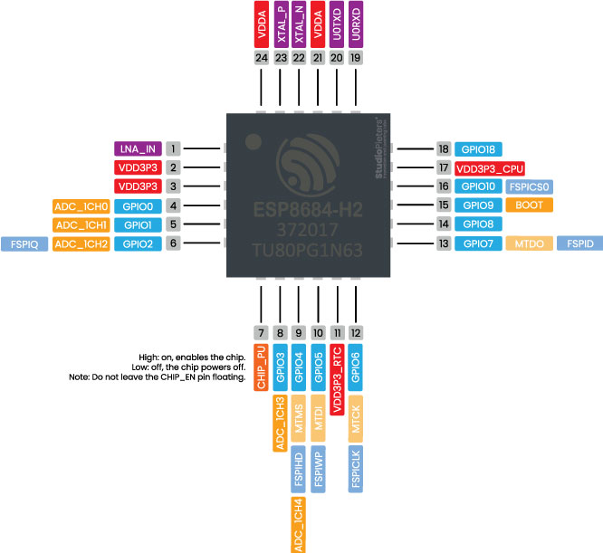
The ADC (analogue to digital converter) and DAC (digital to analogue converter) features are assigned to specific static pins. However, you can decide which pins are UART, I2C, SPI, PWM, etc. – you just need to assign them in the code. This is possible due to the ESP8684 chip’s multiplexing feature.
Additionally, there are pins with specific features that make them suitable or not for a particular project. The following table shows what pins are best to use as inputs, outputs and which ones you need to be cautious.

The pins highlighted in green are OK to use. The ones highlighted in yellow are OK to use, but you need to pay attention because they may have an unexpected behavior, mainly at boot. The pins highlighted in red are not recommended to use as inputs or outputs.
| GPIO | Input | Output | Notes |
| EN | — | — | Chip enable; Internal Pull-up. HIGH: enable the chip |
| 4 | OK | OK | MTMS, GPIO4, ADC1_CH4, FSPIHD |
| 5 | OK | OK | MTDI, GPIO5, FSPIWP |
| 6 | OK | OK | MTCK, GPIO6, FSPICLK |
| 7 | OK | OK | MTDO, GPIO7, FSPID |
| 9 | OK | OK | GPIO9 |
| 10 | OK | OK | GPIO10, FSPICS0 |
| 18 | OK | OK | GPIO18 |
| 19 | OK | OK | U0RXD, GPIO19 |
| 20 | OK | OK | U0TXD, GPIO20 |
Note
- Strapping pin: GPIO9 is a strapping pin.
- JTAG: GPIO5-7 are typically used for inline debug.

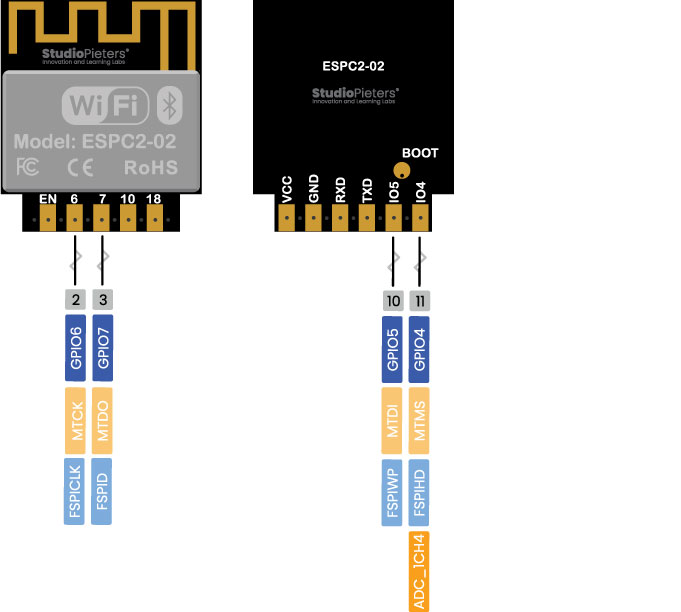
SPI
ESPC2-02 integrates one general purpose SPI controller which can be used as slave nodes driven by an off-chip SPI master.
- GPIO 4 (CS)
- GPIO 5 (MOSI)
- GPIO 6 (SCK)
- GPIO 7 (MISO)
Strapping Pins
The ESPC2-02 chip has the following strapping pin:
- GPIO 9
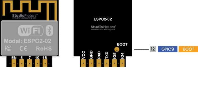
During the chip’s system reset (power-on-reset, RTC watchdog reset, brownout reset, analog super watchdog reset, and crystal clock glitch detection reset), the latches of the strapping pins sample the voltage level as strapping bits of ”0” or ”1”, and hold these bits until the chip is powered down or shut down.
GPIO8, and GPIO9 are connected to the chip’s internal weak pull-up/pull-down during the chip reset. Consequently, if they are unconnected or the connected external circuit is high-impedance, the internal weak pull-up/pull-down will determine the default input level of these strapping pins.
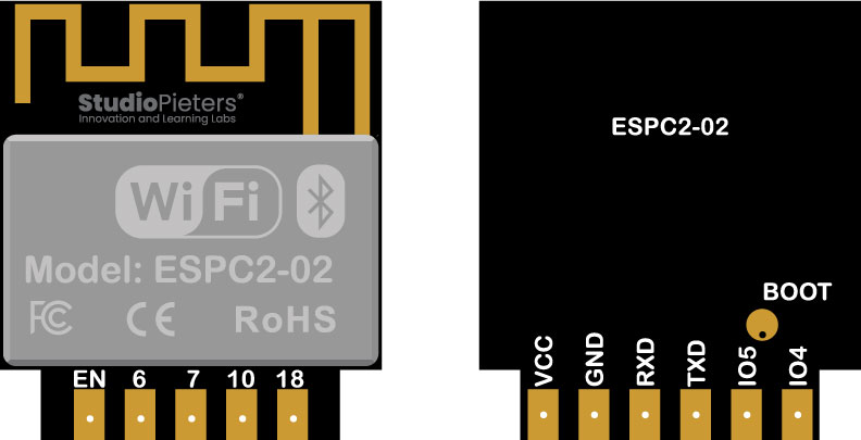
Enable (EN / CHIP_PU)
Enable (EN / CHIP_PU) is the 3.3V regulator’s enable pin. It’s pulled up, so connect to ground to disable the 3.3V regulator. This means that you can use this pin connected to a pushbutton to restart your ESPC2-02, for example.
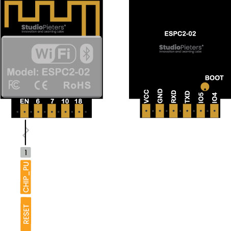
esptool.py resets ESPC2-02 automatically by asserting DTR and RTS control lines of the USB to serial converter chip, i.e., FTDI or CP210x (for more information, see Establish Serial Connection with ESPC2-02). The DTR and RTS control lines are in turn connected to GPIO0 and CHIP_PU (EN) pins of ESPC2-02, thus changes in the voltage levels of DTR and RTS will boot ESPC2-02 into Firmware Download mode.
GPIO current drawn
The absolute maximum current drawn per GPIO is 40mA according to the “Recommended Operating Conditions” section in the ESPC2-02 datasheet.

Overview
The ESP8684 Microcontroller is one of the most versatile boards on the market today, and that’s why we decided to focus on it in this guide. This guide displays most of its capabilities, but there are also more advanced options, which we did not go into in this post.
The important thing to know when you choose a board for your project is its capabilities and limitations. It’s also essential to understand the different communication protocols that the board uses. Of course, you don’t need to remember all of this information, you can always go back to this post and read the relevant information for you (this is a good time to bookmark this Blog btw).
Reference:
espressif, user guide, https://docs.espressif.com/projects/espressif-esp-dev-kits/en/latest/esp8684/esp8684-devkitm-1/user_guide.html espressif, datasheet, https://www.espressif.com/sites/default/files/documentation/esp8684_datasheet_en.pdf espressif, technica, https://www.espressif.com/en/support/documents/technical-documents?keys=8684 download.bl602, ESPC2_02, http://download.bl602.fun/ESPC2_02_User_Manual.pdf espressif, hardware design, https://www.espressif.com/sites/default/files/documentation/esp8684_hardware_design_guidelines_en.pdf