
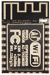
ESP8266
The modules are based on a small board with an antenna at the top and smd tabs along the sides and one end. The tabs are spaced in millimetres, so are not compatible with common header pins, breadboards and so on. So, if you are not surface mounting them to a customised pcb, the best option is to use the module with a breakout board, which will then equip it with standard headers. To do this, buy the module with breakout board kit, which you can also get ready soldered and tested for you to use. The breakout pins will plug into a breadboard or you can connect with Dupont Leads.
Data transfer and upload
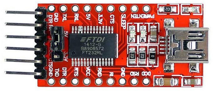
Uploading data to the ESP8266 is done using serial data. This means that to connect it to a computer (MAC or PC) you will need to use a USB to Serial module such as an FTDI breakout board.
Note: FTDI is not the only kind of chip for serial to USB data transfer, there are others such as the CH340G and you may need to install drivers if they do not work automatically.
To program the ESP8266 it will need to be put into UART programming mode. This involves pulling down GPIO pin 0 to ground via a resistor. During an upload the module will need to reset, change to programming mode and then change back to normal operating mode. This can either be done manually with a couple of push buttons, or can be automated using connections from the USB-Serial adaptor and a few extra components.
To upload the data, connect Rx to Tx and Tx to Rx between the two boards. Also, connect the GND of the programming module to the GND of the ESP8266. For Auto reset programming, connect RTS and DTR from the programmer to the ESP8266 as shown in the circuit below, if these are not available you will need to use the Manual Reset circuitry and method. Whichever method you choose, it is a good idea to have a reset button connected as well, so you can just start a program running again if you need to.

Basic Setup
To set up the ESP8266 for use as a microcontroller or WiFi solution, it will need some extra components, such as resistors to set some of the pins either high or low. Two push buttons and some DuPont wires.
| PIN 8 | VCC | 3.3V |
| PIN 25 | GND | GND |
| PIN 3 | CH-PD connects with a 10KΩ resistor to | 3.3V |
| PIN 1 | RESET connects with a 10KΩ resistor to | 3.3V |
| PIN 18 | GPIO0 connects with a 10KΩ resistor to | 3.3V |
| PIN 16 | GPIO15 connects with a 10KΩ resistor to | GND |
| PIN 18 | Via GND to push button switch (program button) | GND |
| PIN 1 | Via GND to push button switch (reset button) | GND |
Circuit

Scheme

Manual reset and manual program
- press and hold the reset button
- press and hold the program button
- release the reset button, the ESP will boot in program mode
- release the program button
- upload the code
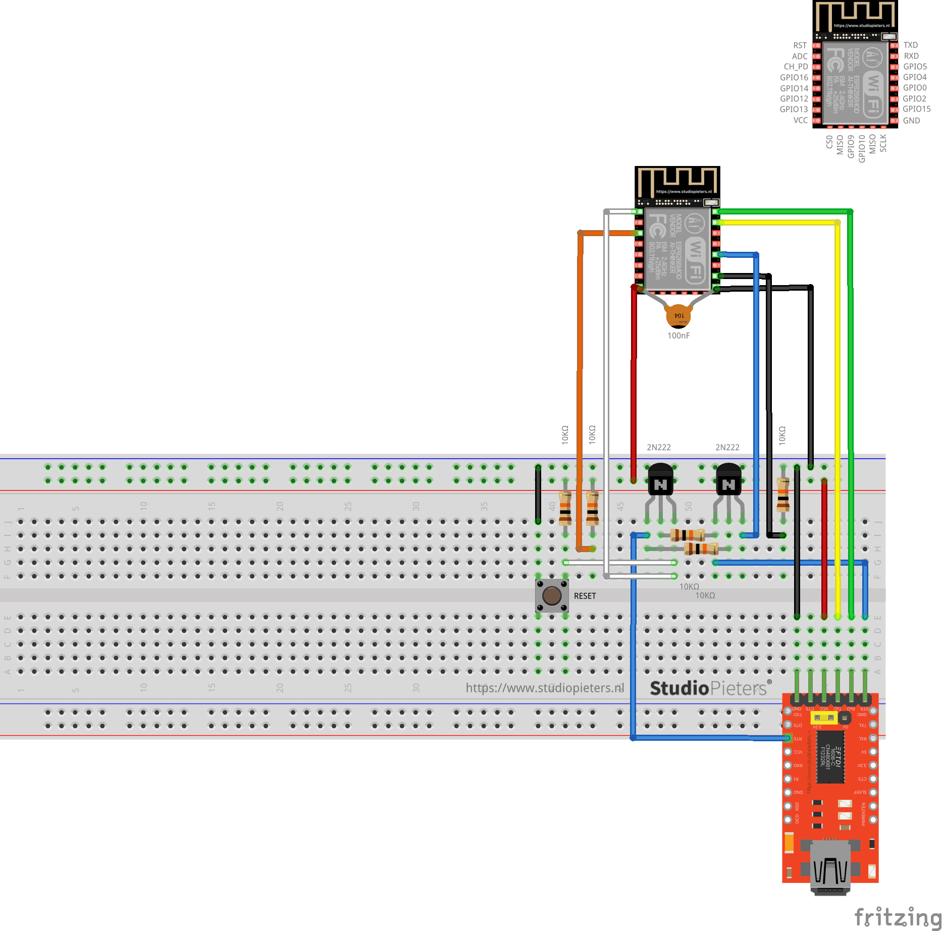
Automatic Program & Reset
There is also an automatic method for uploading and resetting. To use this, some additional circuitry will be needed using a couple of small NPN transistors.
| PIN 8 | VCC | 3.3V |
| PIN 15 | GND | GND |
| PIN 3 | CH-PD connects with a 10KΩ resistor to | 3.3V |
| PIN 1 | RESET connects with a 10KΩ resistor to | 3.3V |
| PIN 18 | GPIO0 connects with a 10KΩ resistor to | 3.3V |
| PIN 16 | GPIO15 connects with a 10KΩ resistor to | GND |
| PIN 1 | Via GND to push button switch (reset button) | GND |
| PIN 1 | Via transitor (Q1) to FTDI Module | – |
| PIN 18 | Via transitor (Q2) to FTDI Module | – |
Circuit


Scheme
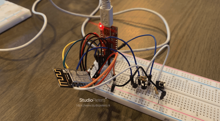
Testing the setup
I build the scheme like here above. Then I used the esptool.py to flash your device. First, erase flash:
esptool.py erase_flash
Normally, your ESPPort will be something like /dev/cu.usbserial-A50285BI. Then, set your device in flash-mode again, and flash the new firmware:
esptool.py -p /dev/cu.usbserial-A50285BI --baud 115200 write_flash -fs 1MB -fm dout -ff 40m 0x0 rboot.bin 0x1000 blank_config.bin 0x2000 otaboot.bin
Yes I worked perfectly!

REFERENCE
Espressif Systems, esptool (2021), ESP8266 and ESP32 serial bootloader utility, https://github.com/espressif/esptool Q26, ESP8266 (2021), The ESP8266 chip is packaged in a series of modules as well as development boards.y, https://www.q26.co.uk