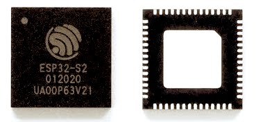
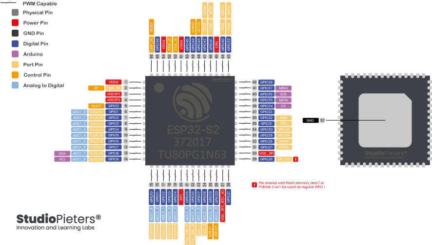
In this post, we’ll be taking a closer look at the ESP32-S2 hardware, and more specifically, the ESP32-S2 Mini pinout. The ESP32-S2 is based on the Xtensa® single-core 32-bit LX7 microprocessor, up to 240 MHz. The ESP32-S2 pinout consists of 43 × programmable GPIO’s pins, 2 × 12-bit SAR ADCs, up to 20 channels. The versatility of the pinout provides many options such as driving motors, LED’s, reading sensors and more. In this post, we’ll go over the capabilities of the ESP32-S2 pinout.
ESP32-S2 Peripherals
The ESP32 peripherals include:
- 43 × programmable GPIO’s
- 2 × 12-bit SAR ADCs, up to 20 channels
- 2 × 8-bit DAC
- 14 × touch sensing IO’s
- 4 × SPI
- 1 × I2S
- 2 × I2C
- 2 × UART
- RMT (TX/RX)
- LED_PWM, up to 8 channels
- 1 × full-speed USB OTG
- 1 × temperature sensor
- 1 × DVP 8/16 camera interface, implemented using the hardware resources of I2S
- 1 × LCD interface (8-bit serial RGB/8080/6800), implemented using the hardware resources of SPI2
- 1 × LCD interface (8/16/24-bit parallel), implemented using the hardware resources of I2S
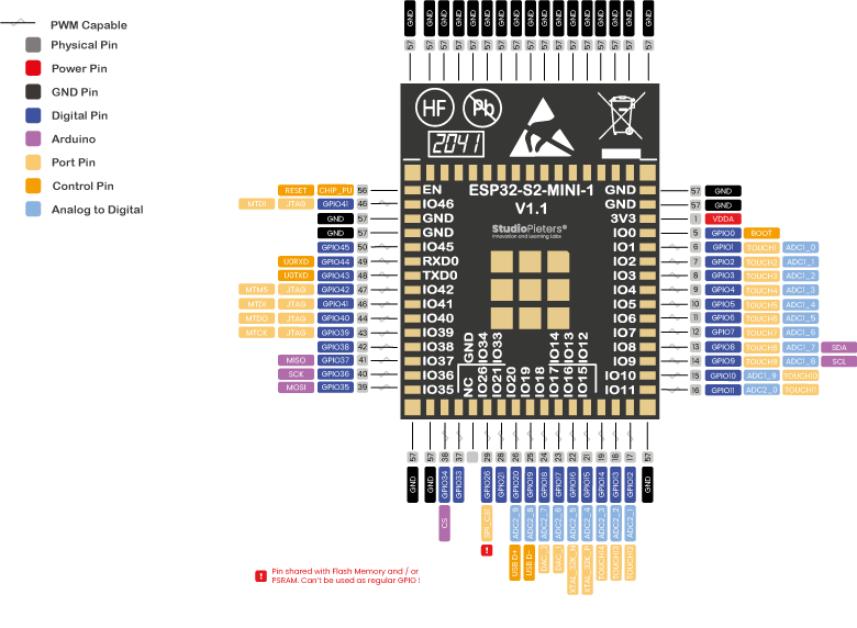
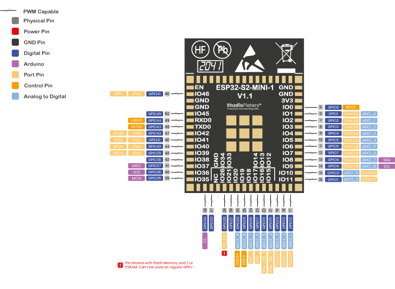
The ADC (Analogue to Digital Converter) and DAC (Digital to Analogue Converter) features are assigned to specific static pins. However, you can decide which pins are UART, I2C, SPI, PWM, etc – you just need to assign them in the code. This is possible due to the ESP32 chip’s multiplexing feature. Because not everybody works with the FQN of this chip as shown below, we use the MCU version as reference.

ESP32-S2 MINI 1
At the core of the ESP32-S2-MINI modules is ESP32-S2FH4, a Xtensa 32-bit LX7 CPU that operates at up to 240MHz. This chip has a low-power co-processor that can be used instead of the CPU, in order to save power while performing tasks that do not require much computing power, such as the monitoring of peripherals. ESP32-S2FH4 has up to 43 GPIO’s and integrates various peripherals, such as SPI, I2S, UART, I2C, LED PWM, LCD, camera interface, ADC, DAC, touch sensor and temperature sensor. ESP32-S2FH4 also includes a full-speed USB On-The-Go (OTG) interface which enables USB communication in any place, at any time. The ESP32-S2 mini 1 has a small footprint. To illustrate how small, I made a comparison between an SD card adapter and an SD card.
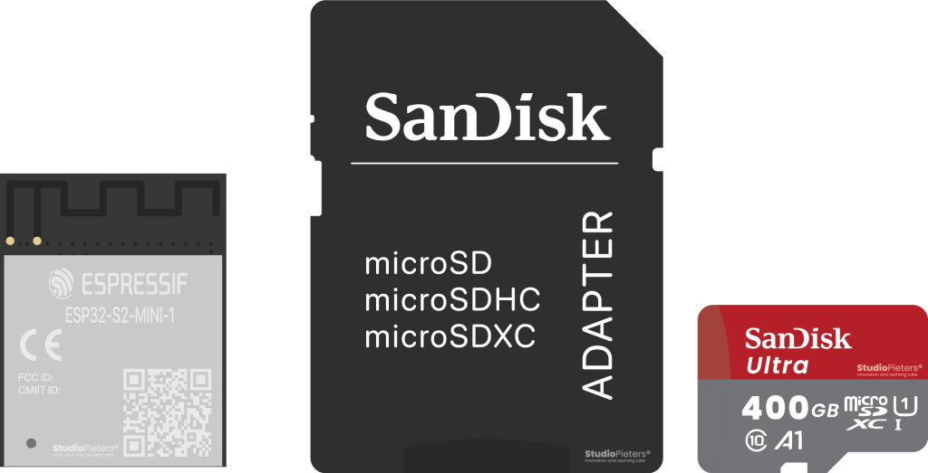
ESP32-S2 mini 1 Dimensions: 19.00 mm x 13.20 mm x 2.40 mm
But how did they make this in this format you ask, well with no external flash, the module can be made smaller with the flash embedded inside the processor.
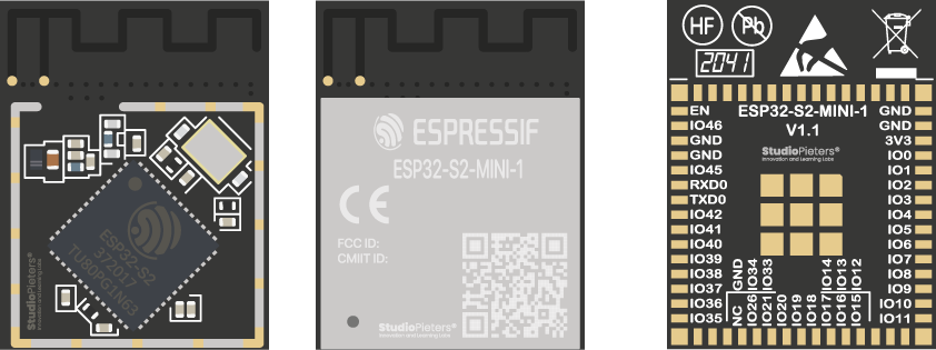
The module has 65 pins. Which are described below.
| Pin Name | No. | Type | Function Description |
| GND | “1, 2,30,42,43,46-65” | P | Ground |
| 3V3 | 3 | P | Power supply |
| IO0 | 4 | I/O/T | “RTC_GPIO0, GPIO0” |
| IO1 | 5 | I/O/T | “RTC_GPIO1, GPIO1, TOUCH1, ADC1_CH0” |
| IO2 | 6 | I/O/T | “RTC_GPIO2, GPIO2, TOUCH2, ADC1_CH1” |
| IO3 | 7 | I/O/T | “RTC_GPIO3, GPIO3, TOUCH3, ADC1_CH2” |
| IO4 | 8 | I/O/T | “RTC_GPIO4, GPIO4, TOUCH4, ADC1_CH3” |
| IO5 | 9 | I/O/T | “RTC_GPIO5, GPIO5, TOUCH5, ADC1_CH4” |
| IO6 | 10 | I/O/T | “RTC_GPIO6, GPIO6, TOUCH6, ADC1_CH5” |
| IO7 | 11 | I/O/T | “RTC_GPIO7, GPIO7, TOUCH7, ADC1_CH6” |
| IO8 | 12 | I/O/T | “RTC_GPIO8, GPIO8, TOUCH8, ADC1_CH7” |
| IO9 | 13 | I/O/T | “RTC_GPIO9, GPIO9, TOUCH9, ADC1_CH8, FSPIHD” |
| IO10 | 14 | I/O/T | “RTC_GPIO10, GPIO10, TOUCH10, ADC1_CH9, FSPICS0, FSPIIO4” |
| IO11 | 15 | I/O/T | “RTC_GPIO11, GPIO11, TOUCH11, ADC2_CH0, FSPID, FSPIIO5” |
| IO12 | 16 | I/O/T | “RTC_GPIO12, GPIO12, TOUCH12, ADC2_CH1, FSPICLK, FSPIIO6” |
| IO13 | 17 | I/O/T | “RTC_GPIO13, GPIO13, TOUCH13, ADC2_CH2, FSPIQ, FSPIIO7” |
| IO14 | 18 | I/O/T | “RTC_GPIO14, GPIO14, TOUCH14, ADC2_CH3, FSPIWP, FSPIDQS” |
| IO15 | 19 | I/O/T | “RTC_GPIO15, GPIO15, U0RTS, ADC2_CH4, XTAL_32K_P” |
| IO16 | 20 | I/O/T | “RTC_GPIO16, GPIO16, U0CTS, ADC2_CH5, XTAL_32K_N” |
| IO17 | 21 | I/O/T | “RTC_GPIO17, GPIO17, U1TXD, ADC2_CH6, DAC_1” |
| IO18 | 22 | I/O/T | “RTC_GPIO18, GPIO18, U1RXD, ADC2_CH7, DAC_2, CLK_OUT3” |
| IO19 | 23 | I/O/T | “RTC_GPIO19, GPIO19, U1RTS, ADC2_CH8, CLK_OUT2, USB_D-“ |
| IO20 | 24 | I/O/T | “RTC_GPIO20, GPIO20, U1CTS, ADC2_CH9, CLK_OUT1, USB_D+” |
| IO21 | 25 | I/O/T | “RTC_GPIO21, GPIO21” |
| IO26 | 26 | I/O/T | “SPICS1, GPIO26” |
| NC | 27 | – | NC |
| IO33 | 28 | I/O/T | “SPIIO4, GPIO33, FSPIHD” |
| IO34 | 29 | I/O/T | “SPIIO5, GPIO34, FSPICS0” |
| IO35 | 31 | I/O/T | “SPIIO6, GPIO35, FSPID” |
| IO36 | 32 | I/O/T | “SPIIO7, GPIO36, FSPICLK” |
| IO37 | 33 | I/O/T | “SPIDQS, GPIO37, FSPIQ” |
| IO38 | 34 | I/O/T | “GPIO38, FSPIWP” |
| IO39 | 35 | I/O/T | “MTCK, GPIO39, CLK_OUT3” |
| IO40 | 36 | I/O/T | “MTDO, GPIO40, CLK_OUT2” |
| IO41 | 37 | I/O/T | “MTDI, GPIO41, CLK_OUT1” |
| IO42 | 38 | I/O/T | “MTMS, GPIO42” |
| TXD0 | 39 | I/O/T | “U0TXD, GPIO43, CLK_OUT1” |
| RXD0 | 40 | I/O/T | “U0RXD, GPIO44, CLK_OUT2” |
| IO45 | 41 | I/O/T | GPIO45 |
| IO46 | 42 | I | GPIO46 |
| EN | 45 | I | “Hign: on, enables the chip. Low: off, the chip powers off.” |
| Note: Do not leave the EN pin floating |
Power Supply
The GND pins are used to close the electrical circuit and provide a common logic reference level throughout your circuit. Always make sure that all GND’s (of the Arduino, peripherals and components) are connected to one another and have a common ground.
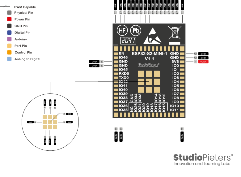
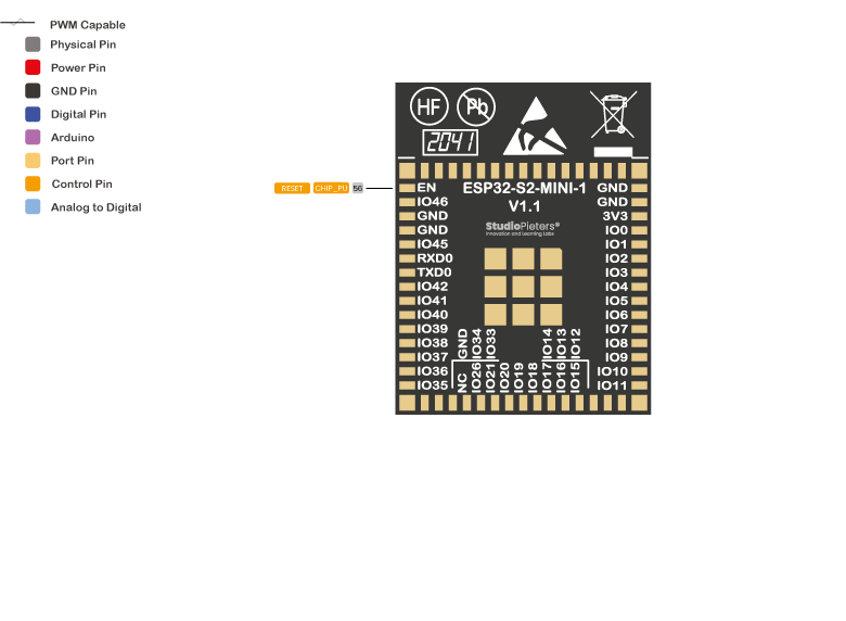
You can find 1 reset pin on the ESP32-S2-MINI, CHIP_PU serves as the reset pin of the ESP32-S2-MINI.
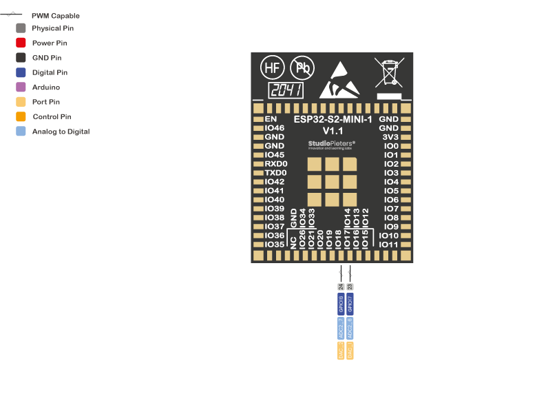
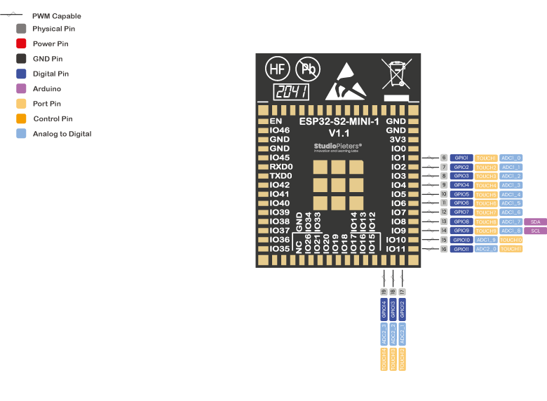
Analogue
ESP32-S2 family integrates two 13-bit SAR ADCs and supports measurements on 20 channels (analogue enabled
pins) (while the ESP8266 only has 1x 10 bits ADC). These are the GPIO’s that can be used as ADC and respective channels.
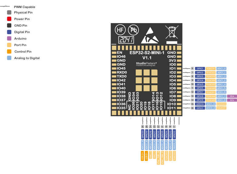
Analogue to Digital Conversion
ADC stands for Analogue to Digital Converter. ADC is an electronic circuit used to convert analogue signals into digital signals. This digital representation of analogue signals allows the processor (which is a digital device) to measure the analogue signal and use it through its operation. The ESP32 Pin’s ADC1_X and ADC2_X are capable of reading analogue voltages. The ADC converts voltage into bits which the microprocessor can understand.
- GPIO1 ADC1_CH0
- GPIO2 ADC1_CH1
- GPIO3 ADC1_CH2
- GPIO4 ADC1_CH3
- GPIO5 ADC1_CH4
- GPIO6 ADC1_CH5
- GPIO7 ADC1_CH6
- GPIO8 ADC1_CH7
- GPIO9 ADC1_CH8
- GPIO10 ADC1_CH9
- GPIO11 ADC2_CH0
- GPIO12 ADC2_CH1
- GPIO13 ADC2_CH2
- GPIO14 ADC2_CH3
- GPIO15 ADC2_CH4
- GPIO16 ADC2_CH5
- GPIO17 ADC2_CH6
- GPIO18 ADC2_CH7
- GPIO19 ADC2_CH8
- GPIO20 ADC2_CH9
Note: ADC2 pins cannot be used when Wi-Fi is used. So, if you’re using Wi-Fi, and you’re having trouble getting the value from an ADC2 GPIO, you may consider using an ADC1 GPIO instead, that should solve your problem.
The ADC input channels have a 12 bit resolution. This means that you can get analogue readings ranging from 0 to 4095, in which 0 corresponds to 0V and 4095 to 3.3V. You also have the ability to set the resolution of your channels on the code, as well as the ADC range.
The ESP32 ADC pins don’t have a linear behaviour. You probably won’t be able to distinguish between 0 and 0.1V, or between 3.2 and 3.3V. You need to keep that in mind when using the ADC pins.
Digital Pins
All the ESP32-S2-MINI serve as digital input/output pins.
Note: Each pin can provide up to 40 mA max. But the recommended current is 20 mA. The absolute max current provided (or sank) from all pins together is 200mA.
Digital
Digital is a way of representing voltage in 1 bit: either 0 or 1. Digital pins on the ESP32-S2-MINI are pins designed to be configured as inputs or outputs according to the needs of the user. These pins are either on or off. When ON they are in a HIGH voltage state of 3.3V and when OFF they are in a LOW voltage state of 0V. When the digital pins are configured as output, they are set to 0 or 3.3 volts.
Between 0-3.3 volts, which is converted into digital representation (0 or 1). To determine this, there are 2 thresholds: Below 0.8v – considered as 0. Above 2v – considered as 1. When connecting a component to a digital pin, make sure that the logic levels match. If the voltage is in between the thresholds, the returning value will be undefined.
Input only pins
GPIO46 is a GPI – input only pins. These pins don’t have internal pull-ups or pull-down resistors. They can’t be used as outputs, so use these pins only as inputs:
- GPIO46
Digital to Analogue Converter (DAC)
There are 2 x 8 bits DAC channels on the ESP32 to convert digital signals into analogue voltage signal outputs. These are the DAC channels. DAC1 (GPIO25) and DAC2 (GPIO17).
PWM
In general, Pulse Width Modulation (PWM) is a modulation technique used to encode a message into a pulsing signal. A PWM comprises two key components: frequency and duty cycle. The PWM frequency dictates how long it takes to complete a single cycle (period) and how quickly the signal fluctuates from high to low. The duty cycle determines how long a signal stays high out of the total period. Duty cycle is represented in percentage.
On the ESP32-S2-MINI, the PWM enabled pins produce a constant frequency of ~ 500Hz, while the duty cycle changes according to the parameters set by the user. See the following illustration:
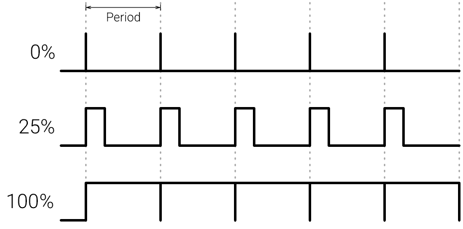
PWM signals are used for speed control of DC motors, dimming LED’s and more. The ESP32-S2-MINI PWM controller has 8 independent channels that can be configured to generate PWM signals with different properties. All pins that can act as outputs can be used as PWM pins. To set a PWM signal, you need to define these parameters in the code:
- Signal’s frequency;
- Duty cycle;
- PWM channel;
- GPIO where you want to output the signal.
Serial Communication
Serial communication is used to exchange data between the Arduino board and another serial device such as computers, displays, sensors and more. Each Arduino board has at least one serial port. Serial communication occurs on digital pins 0 (RX) and 1 (TX) as well as via USB. Arduino supports serial communication through digital pins with the Software Serial Library as well. This allows the user to connect multiple serial-enabled devices and leave the main serial port available for the USB.
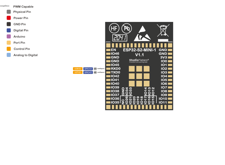
Software serial and hardware serial – Most microcontrollers have hardware designed to communicate with other serial devices. Software serial ports use a pin-change interrupt system to communicate. There is a built-in library for Software Serial communication. Software serial is used by the processor to simulate extra serial ports. The only drawback with software serial is that it requires more processing and cannot support the same high speeds as hardware serial.

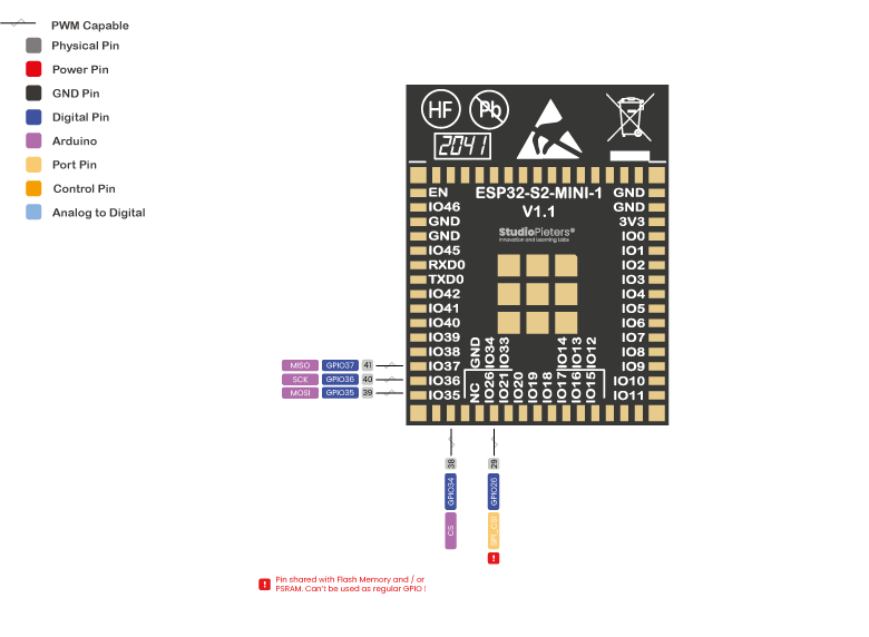
SPI
SPI – SS/SCK/MISO/MOSI pins are the dedicated pins for SPI communication. Serial Peripheral Interface (SPI) is a serial data protocol used by microcontrollers to communicate with one or more external devices in a bus like connection. The SPI can also be used to connect 2 microcontrollers. On the SPI bus, there is always one device that is denoted as a Master device and all the rest as slaves. In most cases, the microcontroller is the Master device. The SS (Slave Select) pin determines which device the Master is currently communicating with. SS/SCK/MISO/MOSI pins are the dedicated pins for SPI communication. SPI enabled devices always have the following pins:
MISO (Master In, Slave Out) – A line for sending data to the Master device
MOSI (Master Out, Slave In) – The Master line for sending data to peripheral devices
SCK (Serial Clock) – A clock signal generated by the Master device to synchronize data transmission.
SS (Slave Select) pin determines which device the Master is.
ESP32-S2 family features four SPI interfaces (SPI0, SPI1, SPI2 and SPI3). SPI0 and SPI1 can only be configured to operate in SPI memory mode; SPI2 can be configured to operate in SPI memory and general-purpose SPI modes; SPI3 can only be configured to operate in general-purpose SPI mode. Any GPIO can be set as SPI pin. For extended reference, see this link. Therefore, I used the Arduino pins as reference.
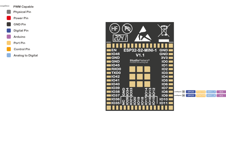
I2C
I2C is a communication protocol commonly referred to as the “I2C bus”. The I2C protocol was designed to enable communication between components on a single circuit board. With I2C there are 2 wires referred to as SCL and SDA. SCL/SDA pins are the dedicated pins for I2C communication.
SCL is the clock line which is designed to synchronize data transfers.
SDA is the line used to transmit data.
Each device on the I2C bus has a unique address, up to 255 devices can be connected on the same bus. The ESP32 has two I2C channels and any pin can be set as SDA or SCL. The default I2C pins are.
- GPIO 8 (SDA)
- GPIO 9 (SCL)
Interrupt
An external interrupt is a system interrupt that occurs when outside interference is present. Interference can come from the user or other hardware devices in the network. Common uses for these interrupts in ESP32-S2-MINI are reading the frequency of a square wave generated by encoders or waking up the processor upon an external event. On the ESP32-S2-MINI, all GPIO’s can be configured as interrupts.
Capacitive touch GPIO’s
The ESP32-S2-MINI has 14 internal capacitive touch sensors. These can sense variations in anything that holds an electrical charge, like the human skin. So they can detect variations induced when touching the GPIO’s with a finger. These pins can be easily integrated into capacitive pads, and replace mechanical buttons. The capacitive touch pins can also be used to wake up the ESP32 from deep sleep.
Those internal touch sensors are connected to these GPIO’s.
- GPIO1 TOUCH1
- GPIO2 TOUCH2
- GPIO3 TOUCH3
- GPIO4 TOUCH4
- GPIO5 TOUCH5
- GPIO6 TOUCH6
- GPIO7 TOUCH7
- GPIO8 TOUCH8
- GPIO9 TOUCH9
- GPIO10 TOUCH10
- GPIO11 TOUCH11
- GPIO12 TOUCH12
- GPIO13 TOUCH13
- GPIO14 TOUCH14

RTC GPIO’s
There is RTC GPIO support on the ESP32. The GPIO’s routed to the RTC low-power subsystem can be used when the ESP32 is in deep sleep. These RTC GPIO’s can be used to wake up the ESP32 from deep sleep when the Ultra Low Power (ULP) co-processor is running. The following GPIO’s can be used as an external wake-up source.
- GPIO0 RTC_GPIO0
- GPIO1 RTC_GPIO1
- GPIO2 RTC_GPIO2
- GPIO3 RTC_GPIO3
- GPIO4 RTC_GPIO4
- GPIO5 RTC_GPIO5
- GPIO6 RTC_GPIO6
- GPIO7 RTC_GPIO7
- GPIO8 RTC_GPIO8
- GPIO9 RTC_GPIO9
- GPIO10 RTC_GPIO10
- GPIO11 RTC_GPIO11
- GPIO12 RTC_GPIO12
- GPIO13 RTC_GPIO13
- GPIO14 RTC_GPIO14
- GPIO15 RTC_GPIO15
- GPIO16 RTC_GPIO16
- GPIO17 RTC_GPIO17
- GPIO18 RTC_GPIO18
- GPIO19 RTC_GPIO19
- GPIO20 RTC_GPIO20
- GPIO21 RTC_GPIO21

Strapping Pins
ESP32-S2 family has three strapping pins:
• GPIO0
• GPIO45
• GPIO46
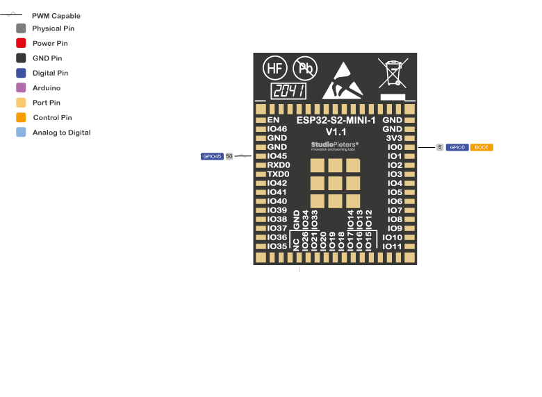
These are used to put the ESP32 into bootloader or flashing mode. On most development boards with built-in USB/Serial, you don’t need to worry about the state of these pins. The board puts the pins in the right state for flashing or boot mode.
However, if you have peripherals connected to those pins, you may have trouble trying to upload new code, flashing the ESP32 with new firmware or resetting the board. If you have some peripherals connected to the strapping pins, and you are getting trouble uploading code or flashing the ESP32, it may be because those peripherals are preventing the ESP32 to enter the right mode. After resetting, flashing, or booting, those pins work as expected.
Pins HIGH at Boot
Some GPIO’s change its state to HIGH or output PWM signals at boot or reset. This means that if you have outputs connected to these GPIO’s you may get unexpected results when the ESP32-S2 mini resets or boots. The strapping combination of GPIO46 = 1 and GPIO0 = 0 is invalid and will trigger unexpected behaviour.
- GPIO 0
- GPIO 45
- GPIO 46

GPIO current drawn
The absolute maximum current drawn per GPIO is 40mA according to the “Recommended Operating Conditions” section in the ESP32-S2 datasheet.
BEST PINS TO USE – ESP32
Additionally, there are pins with specific features that make them suitable or not for a specific project. The following table shows what pins are best to use as inputs, outputs and which ones you need to be cautious.

The pins highlighted in green are OK to use. The ones highlighted in yellow are OK to use, but you need to pay attention because they may have unexpected behaviour, mainly at boot. The pins highlighted in red are not recommended to use as inputs or outputs.
| GPIO | Analog Function | RTC GPIO | Comment |
|---|---|---|---|
| GPIO0 | RTC_GPIO0 | Strapping pin | |
| GPIO1 | ADC1_CH0 | RTC_GPIO1 | |
| GPIO2 | ADC1_CH1 | RTC_GPIO2 | |
| GPIO3 | ADC1_CH2 | RTC_GPIO3 | |
| GPIO4 | ADC1_CH3 | RTC_GPIO4 | |
| GPIO5 | ADC1_CH4 | RTC_GPIO5 | |
| GPIO6 | ADC1_CH5 | RTC_GPIO6 | |
| GPIO7 | ADC1_CH6 | RTC_GPIO7 | |
| GPIO8 | ADC1_CH7 | RTC_GPIO8 | |
| GPIO9 | ADC1_CH8 | RTC_GPIO9 | |
| GPIO10 | ADC1_CH9 | RTC_GPIO10 | |
| GPIO11 | ADC2_CH0 | RTC_GPIO11 | |
| GPIO12 | ADC2_CH1 | RTC_GPIO12 | |
| GPIO13 | ADC2_CH2 | RTC_GPIO13 | |
| GPIO14 | ADC2_CH3 | RTC_GPIO14 | |
| GPIO15 | ADC2_CH4 | RTC_GPIO15 | |
| GPIO16 | ADC2_CH5 | RTC_GPIO16 | |
| GPIO17 | ADC2_CH6 | RTC_GPIO17 | |
| GPIO18 | ADC2_CH7 | RTC_GPIO18 | |
| GPIO19 | ADC2_CH8 | RTC_GPIO19 | USB_D- |
| GPIO20 | ADC2_CH9 | RTC_GPIO20 | USB_D+ |
| GPIO21 | RTC_GPIO21 | ||
| GPIO26 | SPI0/1 | ||
| GPIO27 | SPI0/1 | ||
| GPIO28 | SPI0/1 | ||
| GPIO29 | SPI0/1 | ||
| GPIO30 | SPI0/1 | ||
| GPIO31 | SPI0/1 | ||
| GPIO32 | SPI0/1 | ||
| GPIO33 | |||
| GPIO34 | |||
| GPIO35 | |||
| GPIO36 | |||
| GPIO37 | |||
| GPIO38 | |||
| GPIO39 | JTAG | ||
| GPIO40 | JTAG | ||
| GPIO41 | JTAG | ||
| GPIO42 | JTAG | ||
| GPIO43 | |||
| GPIO44 | |||
| GPIO45 | Strapping pin | ||
| GPIO46 | GPI;Strapping pin |
Overview
The ESP32-S2 Mini Microcontroller is one of the most versatile boards on the market today, and that’s why we decided to focus on it in this guide. This guide displays most of its capabilities, but there are also more advanced options, which we did not go into in this post.
The important thing to know when you choose a board for your project is its capabilities and limitations. It’s also important to understand the different communication protocols that the board uses. Of course, you don’t need to remember all of this information, you can always go back to this post and read the relevant information for you (this is a good time to bookmark this Blog btw).
Download
Download the ESP32-S2 Mini Reference sheet for free!

Reference:
Espressif, Technical specifications for the ESP32, https://www.espressif.com/sites/default/files/documentation/esp32_technical_reference_manual_en.pdf Espressif , Technical specifications for the ESP32, https://www.espressif.com/sites/default/files/documentation/esp32_datasheet_en.pdf