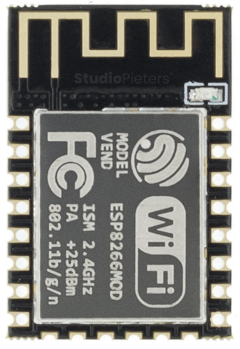
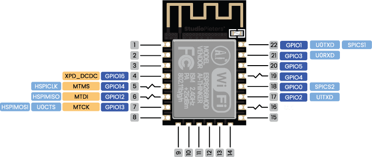
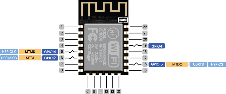
In this post, we’ll be taking a closer look at the ESP8266-12S hardware, and more specifically, the ESP8266 pinout. The ESP8266 is based on the Tensilica L106 32-bit micro controller. The ESP8266-12S pinout consists of 11 digital pins, 1 analog inputs. The versatility of the pinout provides many different options such as driving motors, LED’s, reading sensors and more. In this post, we’ll go over the capabilities of the ESP8266-12S pinout.
ESP8266 Peripherals
TThe ESP8266 peripherals include:
- 17 GPIO’s
- SPI
- I2C (implemented on software)
- I2S interfaces with DMA
- UART
- 10-bit ADC
The ADC (Analog to Digital Converter) and DAC (Digital to Analog Converter) features are assigned to specific static pins. However, you can decide which pins are UART, I2C, SPI, PWM, etc – you just need to assign them in the code. This is possible due to the ESP8266 chip’s multiplexing feature.

Power Supply
As the operating voltage range of ESP8266 is 3V to 3.6V, the board comes with a LDO voltage regulator to keep the voltage steady at 3.3V. It can reliably supply up to 600mA, which should be more than enough when ESP8266 pulls as much as 80mA during RF transmissions. The output of the regulator is also broken out to one of the sides of the board and labeled as 3V3. This pin can be used to supply power to external components.
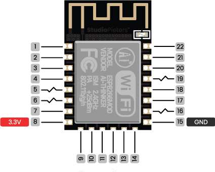
The GND pins are used to close the electrical circuit and provide a common logic reference level throughout your circuit. Always make sure that all GNDs (of the Arduino, peripherals and components) are connected to one another and have a common ground.
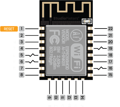
RST Pin
When the RST pin is pulled LOW, the ESP8266 resets. This is the same as pressing the on-board RESET button.
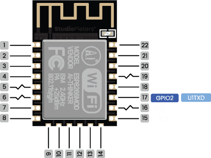
On-board LED
Most of the ESP8266 development boards have a built-in LED. This LED is usually connected to GPIO2. The LED is connected to a pull-down resistor, so when you send a HIGH signal the LED turns off.
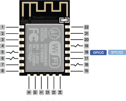
GPIO0
When GPIO0 is pulled LOW, it sets the ESP8266 into bootloader mode. This is the same as pressing the on-board FLASH/BOOT button.
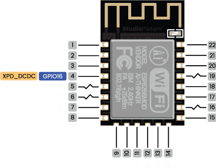
GPIO16
GPIO16 can be used to wake up the ESP8266 from deep sleep. To wake up the ESP8266 from deep sleep, GPIO16 should be connected to the RST pin.
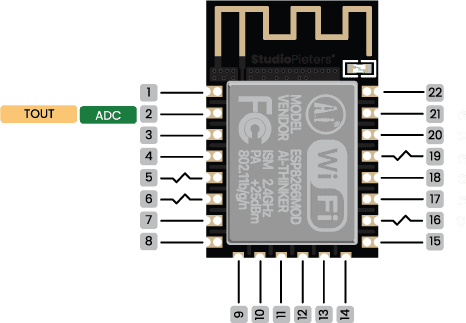
Analog
The ESP8266 only supports analog reading in one GPIO. That GPIO is called ADC0 and it is usually marked on the silkscreen as A0. The maximum input voltage of the ADC0 pin is 0 to 1V if you’re using the ESP8266 bare chip. If you’re using a development board like the ESP8266 12-F NodeMCU kit, the voltage input range is 0 to 3.3V because these boards contain an internal voltage divider.
Analog to Digital Conversion
ADC stands for Analog to Digital Converter. ADC is an electronic circuit used to convert analog signals into digital signals. This digital representation of analog signals allows the processor (which is a digital device) to measure the analog signal and use it through its operation. The ESP8266 only supports analog reading in one GPIO. That GPIO is called ADC0 and it is usually marked on the silkscreen as A0. The maximum input voltage of the ADC0 pin is 0 to 1V if you’re using the ESP8266 bare chip. If you’re using a development board like the ESP8266 12-F NodeMCU kit, the voltage input range is 0 to 3.3V because these boards contain an internal voltage divider.
Digital Pins
D0-D5, 12-14 and 16 of the ESP8266 serve as digital input/output pins.
Note: Each pin can provide up to 12 mA max. But the recommended current is 10 mA. The absolute max current provided (or sank) from all pins together is 160mA.
Digital
Digital is a way of representing voltage in 1 bit: either 0 or 1. Digital pins on the ESP8266 are pins designed to be configured as inputs or outputs according to the needs of the user. Digital pins are either on or off. When ON they are in a HIGH voltage state of 3.3V and when OFF they are in a LOW voltage state of 0V. When the digital pins are configured as output, they are set to 0 or 3.3 volts.
Between 0-3.3 volts which is converted into digital representation (0 or 1). To determine this, there are 2 thresholds: Below 0.8v – considered as 0. Above 2v – considered as 1. When connecting a component to a digital pin, make sure that the logic levels match. If the voltage is in between the thresholds, the returning value will be undefined.
PWM
In general, Pulse Width Modulation (PWM) is a modulation technique used to encode a message into a pulsing signal. A PWM is comprised of two key components: frequency and duty cycle. The PWM frequency dictates how long it takes to complete a single cycle (period) and how quickly the signal fluctuates from high to low. The duty cycle determines how long a signal stays high out of the total period. Duty cycle is represented in percentage.
On the ESP8266, the PWM enabled pins produce a constant frequency of ~ 500Hz, while the duty cycle changes according to the parameters set by the user. See the following illustration:
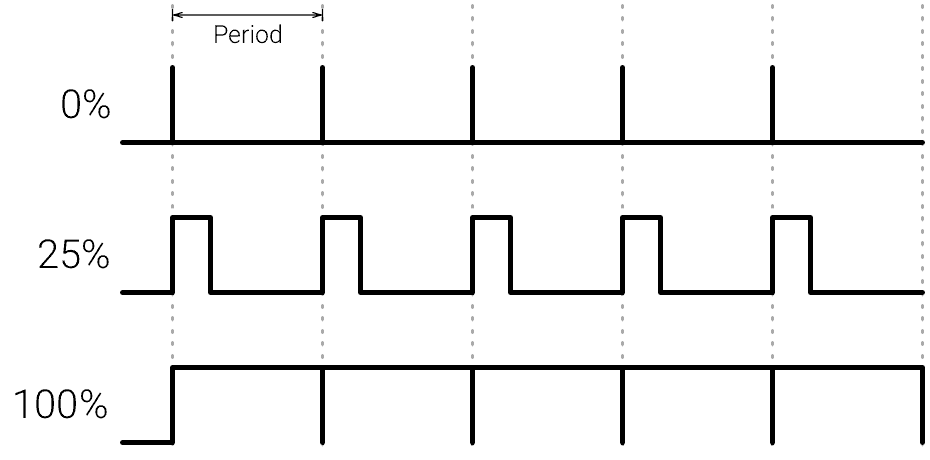
PWM signals are used for speed control of DC motors, dimming LEDs and more. ESP8266 allows software PWM in all I/O pins: GPIO0 to GPIO16. PWM signals on ESP8266 have 10-bit resolution. To set a PWM signal, you need to define these parameters in the code:
- Signal’s frequency;
- Duty cycle;
- PWM channel;
- GPIO where you want to output the signal.
Serial Communication
Serial communication is used to exchange data between the Arduino board and another serial device such as computers, displays, sensors and more. Each Arduino board has at least one serial port. Serial communication occurs on digital pins 0 (RX) and 1 (TX) as well as via USB. Arduino supports serial communication through digital pins with the SoftwareSerial Library as well. This allows the user to connect multiple serial-enabled devices and leave the main serial port available for the USB.
Software serial and hardware serial – Most microcontrollers have hardware designed to communicate with other serial devices. Software serial ports use a pin-change interrupt system to communicate. There is a built-in library for Software Serial communication. Software serial is used by the processor to simulate extra serial ports. The only drawback with software serial is that it requires more processing and cannot support the same high speeds as hardware serial.
SPI
SPI –SS/SCK/MISO/MOSI pins are the dedicated pins for SPI communication. Serial Peripheral Interface (SPI) is a serial data protocol used by microcontrollers to communicate with one or more external devices in a bus like connection. The SPI can also be used to connect 2 microcontrollers. On the SPI bus, there is always one device that is denoted as a Master device and all the rest as Slaves. In most cases, the microcontroller is the Master device. The SS (Slave Select) pin determines which device the Master is currently communicating with. SS/SCK/MISO/MOSI pins are the dedicated pins for SPI communication. SPI enabled devices always have the following pins:
MISO (Master In Slave Out) – A line for sending data to the Master device
MOSI (Master Out Slave In) – The Master line for sending data to peripheral devices
SCK (Serial Clock) – A clock signal generated by the Master device to synchronize data transmission.
SS (Slave Select) pin determines which device the Master is.
By default, the pin mapping for SPI is:
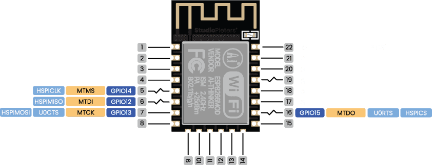
- GPIO12: MISO
- GPIO13: MOSI
- GPIO14: SCLK
- GPIO15: CS
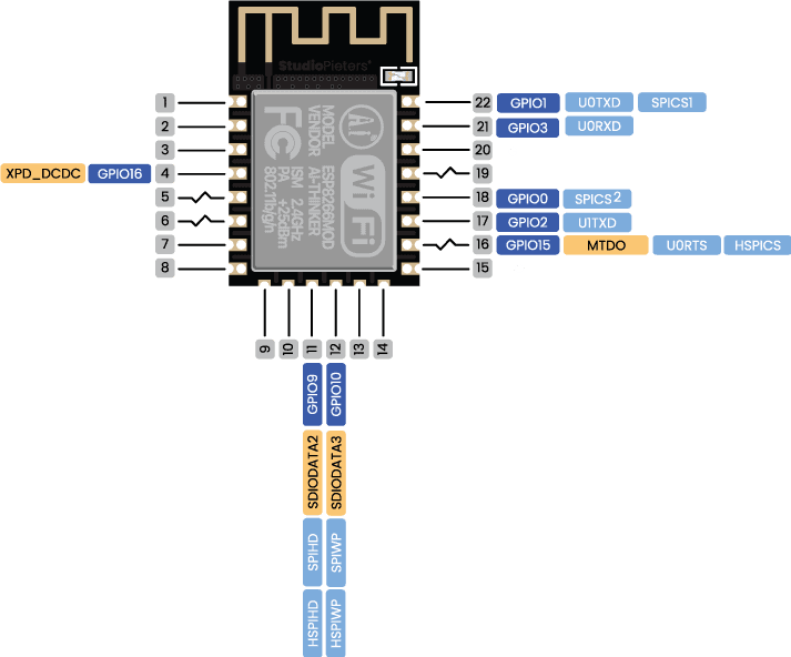
SPI flash integrated
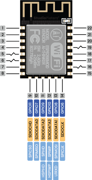
GPIO 6 to GPIO 11 are exposed in some ESP8266 development boards. However, these pins are connected to the integrated SPI flash on the ESP8266 chip and are not recommended for other uses. So, don’t use these pins in your projects!
- GPIO 6 (SCK/CLK)
- GPIO 7 (SDO/SD0)
- GPIO 8 (SDI/SD1)
- GPIO 9 (SHD/SD2)
- GPIO 10 (SWP/SD3)
- GPIO 11 (CSC/CMD)
I2C
I2C is a communication protocol commonly referred to as the “I2C bus”. The I2C protocol was designed to enable communication between components on a single circuit board. With I2C there are 2 wires referred to as SCL and SDA. SCL/SDA pins are the dedicated pins for I2C communication.
SCL is the clock line which is designed to synchronize data transfers.
SDA is the line used to transmit data.
Each device on the I2C bus has a unique address, up to 255 devices can be connected on the same bus. The ESP8266 has two I2C channels and any pin can be set as SDA or SCL. The default I2C pins are.
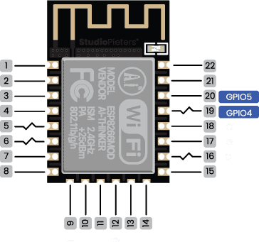
- GPIO5: SCL
- GPIO4: SDA
Interrupt
An external interrupt is a system interrupt that occurs when outside interference is present. Interference can come from the user or other hardware devices in the network. Common uses for these interrupts in ESP8266 are reading the frequency a square wave generated by encoders or waking up the processor upon an external event. on the ESP8266, The ESP8266 supports interrupts in any GPIO, except GPIO16.

Strapping Pins
The ESP8266 chip has the following strapping pins:
- GPIO16: pin is high at BOOT
- GPIO0: boot failure if pulled LOW
- GPIO2: pin is high on BOOT, boot failure if pulled LOW
- GPIO15: boot failure if pulled HIGH
- GPIO3: pin is high at BOOT
- GPIO1: pin is high at BOOT, boot failure if pulled LOW
- GPIO10: pin is high at BOOT
- GPIO9: pin is high at BOOT
These are used to put the ESP8266 into bootloader or flashing mode. On most development boards with built-in USB/Serial, you don’t need to worry about the state of these pins. The board puts the pins in the right state for flashing or boot mode.
However, if you have peripherals connected to those pins, you may have trouble trying to upload new code, flashing the ESP8266 with new firmware or resetting the board. If you have some peripherals connected to the strapping pins and you are getting trouble uploading code or flashing the ESP8266, it may be because those peripherals are preventing the ESP8266 to enter the right mode. After resetting, flashing, or booting, those pins work as expected.
Pins HIGH at Boot
Some GPIO’s change its state to HIGH or output PWM signals at boot or reset. This means that if you have outputs connected to these GPIOs you may get unexpected results when the ESP8266 resets or boots.
- GPIO16
- GPIO3
- GPIO1
- GPIO10
- GPIO9

Additionally, the other GPIO’s, except GPIO5 and GPIO4, can output a low-voltage signal at boot, which can be problematic if these are connected to transistors or relays! GPIO4 and GPIO5 are the most safe to use GPIO’s if you want to operate relays!
GPIO current drawn
The absolute maximum current drawn per GPIO is 12 mA according to the “Recommended Operating Conditions” section in the ESP8266 datasheet.
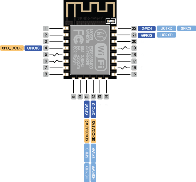
Best Pins to Use – ESP8266
One important thing to notice about ESP8266 is that the GPIO number doesn’t match the label on the board silkscreen. For example, D0 corresponds to GPIO16 and D1 corresponds to GPIO5. The following table shows the correspondence between the labels on the silkscreen and the GPIO number as well as what pins are the best to use in your projects, and which ones you need to be cautious.

The pins highlighted in green are OK to use. The ones highlighted in yellow are OK to use, but you need to pay attention because they may have unexpected behaviour mainly at boot. The pins highlighted in red are not recommended to use as inputs or outputs.
| Label | GPIO | Input | Output | Notes |
| D0 | GPIO16 | no interrupt | no PWM or I2C support | HIGH at boot used to wake up from deep sleep |
| D1 | GPIO5 | OK | OK | often used as SCL (I2C) |
| D2 | GPIO4 | OK | OK | often used as SDA (I2C) |
| D3 | GPIO0 | pulled up | OK | connected to FLASH button, boot fails if pulled LOW |
| D4 | GPIO2 | pulled up | OK | HIGH at boot connected to on-board LED, boot fails if pulled LOW |
| D5 | GPIO14 | OK | OK | SPI (SCLK) |
| D6 | GPIO12 | OK | OK | SPI (MISO) |
| D7 | GPIO13 | OK | OK | SPI (MOSI) |
| D8 | GPIO15 | pulled to GND | OK | SPI (CS) Boot fails if pulled HIGH |
| RX | GPIO3 | OK | RX pin | HIGH at boot |
| TX | GPIO1 | TX pin | OK | HIGH at boot debug output at boot, boot fails if pulled LOW |
| A0 | ADC0 | Analog input | X |
Continue reading for a more detailed and in-depth analysis of the ESP8266 GPIO’s and its functions.
Overview
The ESP8266 Microcontroller is one of the most versatile boards on the market today and that’s why we decided to focus on it in this guide. This guide displays most of its capabilities, but there are also more advanced options which we did not go into in this post.
The important thing to know when you choose a board for your project is its capabilities and limitations. It’s also important to understand the different communication protocols that the board uses. Of course, you don’t need to remember all of this information, you can always go back to this post and read the relevant information for you (this is a good time to bookmark this Blog btw).
Download
Download the ESP8266 Reference sheet for free!

Reference:
Espressif, Technical specifications for the ESP32, https://www.espressif.com/sites/default/files/documentation/esp32_technical_reference_manual_en.pdf Espressif , Technical specifications for the ESP32, https://www.espressif.com/sites/default/files/documentation/esp32_datasheet_en.pdf RandomNerdTutorials, ESP32 Pinout Reference,Which GPIO pins should you use, https://randomnerdtutorials.com/esp32-pinout-reference-gpios