ESP32-C3 is a single-core Wi-Fi and Bluetooth 5 (LE) microcontroller SoC, based on the open-source RISC-V architecture. It strikes the right balance of power, I/O capabilities and security, thus offering the optimal cost-effective solution for connected devices. The availability of Wi-Fi and Bluetooth 5 (LE) connectivity not only makes the device’s configuration easy, but it also facilitates a variety of use-cases based on dual connectivity. Not all pins are exposed in all ESP32-C3 development boards, and there are some pins that cannot be used. There are many questions on how to use the ESP32-C3 GPIO’s. What pins should you use? What pins should you avoid using in your projects? This blog is a simple and easy to follow reference guide for the ESP32-C3 GPIO’s.
Note: this blog contains all information available so far, regarding the ESP32-C3. If any information is still missing or incorrect, please let me know, and I will adjust it as soon as possible.

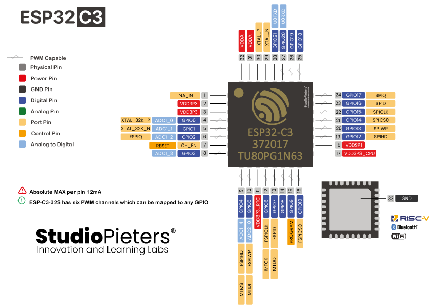
ESP32-C3 CHIP PINOUT
The following figure illustrates the original Espressif ESP32-C3 QFN 5×5 chip pinout. Use this diagram if you’re using an ESP32 bare chip in your projects. On the bottom of this blog, you can download the PDF with the ESP32-C3 QFN 5×5 chip – PinOut!
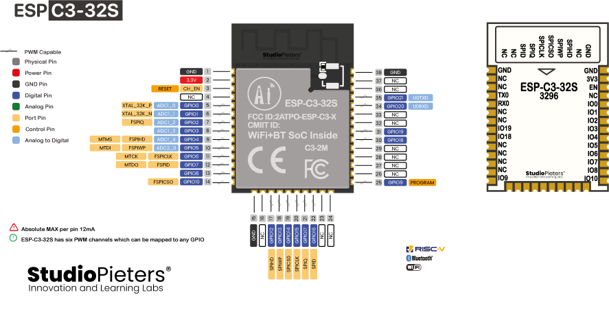
ESP-C3-32S Module PINOUT
The following figure illustrates the Ai-Thinker ESP-C3-32S Module pinout. Use this diagram if you’re using an Ai-Thinker ESP-C3-32S bare module in your projects. On the bottom of this blog, you can download the PDF with the Ai-Thinker ESP-C3-32S Module – PinOut!
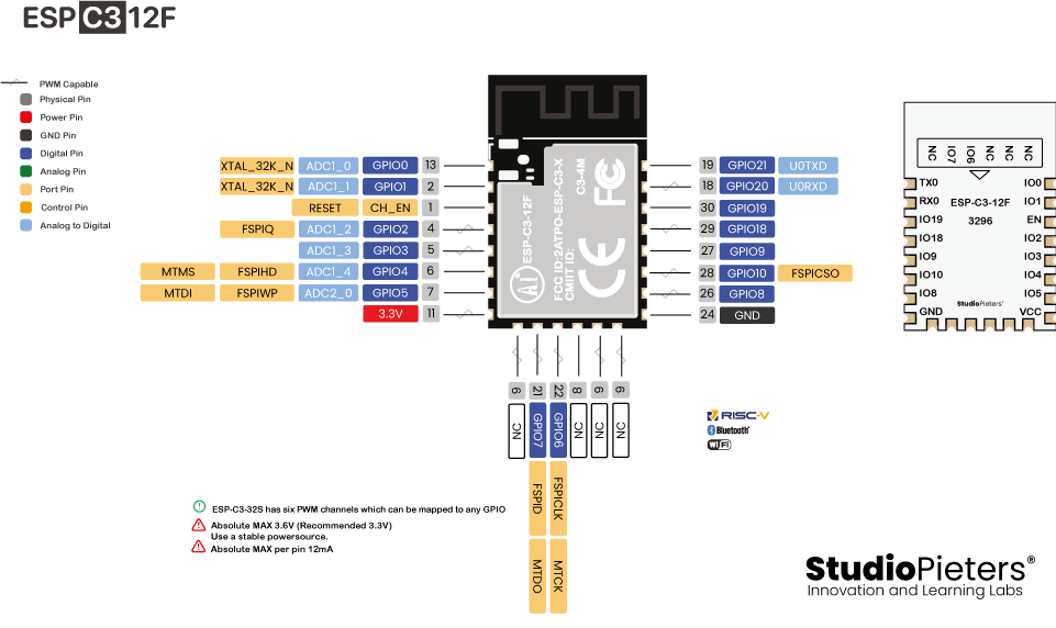
ESP-C3-12F Module PINOUT
The following figure illustrates the Ai-Thinker ESP-C3-12F Module pinout. Use this diagram if you’re using an Ai-Thinker ESP-C3-12F bare module in your projects. On the bottom of this blog you can download the PDF with the Ai-Thinker ESP-C3-12F Module – PinOut!
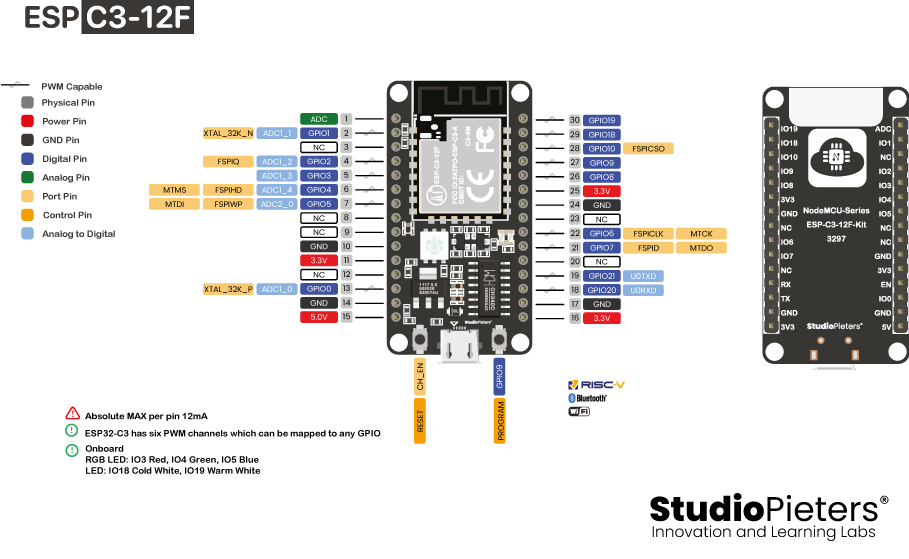
ESP-C3-12F Development Board PINOUT
If you’re using an Ai-Thinker ESP-C3-12F Development board, you can use the following GPIO diagram as a reference. ESP32 30 pin Development board pinout diagram GPIO’s pins. On the bottom of this blog, you can download the PDF with the Ai-Thinker ESP-C3-12F Development Board – PinOut!
Note: At the moment, there are a wide variety of Modules and development boards with the ESP32-C3 chip that differ in the number of accessible GPIO’s, size, form factor, etc…
ESP32-C3 Peripherals
The ESP32-C3 peripherals include:
- 22 programmable GPIO’s
- 3 SPI interfaces
- 2 UART interfaces
- 1 I2C interfaces
- LED PWM controller, with up to 6 channels
- 1 temperature sensor
The ADC (Analogue to Digital Converter) and DAC (Digital to Analogue Converter) features are assigned to specific static pins. However, you can decide which pins are UART, I2C, SPI, PWM, etc – you just need to assign them in the code. This is possible due to the ESP32-C3 chip’s multiplexing feature.
BEST PINS TO USE – ESP32-C3
Additionally, there are pins with specific features that make them suitable or not for a specific project. The following table shows what pins are best to use as inputs, outputs and which ones you need to be cautious.

The pins highlighted in Green are OK to use. The ones highlighted in Yellow are OK to use, but you need to pay attention because they may have unexpected behaviour, mainly at boot. The pins highlighted in Red are not recommended to use as inputs or outputs.
| GPIO | Input | Output | Notes |
| 0 | OK | OK | |
| 1 | OK | OK | |
| 2 | OK | OK | |
| 3 | OK | OK | |
| 4 | OK | OK | |
| 5 | OK | OK | |
| 6 | OK | OK | |
| 7 | OK | OK | |
| 8 | OK | OK | |
| 9 | OK | OK | |
| 10 | OK | OK | |
| 11 | X | X | connected to the integrated SPI flash |
| 12 | X | X | connected to the integrated SPI flash |
| 13 | X | X | connected to the integrated SPI flash |
| 14 | X | X | connected to the integrated SPI flash |
| 15 | X | X | connected to the integrated SPI flash |
| 16 | X | X | connected to the integrated SPI flash |
| 17 | X | X | connected to the integrated SPI flash |
| 18 | X | OK | |
| 19 | X | OK | |
| 20 | U0RXD | OK | |
| 21 | OK | U0TXD |
SPI flash integrated on the ESP32-C3
GPIO 11 – GPIO 17 are exposed in some ESP32-C3 development boards. However, these pins are connected to the integrated SPI flash and are not recommended for other uses. So, don’t use these pins in your projects!
- GPIO 11 (Output power supply for flash)
- GPIO 12 (SPIHD)
- GPIO 13 (SPIWP)
- GPIO 14 (SPICS0)
- GPIO 15 (SPICLK)
- GPIO 16 SPID)
- GPIO 17 (SPIQ)

Analogue to Digital Converter (ADC)
The ESP32-C3 has 2 × 12-bit SAR ADC’s, up to 6 channels (while the ESP8266 only has 1x 10 bits ADC). These are the GPIO’s that can be used as ADC and respective channels.
- ADC1_CH0 (GPIO 0)
- ADC1_CH1 (GPIO 1)
- ADC1_CH2 (GPIO 2)
- ADC1_CH3 (GPIO 3)
- ADC1_CH4 (GPIO 4)
- ADC2_CH0 (GPIO 5)
ESP32-C3 integrates two 12-bit SAR ADCs.
• ADC1 supports measurements on 5 channels, and is factory-calibrated.
• ADC2 supports measurements on 1 channel, and is not factory-calibrated.
ESP32-C3 has 22 GPIO pins which can be assigned various functions by configuring corresponding registers. Besides digital signals, some GPIO’s can also be used for analogue functions, such as ADC.
How to use the ESP32-C3 ADC pins
The ADC input channels have a 12 bit resolution. This means that you can get analogue readings ranging from 0 to 4095, in which 0 corresponds to 0V and 4095 to 3.3V. You also have the ability to set the resolution of your channels on the code, as well as the ADC range.

Note: The ESP32-C3 ADC pins don’t have a linear behaviour. You probably won’t be able to distinguish between 0 and 0.1V, or between 3.2 and 3.3V. You need to keep that in mind when using the ADC pins.
PWM
The LED PWM controller can generate independent digital waveform on six channels on Any GPIO pins. The LED PWM controller:
- Can generate digital waveform with configurable periods and duty cycle. The accuracy of duty cycle can be up to 18 bits.
- Has multiple clock sources, including APB clock and external main crystal clock.
- Can operate when the CPU is in Light-sleep mode.
- Supports gradual increase or decrease of duty cycle, which is useful for the LED RGB colour gradient generator.
I2C
ESP32-C3 family has an I2C bus interface which is used for I2C master mode or slave mode, depending on the user’s configuration. The I2C interface supports:
• Standard mode (100 Kbit/s)
• Fast mode (400 Kbit/s)
• Up to 800 Kbit/s (constrained by SCL and SDA pull-up strength)
• 7-bit and 10-bit addressing mode
• Double addressing mode
• 7-bit broadcast address
Users can configure instruction registers to control the I2C interface for more flexibility. ESP32-C3 has only one I2C controller (also referred to as port) which is responsible for handling communications on I2C bus. The I2C controller can operate as master or slave.
The ESP32 has one I2C channels and any GPIO pin can be set as SDA or SCL.
SPI
ESP32-C3 features three SPI interfaces (SPI0, SPI1, and SPI2). SPI0 and SPI1 can only be configured to operate in SPI memory mode, while SPI2 can be configured to operate in both SPI memory and general-purpose SPI modes. By default, the pin mapping for SPI is:
| SPI | MOSI a.k.a D | MISO a.k.a Q | CLK | CS |
| VSPI | GPIO 16 | GPIO 17 | GPIO 15 | GPIO 14 |
The SPI2 channels can be set to any GPIO pin
Interrupts
All GPIO’s can be configured as interrupts.
Strapping Pins
The ESP32-C3 chip has the following strapping pins:
- GPIO 2
- GPIO 8
- GPIO 9
These are used to put the ESP32-C3 into bootloader or flashing mode. On most development boards with built-in USB/Serial, you don’t need to worry about the state of these pins. The board puts the pins in the right state for flashing or boot mode.
However, if you have peripherals connected to those pins, you may have trouble trying to upload new code, flashing the ESP32-C3 with new firmware or resetting the board. If you have some peripherals connected to the strapping pins, and you are getting trouble uploading code or flashing the ESP32-C3, it may be because those peripherals are preventing the ESP32-C3 to enter the right mode. After resetting, flashing, or booting, those pins work as expected.
Pins HIGH at Boot
Some GPIO’s change its state to HIGH or output PWM signals at boot or reset. This means that if you have outputs connected to these GPIO’s you may get unexpected results when the ESP32-C3 resets or boots.
- GPIO 0 – GPIO 8
- GPIO 10
- GPIO 11
- GPIO 18
- GPIO 19 (input disabled, pull-up resistor enabled)

Enable (EN)
Enable (EN) is the 3.3V regulator’s enable pin. It’s pulled up, so connect to ground to disable the 3.3V regulator. This means that you can use this pin connected to a push button to restart your ESP32-C3, for example.
High: on, enables the chip.
Low: off, the chip powers off.
Note: Do not leave the CHIP_EN pin floating.
GPIO current drawn
The absolute maximum current drawn per GPIO is 40mA according to the “Recommended Operating Conditions” section in the ESP32-C3 datasheet.
ESP32-C3 Temperature Sensor
The ESP32-C3 also features a built-in temperature sensor. The temperature sensor generates a voltage that varies with temperature. The voltage is internally converted via an ADC into a digital value. The temperature sensor has a range of –40 °C to 125 °C. It is designed primarily to sense the temperature changes inside the chip. The temperature value depends on factors like microcontroller clock frequency or I/O load. Generally, the chip’s internal temperature is higher than the operating ambient temperature.

DOWNLOADS
Download your Pinout sheet here.
Reference:
Espressif, Datasheet, https://www.espressif.com/sites/default/files/documentation/esp32-c3_datasheet_en.pdf ai-thinker, ESP-C3-12F Specification, https://docs.ai-thinker.com/_media/esp32/docs/esp-c3-12f_specification.pdf cnx-software, AI-Thinker introduces 5 ESP32-C3 modules pin compatible with ESP8266 & ESP32 modules, https://www.cnx-software.com/2021/04/24/ai-thinker-esp32-c3-modules-compatible-esp8266-esp32 elektormagazine, Aan de slag met de ESP32-C3 RISC-V MCU, https://www.elektormagazine.nl/news/aan-de-slag-met-de-esp32-c3-risc-v-mcu