For those that starting with the Node MCU ESP modules, I have made some pinout diagrams, their functions and how to use them. The Node MCU ESP8266 12-E chip comes with 30 GPIO pins. All GPIO’s are exposed on all ESP8266 development boards, some GPIO’s are not recommended to use, and others have very specific functions. With this guide, you’ll learn how to properly use the ESP8266 GPIO’s and avoid hours of frustration by using the most suitable pins for your projects.

ESP8266 12-E Chip Pinout
The following figure illustrates the ESP8266 12-E chip pinout. Use this diagram if you’re using an ESP8266 bare chip in your projects. On the bottom of this blog you can download the PDF!
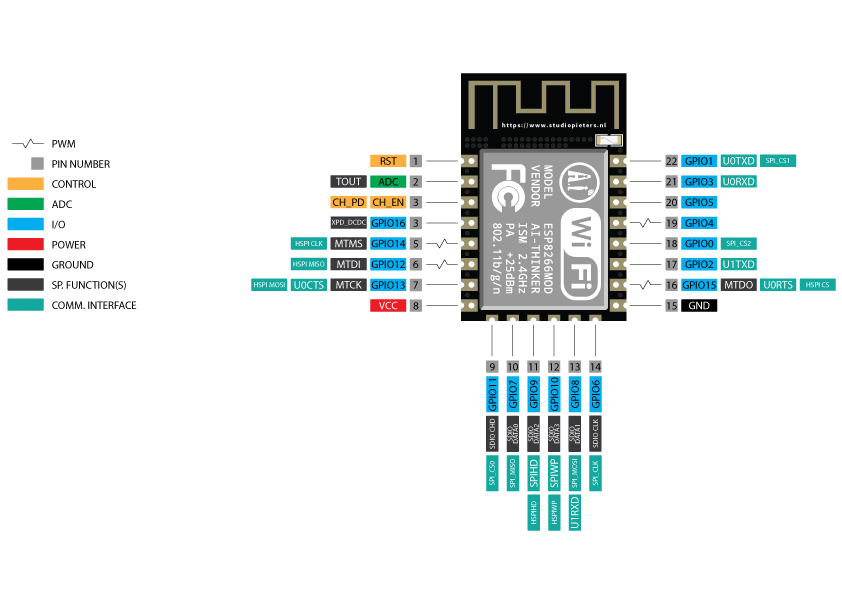
Note: not all GPIO’s are accessible in all development boards, but each specific GPIO works in the same way regardless of the development board you’re using. If you’re just getting started with the ESP8266, we recommend reading our blog: Getting Started with the ESP8266.
At the moment, there are a wide variety of development boards with the ESP8266 chip that differ in the number of accessible GPIO’s, size, form factor, etc…
ESP8266 NodeMCU Pinout
If you’re using an ESP8266-LoLin board, you can use the following GPIO diagram as a reference. On the bottom of this blog, you can download the PDF!
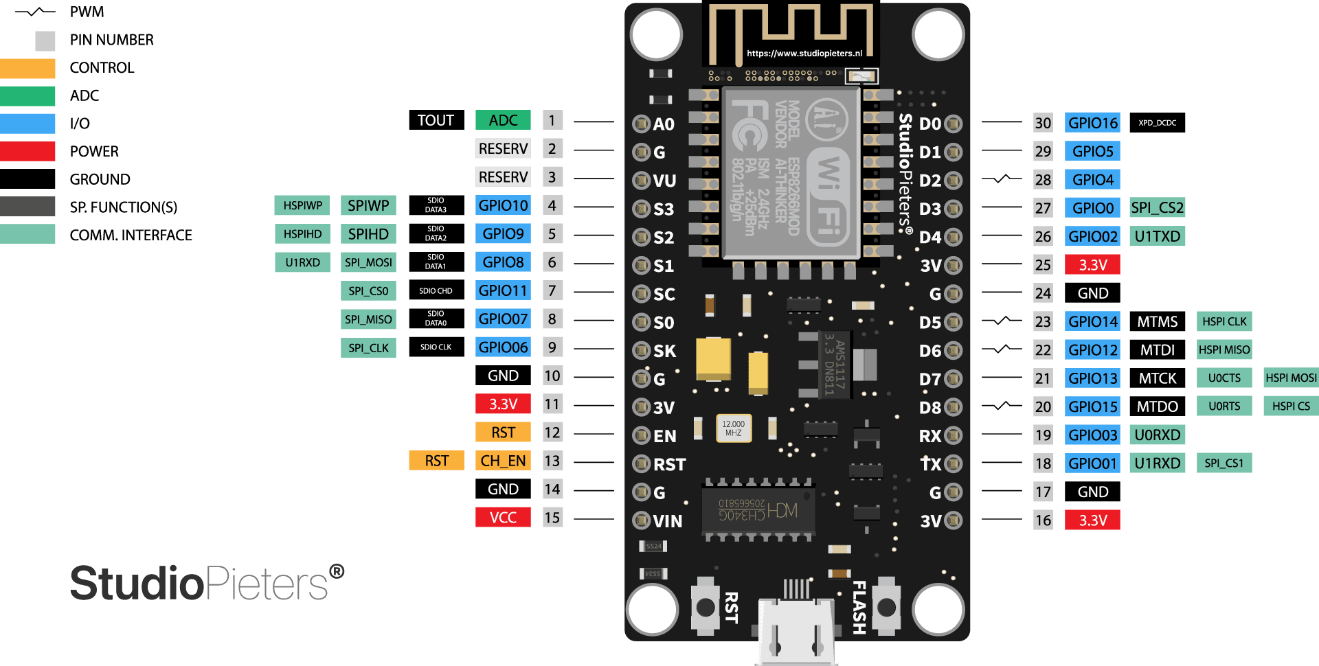
ESP8266 NodeMCU Pinout Peripherals
The ESP8266 Node MCU Pinout peripherals include:
- 17 GPIO’s
- SPI
- I2C (implemented in software)
- I2S interfaces with DMA
- UART
- 10-bit ADC
Best Pins to Use – ESP8266 NodeMCU
One important thing to notice about ESP8266 Node MCU is that the GPIO number doesn’t match the label on the board silkscreen. For example, D0 corresponds to GPIO16 and D1 corresponds to GPIO5. The following table shows the correspondence between the labels on the silkscreen and the GPIO number, as well as what pins are the best to use in your projects, and which ones you need to be cautious.

The pins highlighted in green are OK to use. The ones highlighted in yellow are OK to use, but you need to pay attention because they may have unexpected behaviour, mainly at boot. The pins highlighted in red are not recommended to use as inputs or outputs.
| Label | GPIO | Input | Output | Notes |
| D0 | GPIO16 | no interrupt | no PWM or I2C support | HIGH at boot used to wake up from deep sleep |
| D1 | GPIO5 | OK | OK | often used as SCL (I2C) |
| D2 | GPIO4 | OK | OK | often used as SDA (I2C) |
| D3 | GPIO0 | pulled up | OK | connected to FLASH button, boot fails if pulled LOW |
| D4 | GPIO2 | pulled up | OK | HIGH at boot connected to on-board LED, boot fails if pulled LOW |
| D5 | GPIO14 | OK | OK | SPI (SCLK) |
| D6 | GPIO12 | OK | OK | SPI (MISO) |
| D7 | GPIO13 | OK | OK | SPI (MOSI) |
| D8 | GPIO15 | pulled to GND | OK | SPI (CS) Boot fails if pulled HIGH |
| RX | GPIO3 | OK | RX pin | HIGH at boot |
| TX | GPIO1 | TX pin | OK | HIGH at boot debug output at boot, boot fails if pulled LOW |
| A0 | ADC0 | Analog Input | X |
Continue reading for a more detailed and in-depth analysis of the ESP8266 Node MCU GPIO’s and its functions.
GPIO’s connected to the Flash Chip
GPIO6 to GPIO11 are usually connected to the flash chip in ESP8266 boards. So, these pins are not recommended to use.
Pins used during Boot
The ESP8266 Node MCU can be prevented from booting if some pins are pulled LOW or HIGH. The following list shows the state of the following pins on BOOT:
- GPIO16: pin is high at BOOT
- GPIO0: boot failure if pulled LOW
- GPIO2: pin is high on BOOT, boot failure if pulled LOW
- GPIO15: boot failure if pulled HIGH
- GPIO3: pin is high at BOOT
- GPIO1: pin is high at BOOT, boot failure if pulled LOW
- GPIO10: pin is high at BOOT
- GPIO9: pin is high at BOOT
Pins HIGH at Boot
There are certain pins that output a 3.3V signal when the ESP8266 Node MCU boots. This may be problematic if you have relays or other peripherals connected to those GPIO’s. The following GPIO’s output a HIGH signal on boot:
- GPIO16
- GPIO3
- GPIO1
- GPIO10
- GPIO9
Additionally, the other GPIO’s, except GPIO5 and GPIO4, can output a low-voltage signal at boot, which can be problematic if these are connected to transistors or relays! GPIO4 and GPIO5 are the safest to use GPIO’s if you want to operate relays!

Analog Input
The ESP8266 Node MCU only supports analogue reading in one GPIO. That GPIO is called ADC0, and it is usually marked on the silkscreen as A0. The maximum input voltage of the ADC0 pin is 0 to 1V if you’re using the ESP8266 bare chip. If you’re using a development board like the ESP8266 12-E Node MCU kit, the voltage input range is 0 to 3.3V because these boards contain an internal voltage divider.
On-board LED
Most of the ESP8266 development boards have a built-in LED. This LED is usually connected to GPIO2. The LED is connected to a pull-down resistor, so when you send a HIGH signal, the LED turns off.
RST Pin
When the RST pin is pulled LOW, the ESP8266 resets. This is the same as pressing the on-board RESET button.
GPIO0
When GPIO0 is pulled LOW, it sets the ESP8266 into bootloader mode. This is the same as pressing the on-board FLASH/BOOT button.
GPIO16
GPIO16 can be used to wake up the ESP8266 from deep sleep. To wake up the ESP8266 from deep sleep, GPIO16 should be connected to the RST pin.
I2C
The ESP8266 doesn’t have hardware I2C pins, but it can be implemented in software. So you can use any GPIO’s as I2C. Usually, the following GPIO’s are used as I2C pins:
- GPIO5: SCL
- GPIO4: SDA
SPI
The pins used as SPI in the ESP8266 are:
- GPIO12: MISO
- GPIO13: MOSI
- GPIO14: SCLK
- GPIO15: CS
PWM Pins
ESP8266 allows software PWM in all I/O pins: GPIO0 to GPIO16. PWM signals on ESP8266 have 10-bit resolution.
Interrupt Pins
The ESP8266 supports interrupts in any GPIO, except GPIO16.

Downloads
Download your Pinout sheet here.