This is one of my bucket list the CNC – Mini Laser Engraver. You probably have seen one come by at one point. This is an blog on how I made an Arduino CNC – Mini Laser Engraver for wood and Thin paper, Just using some old DVD drive stepper mechanism and a 250mW laser.

CNC – Mini Laser Engraver
Home and office laser engraving have become so much easier these days. Once strictly used by industrial manufacturers, laser engraving is increasingly adopted by small businesses, product designers, makers, and even hobbyists. In some cases, a laser engraver might prove to be the most advantageous manufacturing technology for your specific application. Before pulling out your wallet, we have also compiled everything you need to know about laser engravers into a comprehensive guide to get you started in this great technology.
How does Laser Engraving work
The high heat of the laser beam vaporises the material, thereby cutting into the part’s surface and physically removing material. This process leaves a cavity in the surfaces that is not only visible with high contrast but also noticeable by touch. There are noteworthy differences in the depth of this cavity that varies between 0.02″ in metals to 0.125″ in softer materials.
Usually, the engraved areas become black. Multi-layer materials offer an alternative, as they enable them to engrave other colours than black. By removing the top layers, the lower layers become visible.

Another variant of laser engraving is relief engraving. The laser creates a deep engraving with distinct heights. This variant is beyond any doubt the most impressive since the overall effect is that of a wooden sculpture. If you want to create a relief engraving, you need a gray scale design and set your laser to translate the different values into different heights.
Safety First
Even the first laser was recognised as being potentially dangerous. Theodore Maiman characterised the first laser as having a power of one “Gillette” as it could burn through one Gillette razor blade. Today, it is accepted that even low-power lasers with only a few milliwatts of output power can be hazardous to human eyesight when the beam hits the eye directly or after reflection from a shiny surface. At wavelengths which the cornea and the lens can focus well, the coherence and low divergence of laser light means that it can be focused by the eye into an extremely small spot on the retina, resulting in localised burning and permanent damage in seconds or even less time.
Lasers are usually labelled with a safety class number, which identifies how dangerous the laser is:
- Class 1 is inherently safe, usually because the light is contained in an enclosure, for example in CD players.
- Class 2 is safe during normal use; the blink reflex of the eye will prevent damage. Usually up to 1 mW power, for example laser pointers.
- Class 3R (formerly IIIa) lasers are usually up to 5 mW and involve a small risk of eye damage within the time of the blink reflex. Staring into such a beam for several seconds is likely to cause damage to a spot on the retina.
- Class 3B can cause immediate eye damage upon exposure.
- Class 4 lasers can burn skin, and in some cases, even scattered light can cause eye and/or skin damage. Many industrial and scientific lasers are in this class.

The indicated powers are for visible-light, continuous-wave lasers. For pulsed lasers and invisible wavelengths, other power limits apply. People working with class 3B and class 4 lasers can protect their eyes with safety goggles which are designed to absorb light of a particular wavelength.

Infrared lasers with wavelengths longer than about 1.4 micrometers are often referred to as “eye-safe”, because the cornea tends to absorb light at these wavelengths, protecting the retina from damage. The label “eye-safe” can be misleading, however, as it applies only to relatively low power continuous wave beams; a high power or Q-switched laser at these wavelengths can burn the cornea, causing severe eye damage, and even moderate power lasers can injure the eye.
Hardware
- Arduino Nano.
- 2 x DVR8825 Stepper motor driver.
- 2 x DVD drive stepper mechanis.
- 1 x IRFZ44N N-CHANNEL MOSFET.
- 1 x LM7805 Voltage regulator (with Heat-sink).
- 1 x 47Ω resistor.
- 1 x 10kΩ resistor.
- 1 x 1000μF16V capacitor.
- 1 x 250mW Laser with adjustable lens (or above).
- 1 x 12v 2Amps power supply minimum
- 8 x small neodymium magnets
- Laser Safety Glasses!
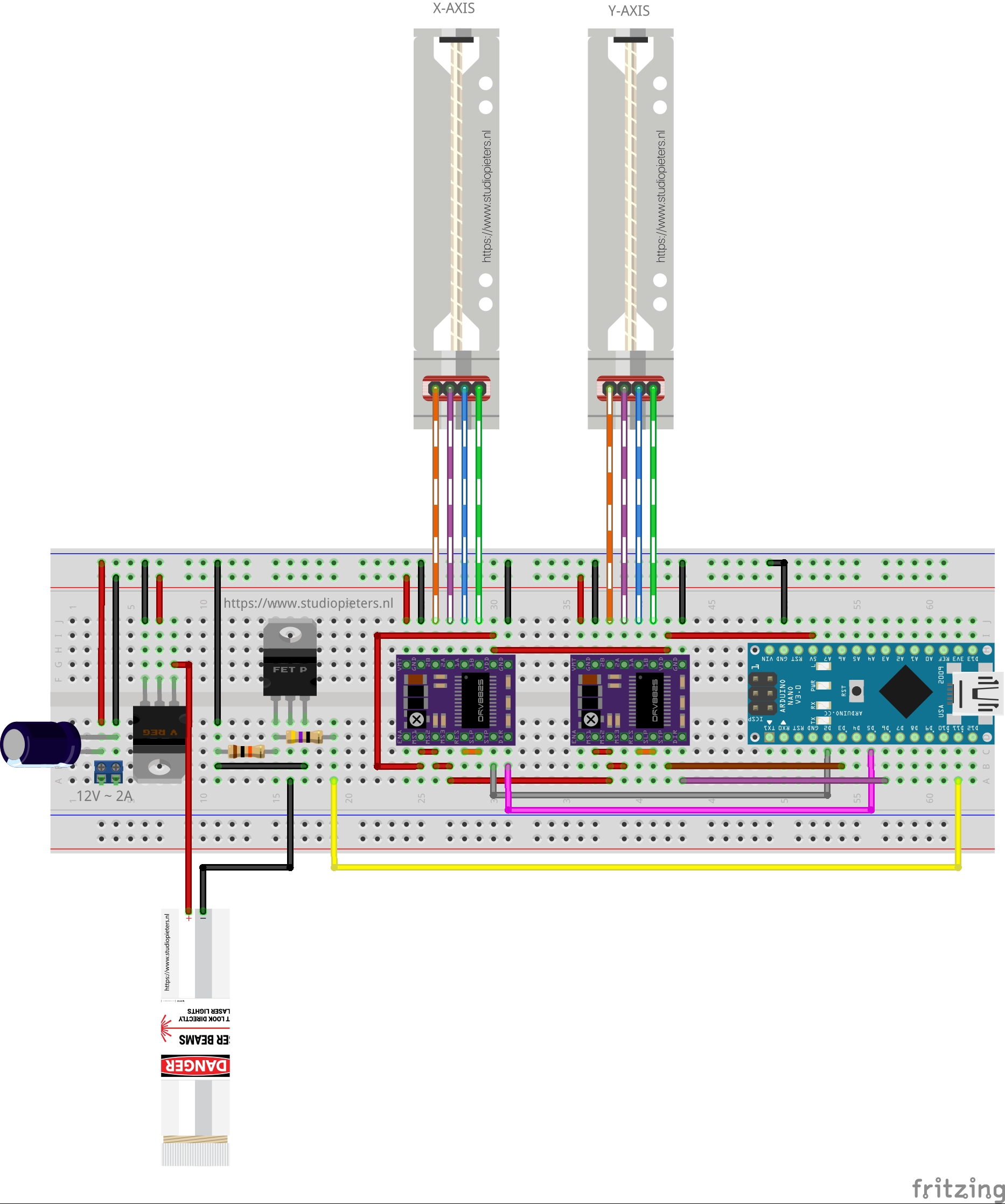
Scheme
Because i’m making a test set-up, i’m using a breadboard for the electronics. Here is my scheme.
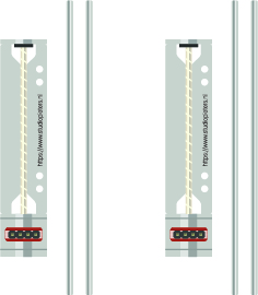
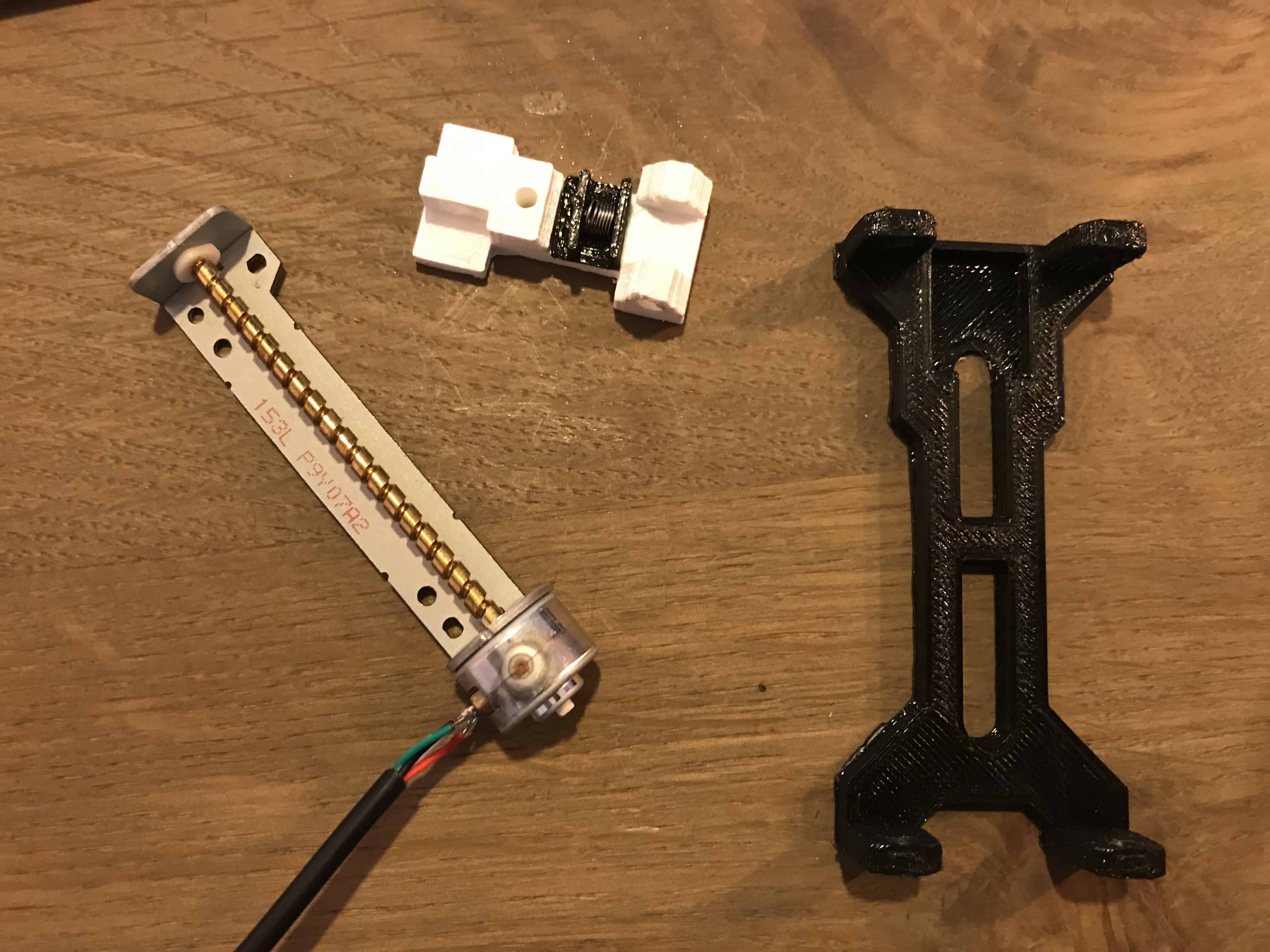
DVD Drive Stepper Mechanism
To make your CNC – Mini Laser Engraver u need two CD / DVD driver mechanism, one for the X-Axis and the second for the Y-axis. Using a small Phillips head screw driver I removed all the screws and detached stepper motor, the sliding rails and the follower. The stepper motors are 4-pin Bipolar Stepper Motor.
The small size and low cost of a DVD motor mean that you can’t expect high resolution from the motor. That is provided by the lead screw. Also, not all such motors do 20 steps/rev. 24 is also a common spec. You’ll just have to test your motor to see what it does.
Calculating the resolution of the Stepper motor
In order to measure the resolution of the CD/DVD drive stepper motor, a digital micrometer was used. The distance along the screw was measured. The total length of the screw using a micrometer, which turned out to be 51.56 mm. To determine the lead value which is the distance between two adjacent threads on the screw.
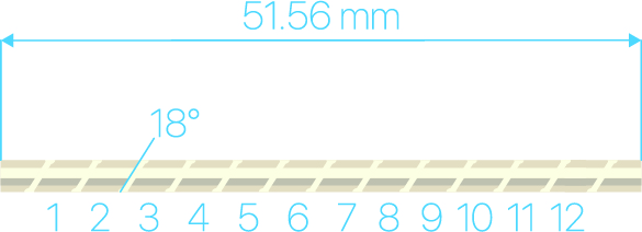
The threads were counted to be 12 threads within this distance.

Lead (distance between adjacent threads) = ( total length / number of threads)
Lead = 51.56 mm / 12 = 4.29 mm/rev.
The step angle is 18 degrees which corresponds to 20 steps/revolution (18° x 20 = 360°). Now that all the information needed is available, the resolution of the stepper motor could be calculated as shown below:
Resolution = (Distance between adjacent threads) / (N Steps/rev) = (4.29 mm/rev) / ( 20 steps/rev) = 0.214 mm/step.
Which is 3 times better the resolution required which is 0.68mm / Step.
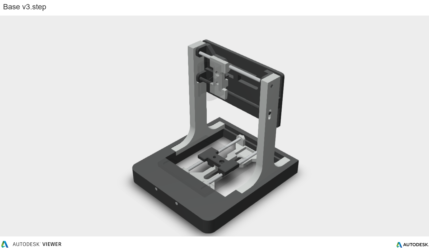
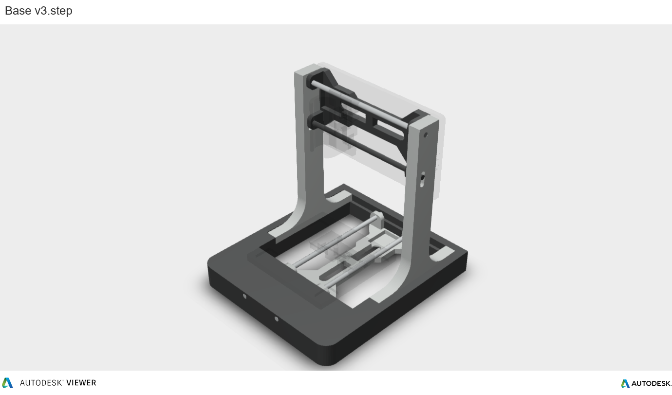
3D Model
To make our CNC – Mini Laser Engraver we need to 3D print some parts once you have printed them we can start assembling the CNC – Mini Laser Engraver.


 Download 3D Files
 |
Back Plate.stl | DOWNLOAD |
 |
Base.stl | DOWNLOAD |
 |
Cable Guide.stl | DOWNLOAD |
 |
Frame_Side_Left.stl | DOWNLOAD |
|
Frame_Side_Right.stl | DOWNLOAD |
 |
Laser Holder.stl | DOWNLOAD |
 |
Rail_Frame_One.stl | DOWNLOAD |
|
Rail_Frame_Two.stl | DOWNLOAD |
 |
Slider_One.stl | DOWNLOAD |
|
Slider_Two.stl | DOWNLOAD |
 |
Thread_Guide_one.stl | DOWNLOAD |
|
Thread_Guide_two.stl | DOWNLOAD |
 |
X_Plate.stl | DOWNLOAD |
You can download all .STL files here or go to : https://www.thingiverse.com/thing:3521286 (Original project)
All Parts are printed in ABS material.
Print Settings:
- Layer height: 0.2mm
- Infill: < 25%
- Supports: No
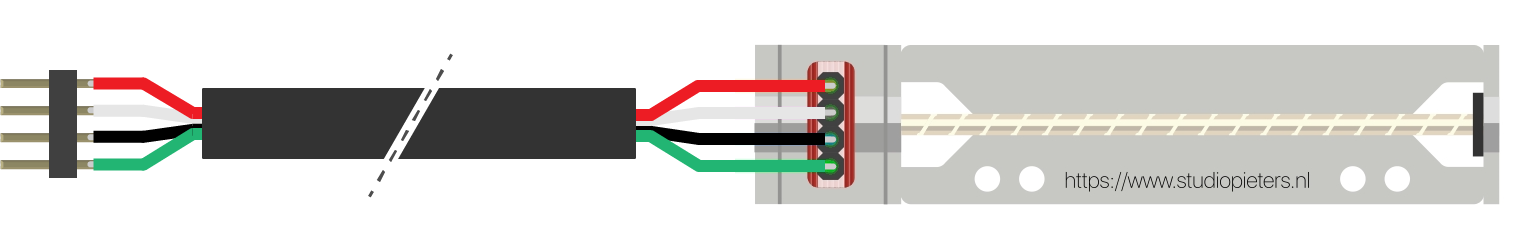
Wiring of Stepper Motors
For the stepper motors I’ve used old USB cable, because it has 4 wire inside and have a cover on it, and it is more flexible and easy to work with. Using Set the multi-meter to ‘Continuity‘ mode. It may vary among DMMs, but look for a diode symbol with propagation waves around it (like sound coming from a speaker). in Multi-meter determine determine 2 Coil, Coil A and Coil B. Soldered them and used pin header on the end.

Preparing the Sliders
We start with these parts.
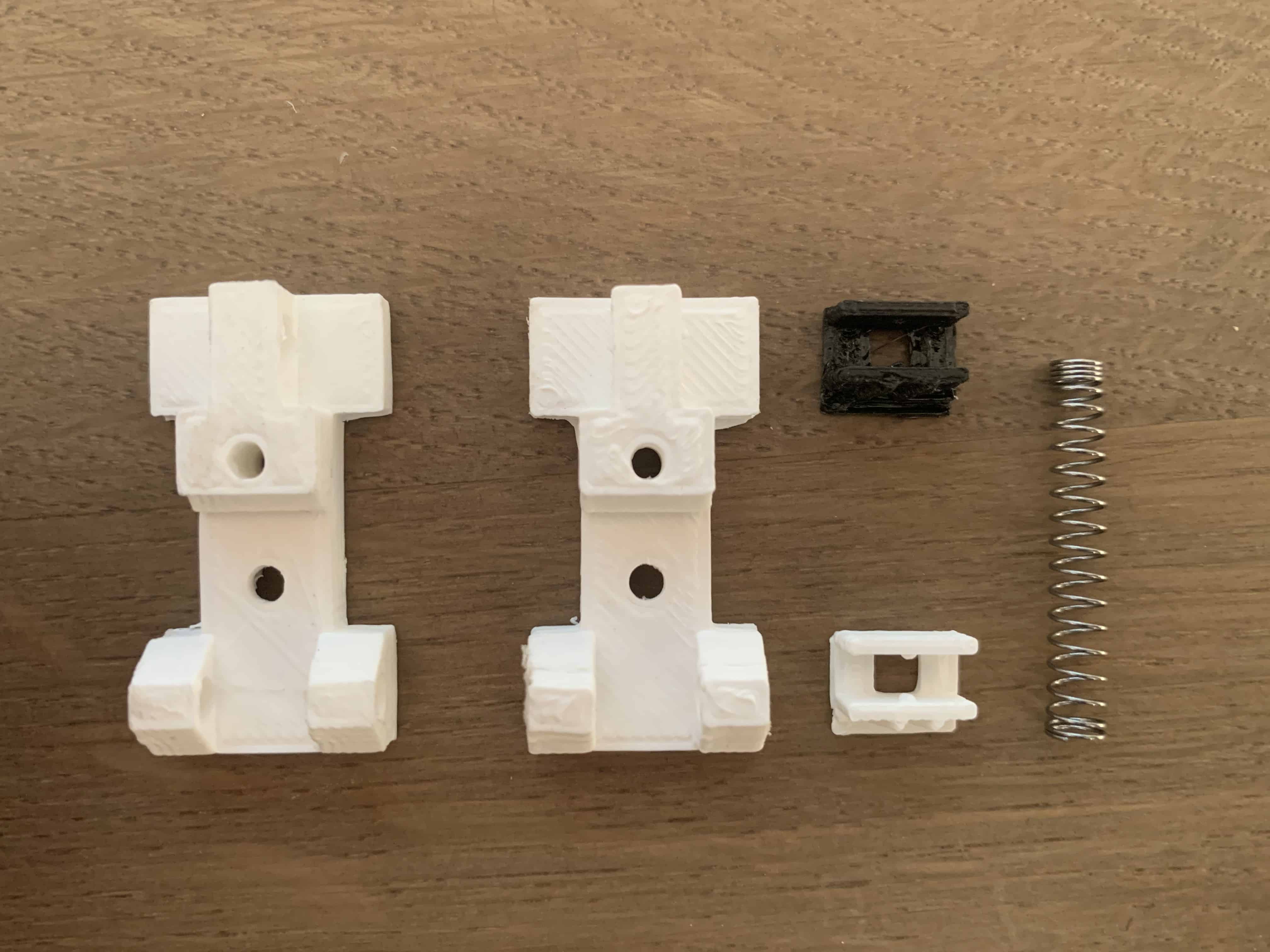 First superglue the Thread guide to the Slider
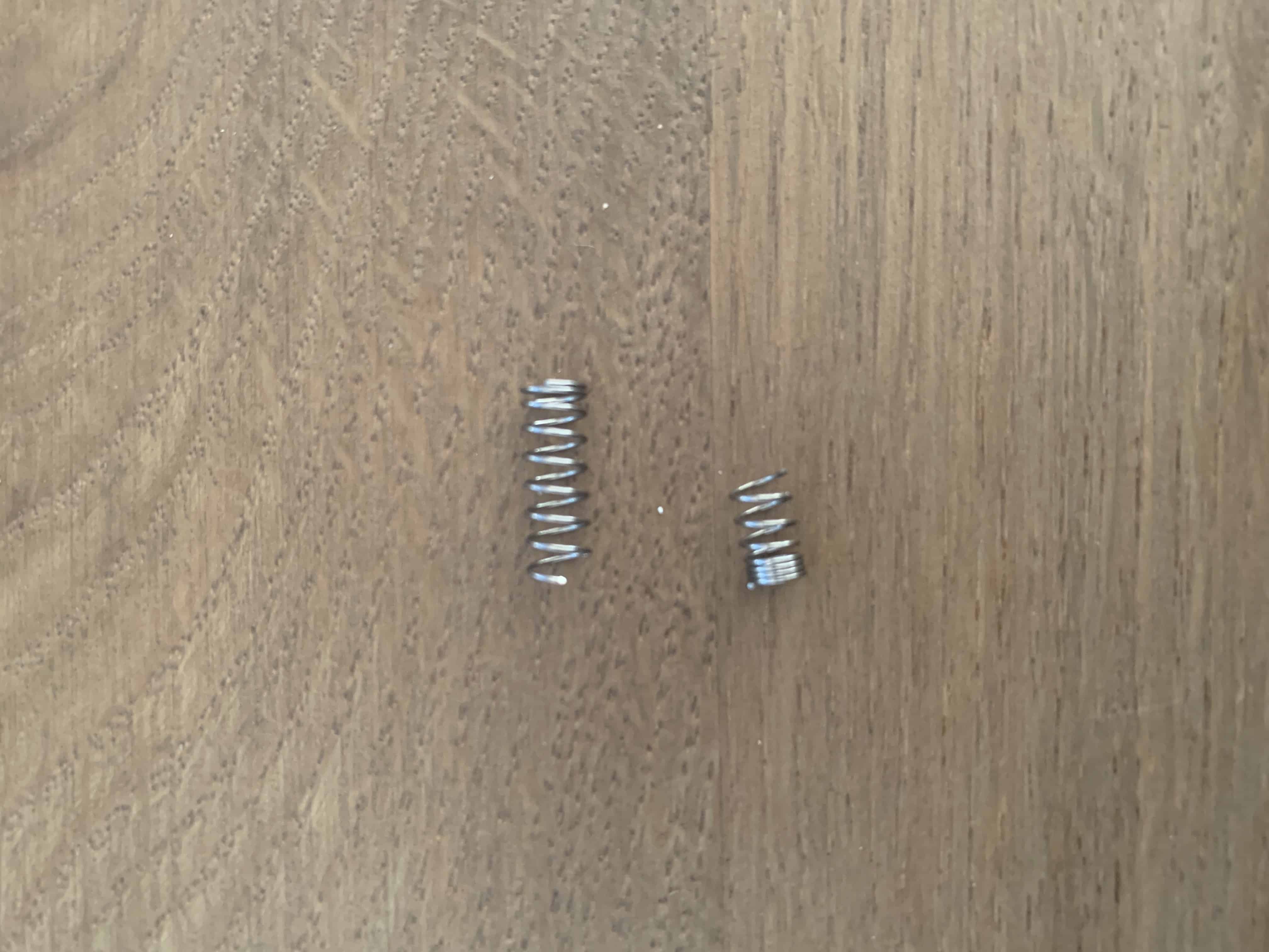
 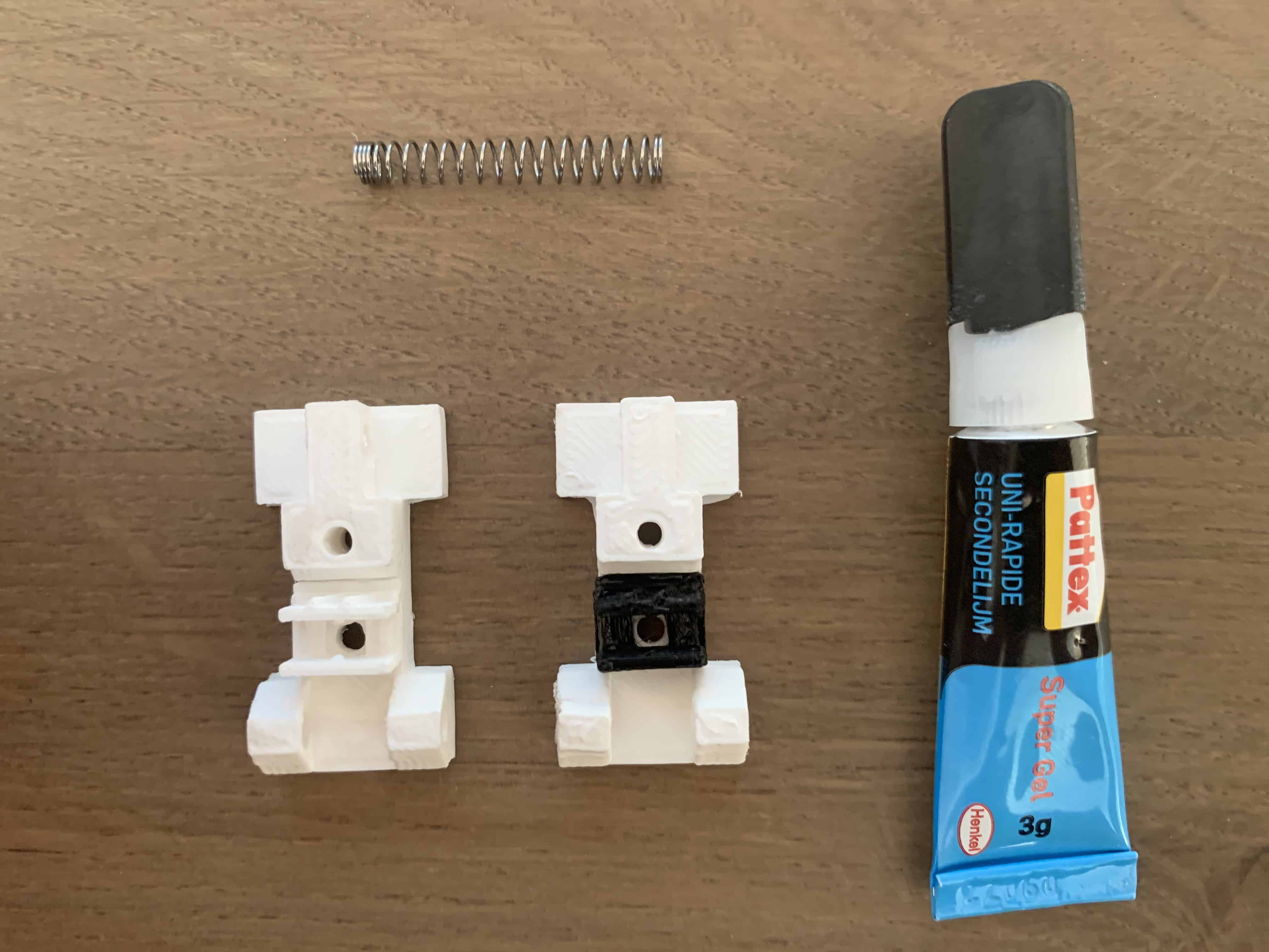 For the spring, I used one from a old ballpoint pen. Measure the length by compressing the spring. Then cut it to the desired length.
 Then place the spring Thread guide like in the image below. Spring is attached to maintain the tension between the guide and the lead screw to avoid black-lash.
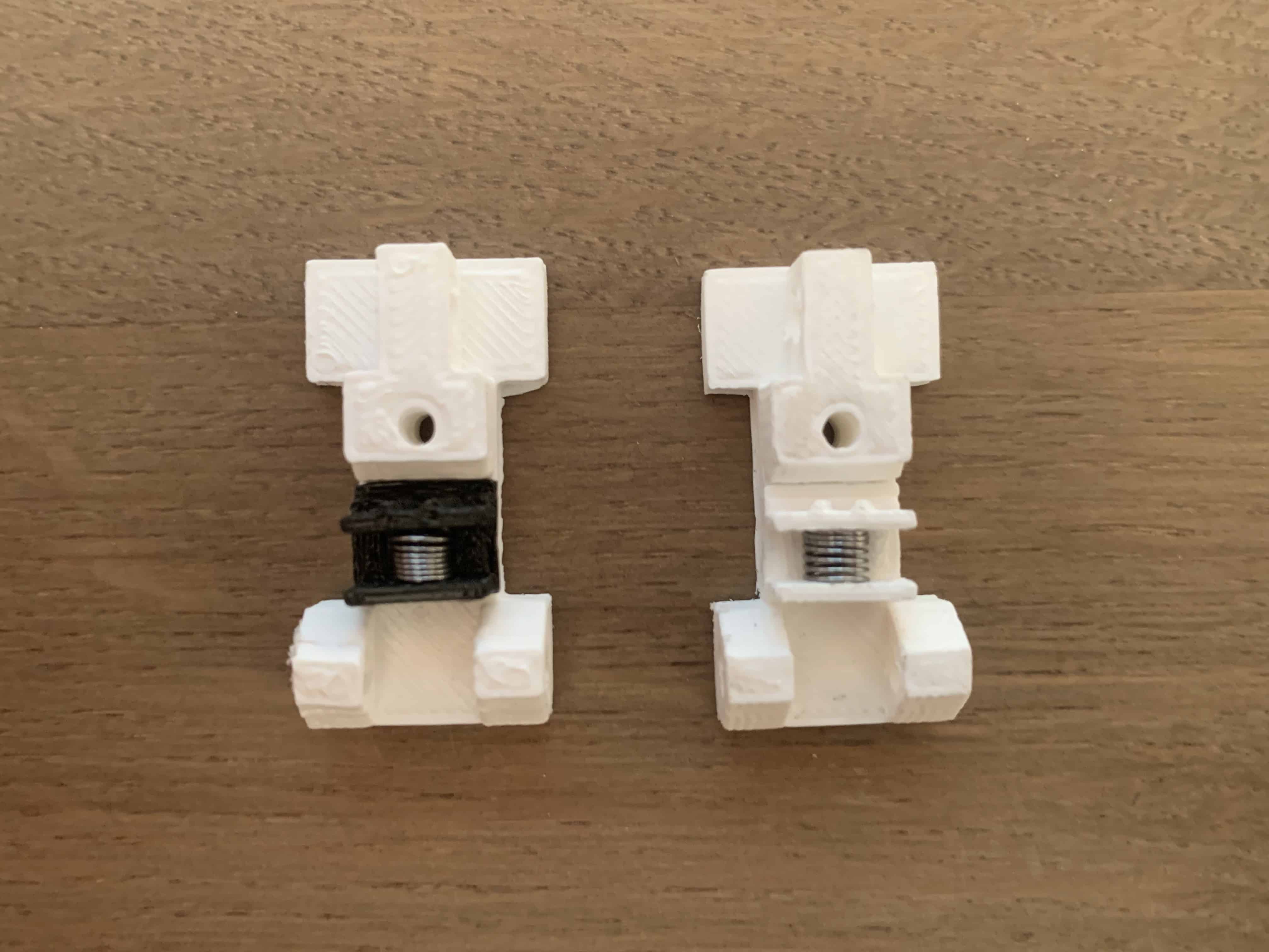 Now take one of the two CD / DVD driver mechanism.
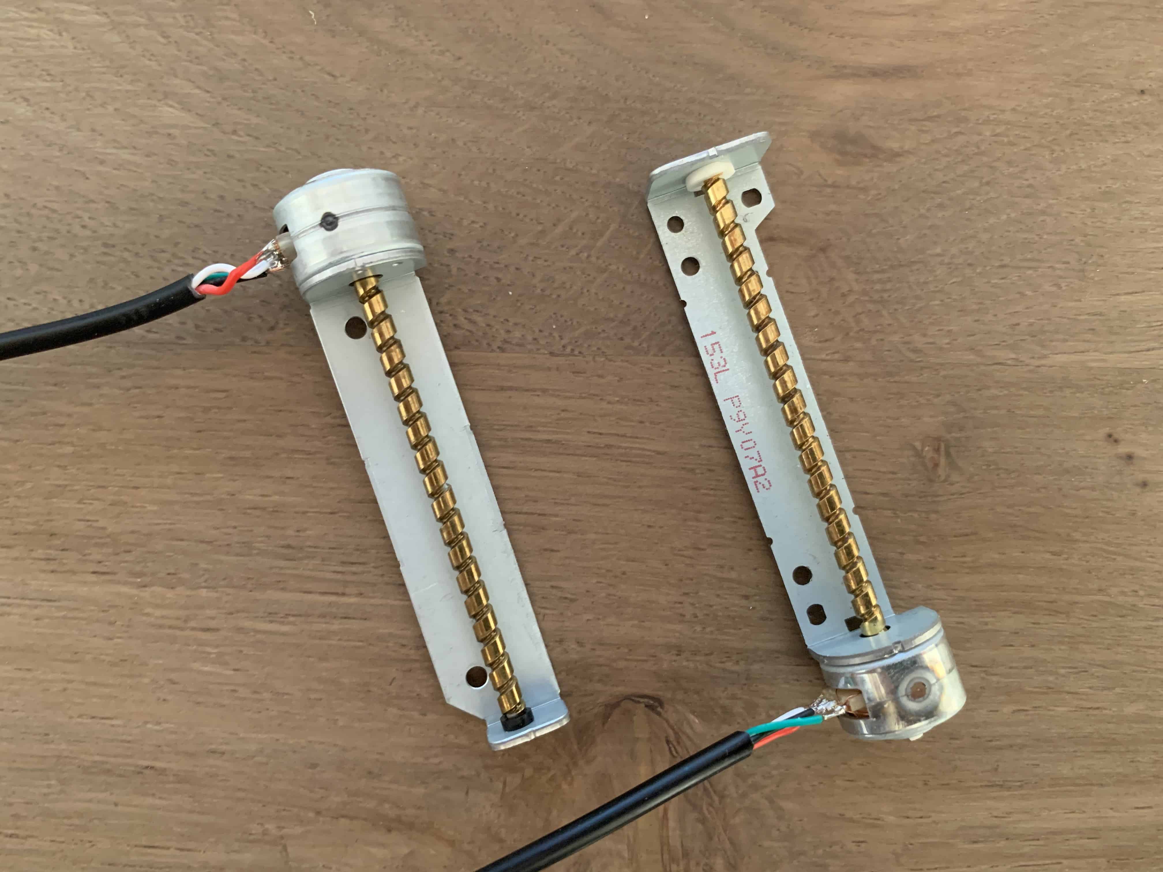
And supergluing it to the Slider like in the image below.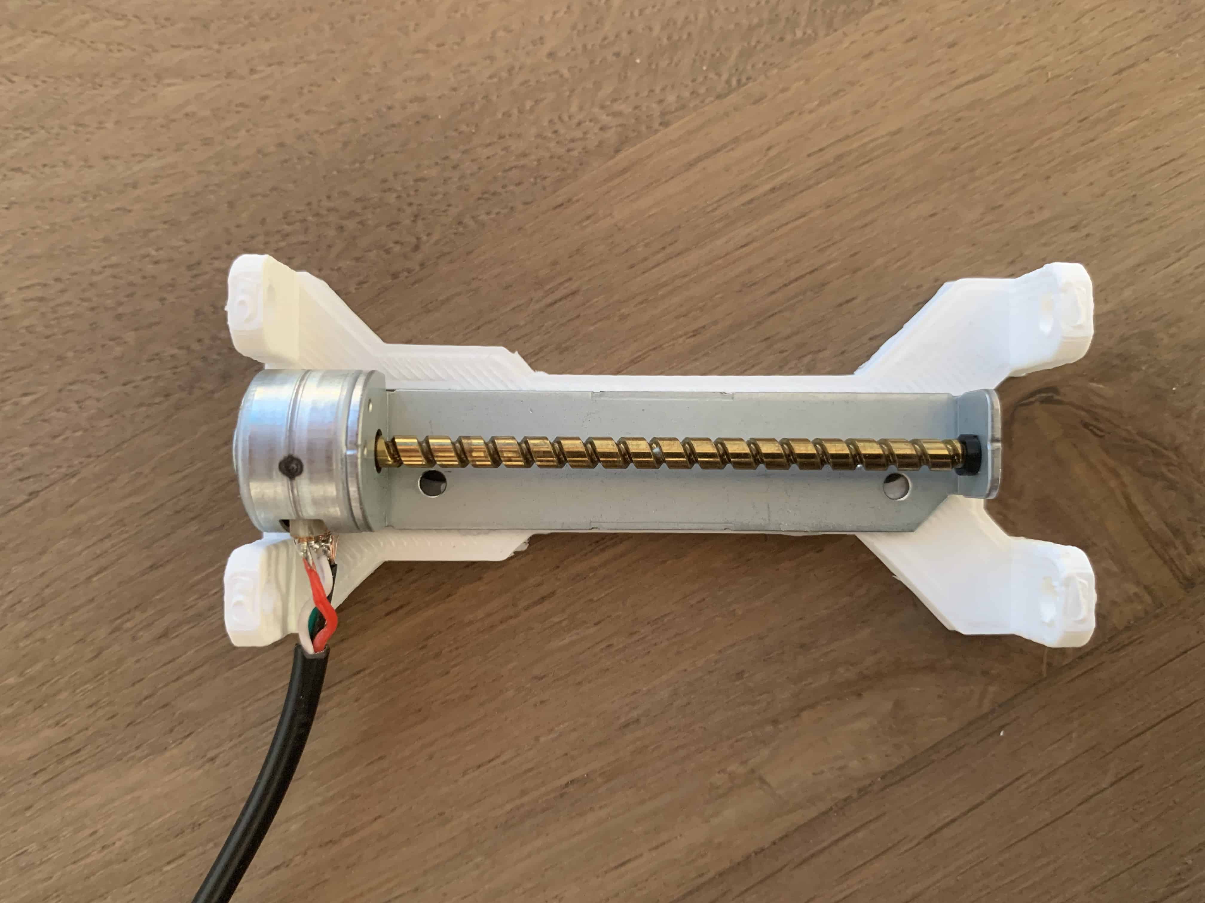

Assembling the Slider Rails for the Y-Axis
Place the Slider into the the Base. Make sure you align the holes for the rods later on.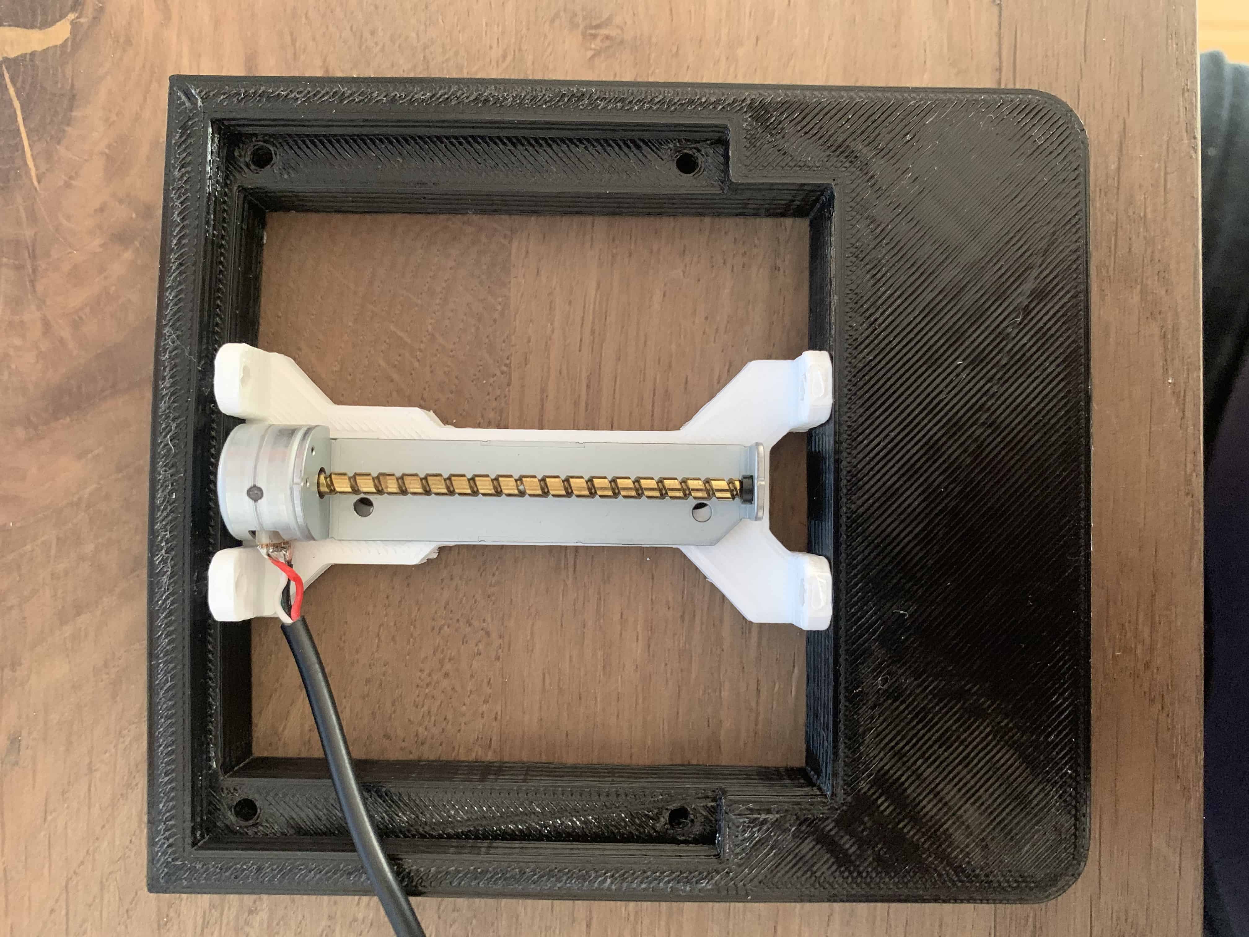
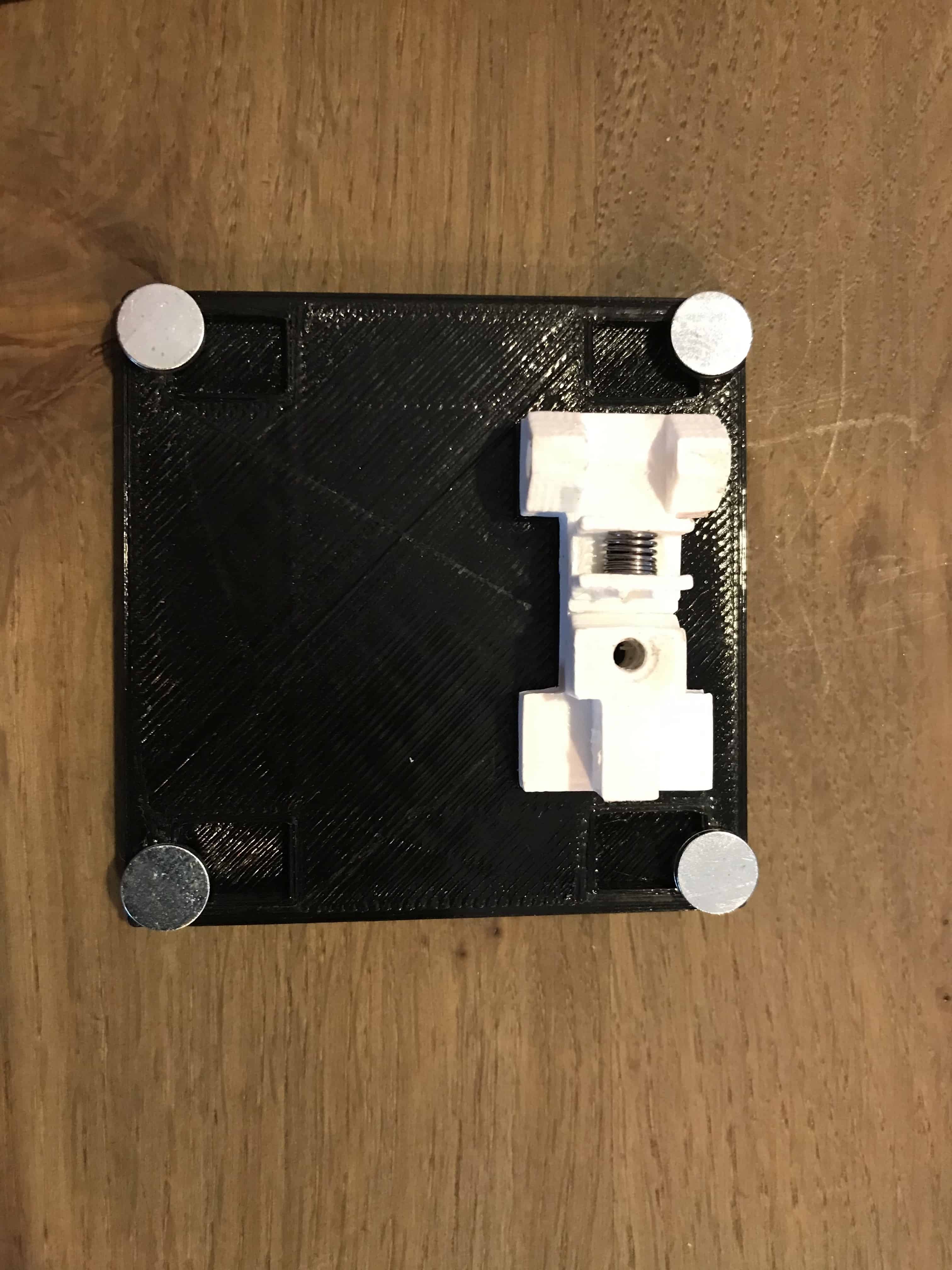
At the back of the X_Plate you can place the Slider on the back with superglue or with a small long enough screw.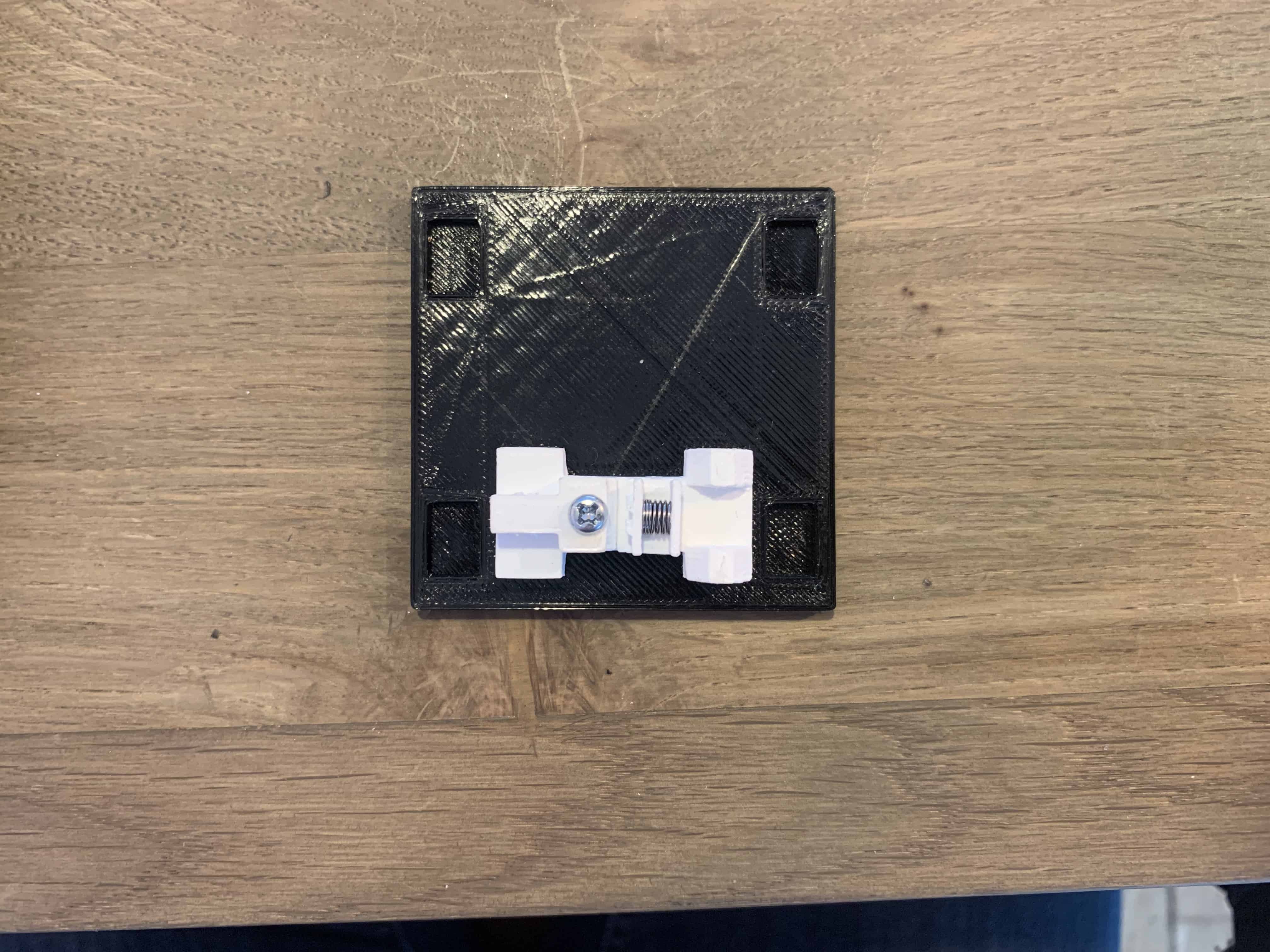 Before assembling the slider into the base I’ve glued 4x small neodymium magnets ( which I hade of an old project) onto the X_Plate. This magnets will helps in holding the work piece to the working area.
 Now we can place the rods,only put them half way in, like in the image below.
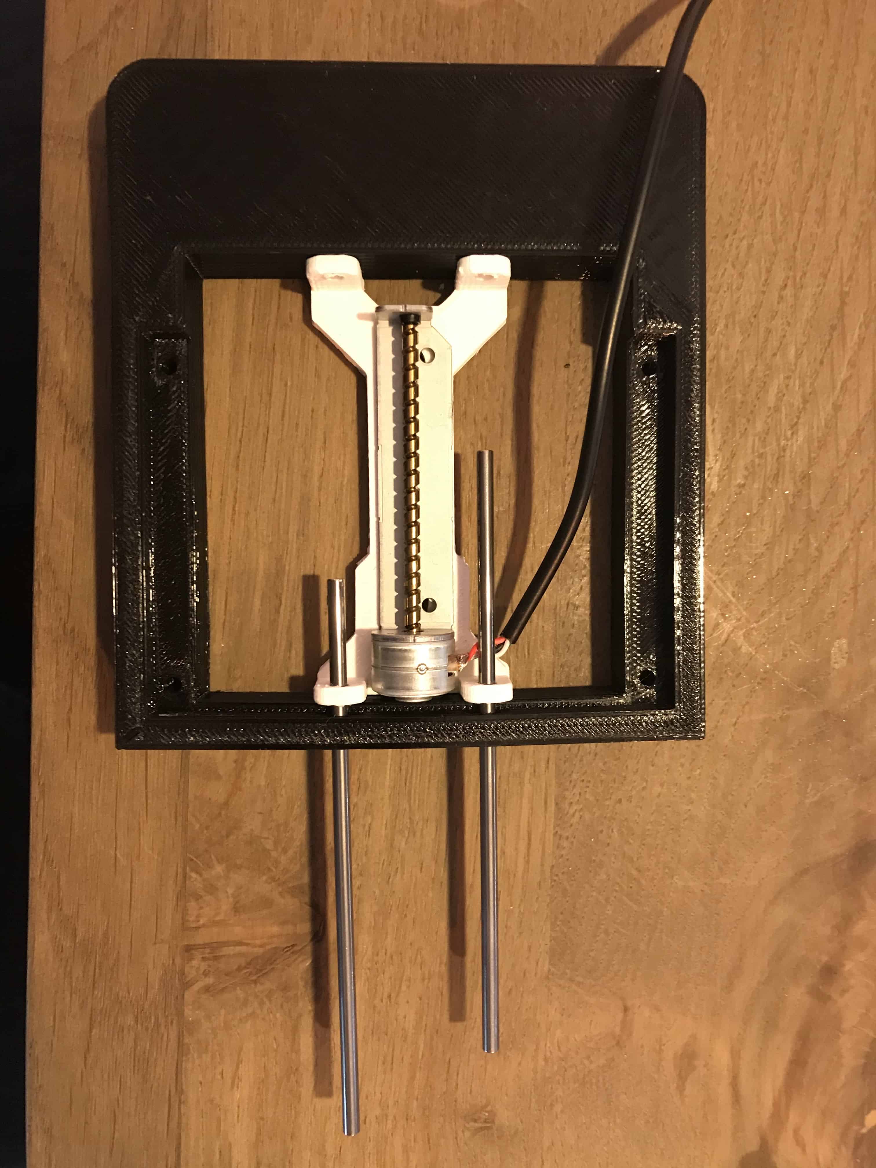 Now you can place the X_Plate and the Slider on the Stepper and push the rod’s trough.
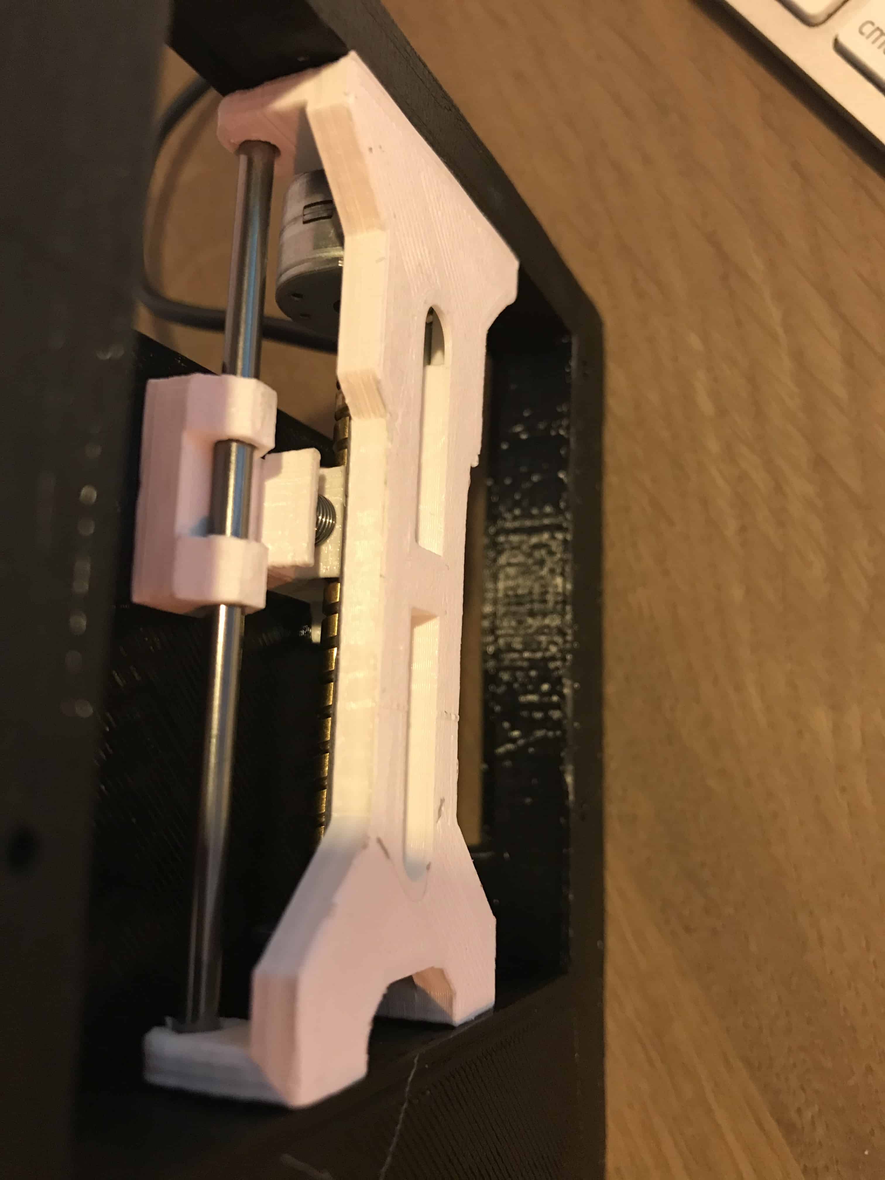 The smooth rod will keep the sliding mechanism in place.


Assembling the Slider Rails for the X-Axis
For the X-axis we need the other CD / DVD driver mechanism. The other Slider and Base.
 And super gluing it to the Slider like in the image below.
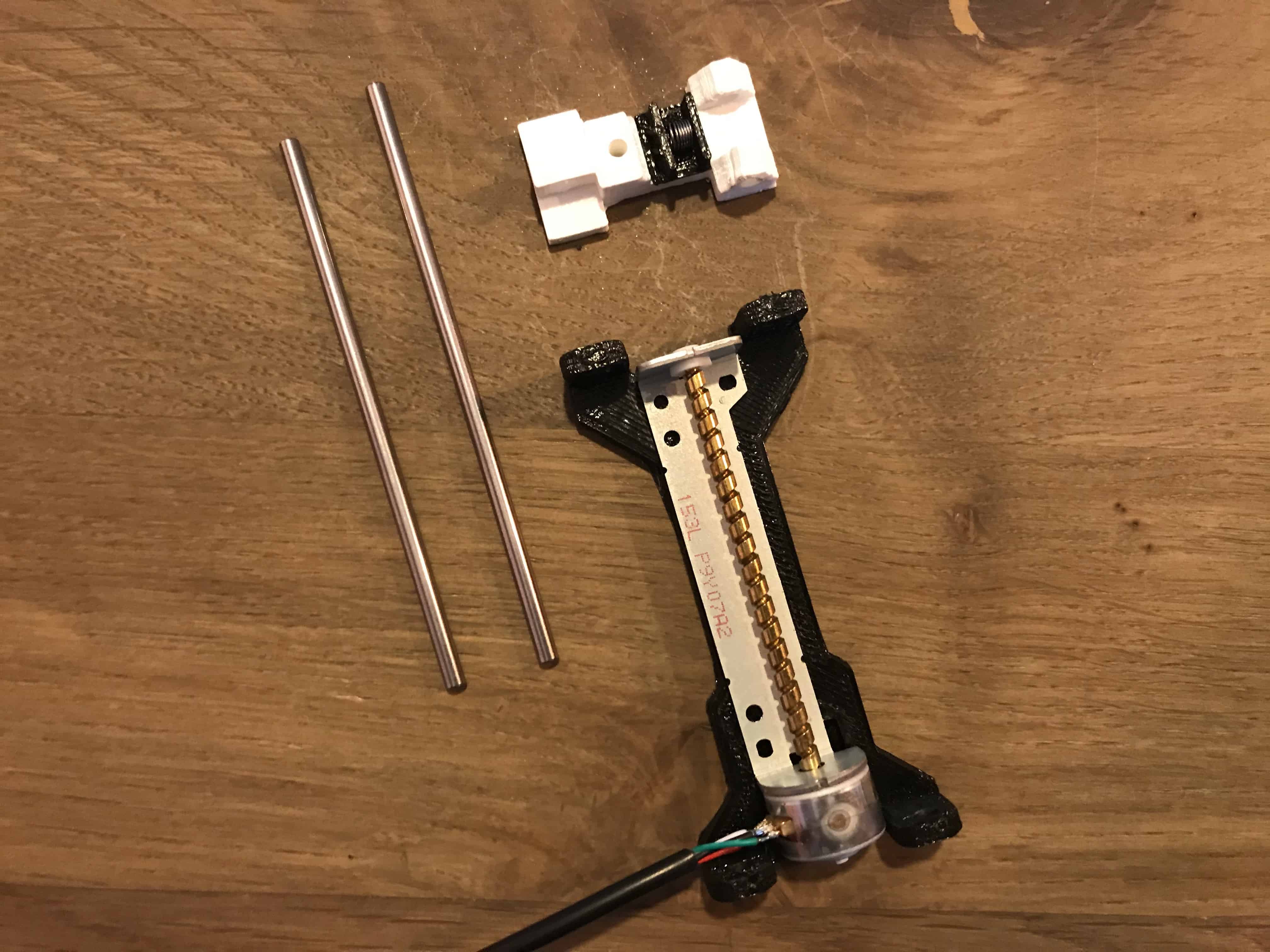 Inserted the smooth rods and guiding part into the holes given by keeping in mind that slider is moving freely not too hard.
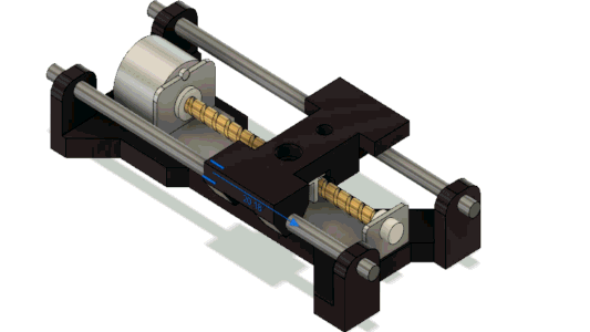


Combing the X and Y Axis
Using some superglue, combined the base and two side frame into one assembly.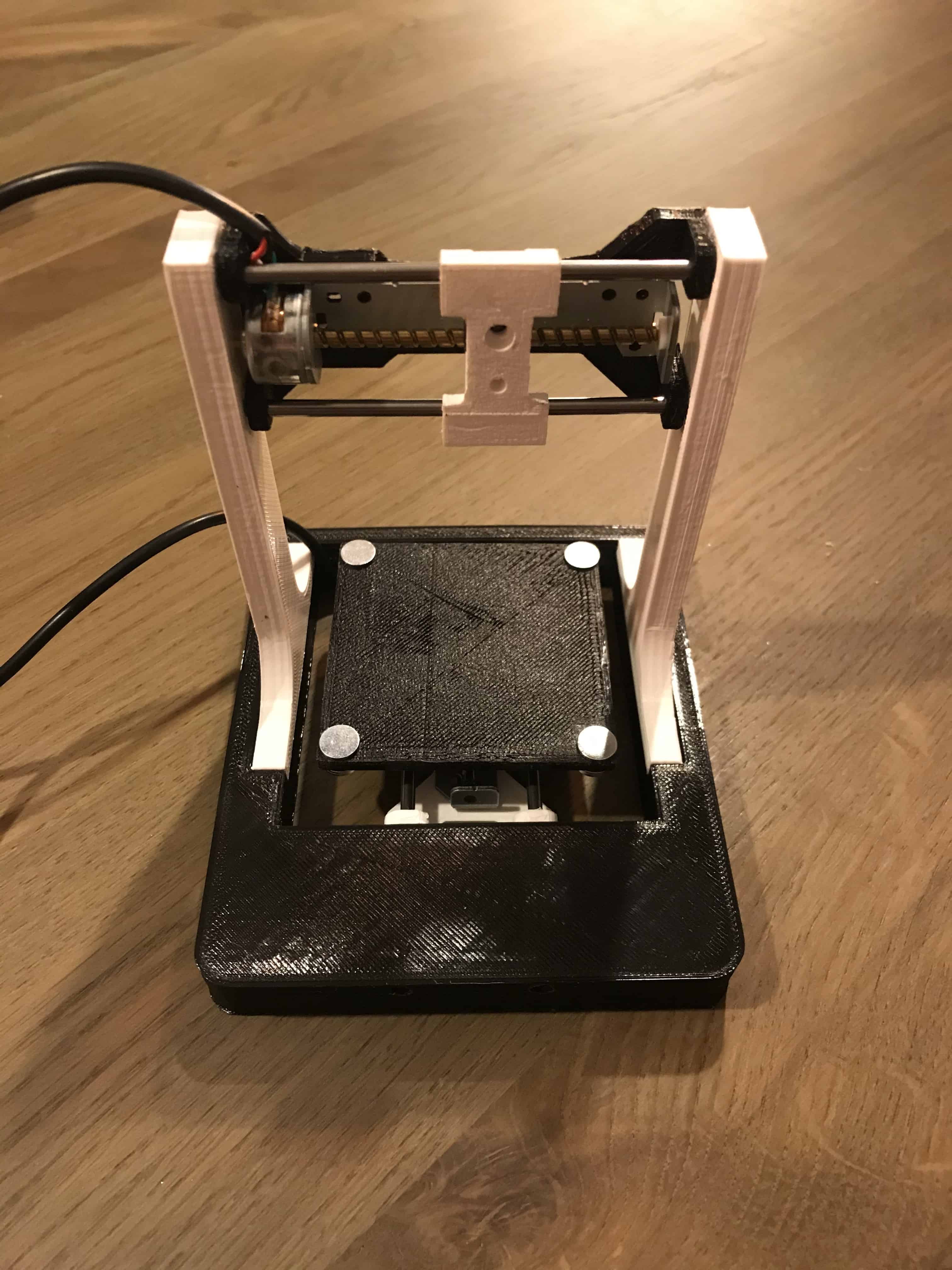
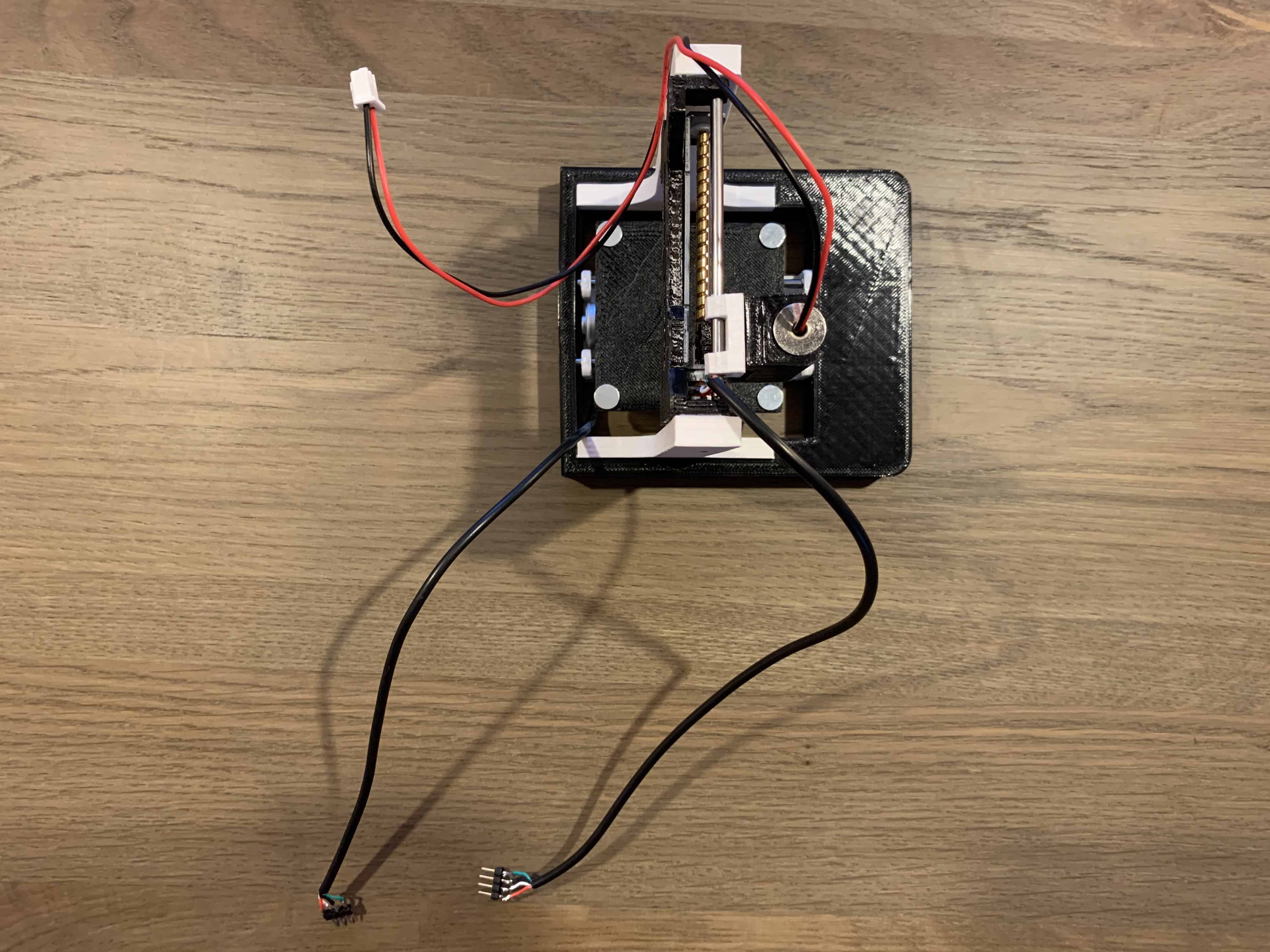
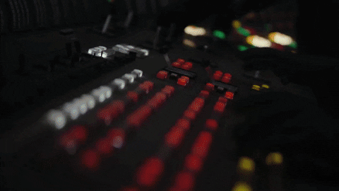
The Electronics
I made my setup on a breadboard. You can make your own PCB and place it on the back of the engraver. There is a Back Plate. If printed it you can use it to fit you PCB.
- Arduino Nano.
- 2 x DVR8825 Stepper motor drivers.
- 1 x IRFZ44N N-CHANNEL MOSFET.
- 1 x LM7805 Voltage regulator with Heat-sink.
- 1 x 47Ω resistor.
- 1 x 10kΩ resistor.
- 1 x 1000 µF 16V capacitor.
- 1 x Power jack
- 2 x 4 Male Header Pins.
- 1 x Breadboard & wires
- 1 x Power-supply 12V ~ 2A
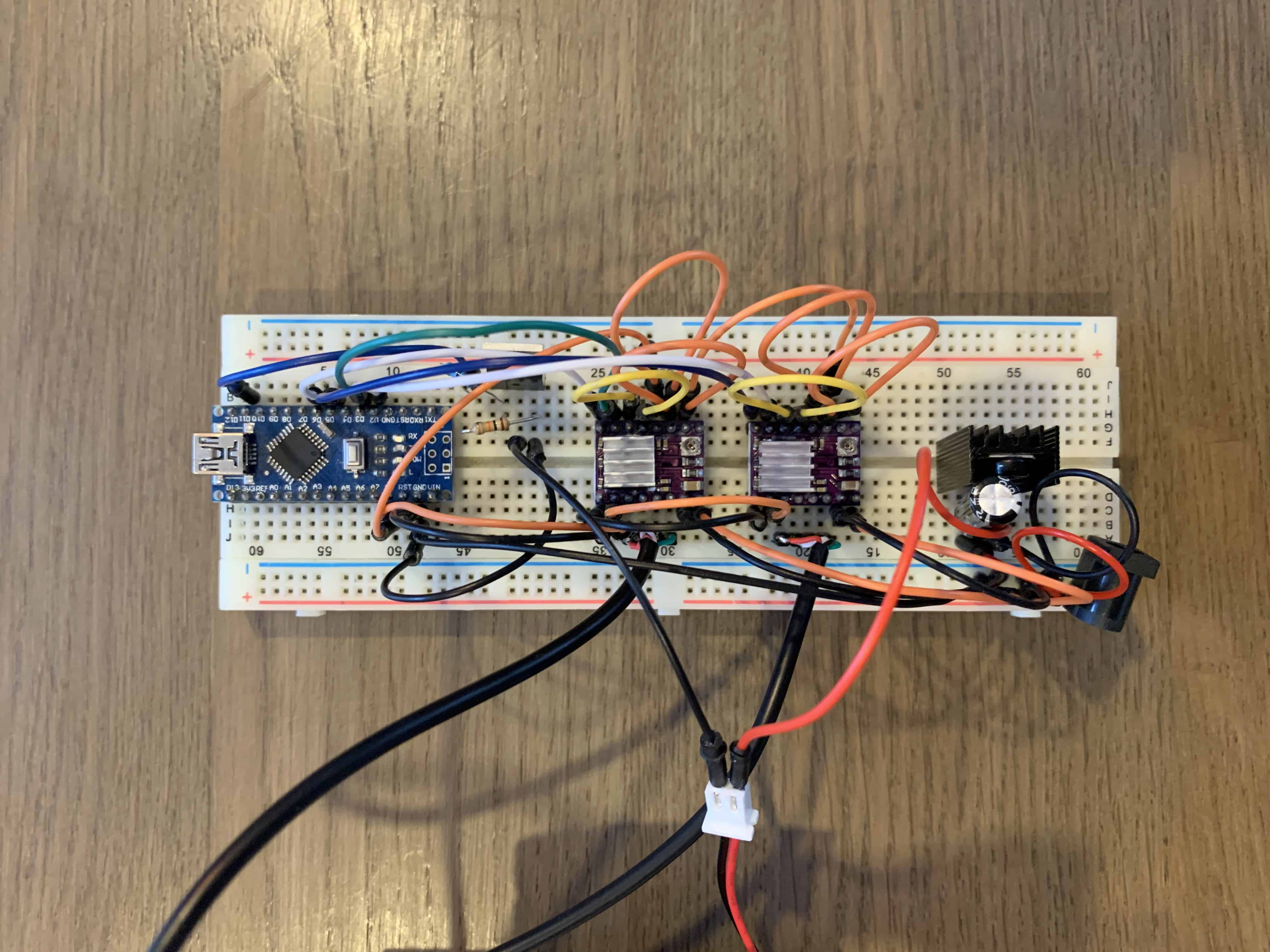
In GRBL the digital and analogue Pins of Arduino are reserved. The ‘Step‘ pin for the X and Y axes is attached to digital pins D2,and D3 respectively. The ‘Dir‘ pin for the X and Y axes is attached to digital pins D5 and D6 respectively. D11 is for laser Enable. The Arduino gets power through the USB Cable. The DVR8825 Drivers through external power source. All ground share common connections. VDD of DVR8825 are connected to 5V of Arduino. The laser I’ve used runs on 5V and has built in constant current circuit. For the constant 5V source from the external power supply LM7805 voltage regulator is used. Heat-sink is compulsory. The IRFZ44N N-CHANNEL MOSFET works as an electronic switch when receives digital high signal from pin D11 of Arduino.

KiCAD Scheme
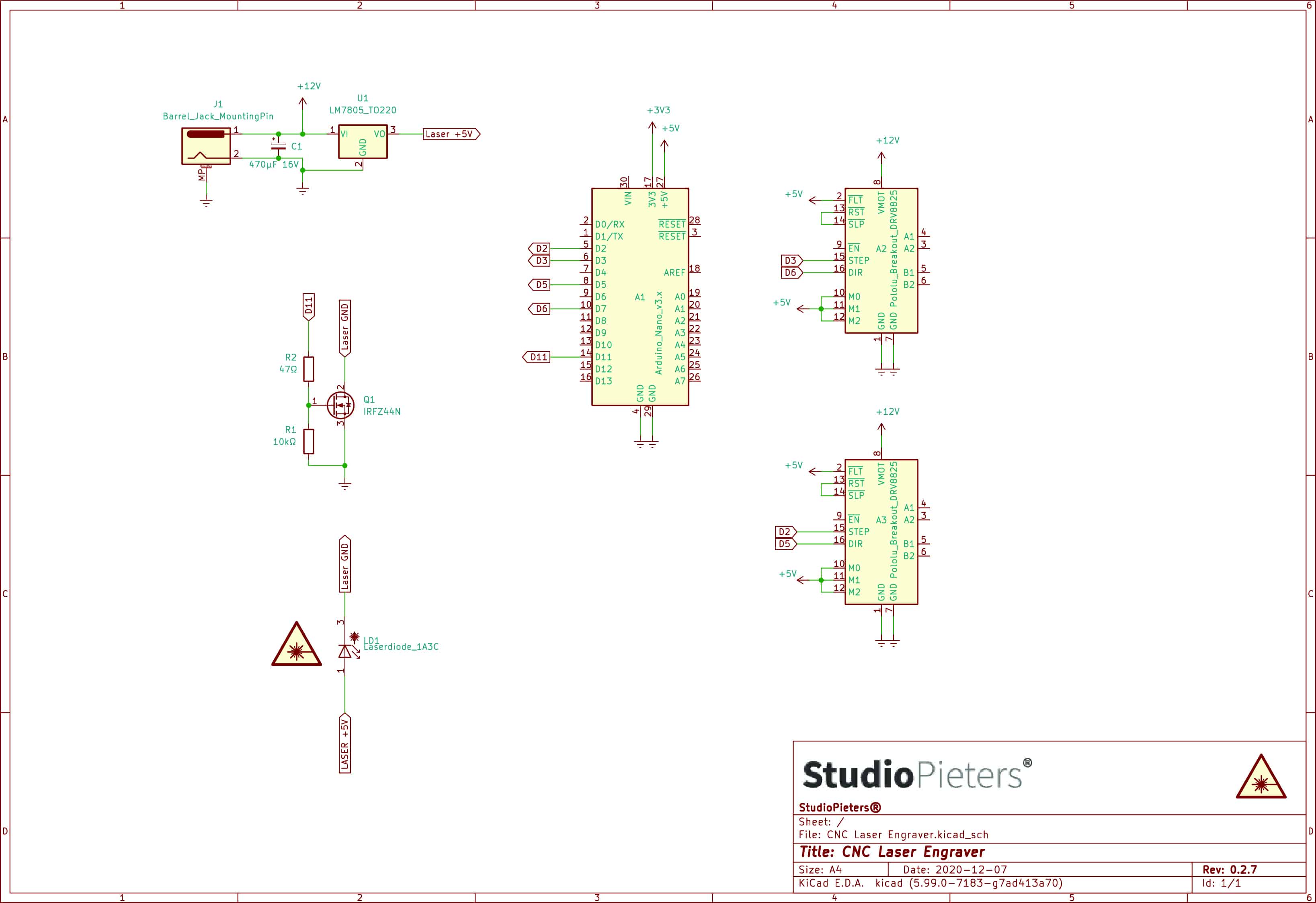
NOTE: 5V from Arduino nano can’t be used because the laser draws more than 250mA and the Arduino Nano is not capable of delivering that much of current.
Configuring Micro Stepping for Each Axis
The 3 pins (MS0, MS1 and MS2) are for selecting one of the five step resolutions according to the truth table. These pins have internal pull-down resistors so if we leave them disconnected, the board will operate in full step mode. I’ve used the 16th step configuration for smooth and noise free.
| MS0 | MS1 | MS2 | Microstep Resolution |
| Low | Low | Low | Full Step |
| High | Low | Low | Half Step |
| Low | High | Low | Quarter Step |
| High | High | Low | Eight Step |
| High | High | High | Sixteenth Step |
Most (but certainly not all) stepper motors do 200 full steps per revolution. By appropriately managing the current in the coils it is possible to make the motor move in smaller steps. The DVR8825 can make the motor move in 1/16th steps – or 3,200 steps per revolution.The main advantage of micro-stepping is to reduce the roughness of the motion. The only fully accurate positions are the full-step positions. The motor will not be able to hold a stationary position at one of the intermediate positions with the same position accuracy or with the same holding torque as at the full step positions.Generally speaking when high speeds are required full steps should be used.
Adjusting the Stepper Driver Current
To achieve high step rates, the motor supply is typically much higher than would be permissible without active current limiting. For instance, a typical stepper motor might have a maximum current rating of 1A with a 5Ω coil resistance, which would indicate a maximum motor supply of 5 V. Using such a motor with 12 V would allow higher step rates, but the current must actively be limited to under 1A to prevent damage to the motor.
The DVR8825 supports such active current limiting, and the trimmer potentiometer on the board can be used to set the current limit. One way to set the current limit is to put the driver into full-step mode and to measure the current running through a single motor coil without clocking the STEP input.

The measured current will be 0.7 times the current limit (since both coils are always on and limited to 70% of the current limit setting in full-step mode). Please note that changing the logic voltage, Vdd, to a different value will change the current limit setting since the voltage on the “ref” pin is a function of Vdd. Another way to set the current limit is to measure the voltage directly on top of the potentiometer and to calculate the resulting current limit (the current sense resistors are 0.1Ω).
The current limit relates to the reference voltage as follows:
Current Limit = VREF × 1.25
So, for example, if the reference voltage is 0.6 V, the current limit is 0.75A. As mentioned above, in full step mode, the current through the coils is limited to 70% of the current limit, so to get a full-step coil current of 1A, the current limit should be 1A / 0.7 = 1.4A, which corresponds to a VREF of 1.4A / 1.25 = 1.12V. See the DVR8825 datasheet for more information.
Note: The coil current can be very different from the power supply current, so you should not use the current measured at the power supply to set the current limit. The appropriate place to put your current meter is in series with one of your stepper motor coils.
GRBL Firmware
Grbl is a no-compromise, high performance, low cost alternative to parallel-port-based motion control for CNC milling. It will run on a vanilla Arduino (Duemillanove/Uno) as long as it sports an Atmega 328.
The controller is written in highly optimized C utilizing every clever feature of the AVR-chips to achieve precise timing and asynchronous operation. It is able to maintain up to 30kHz of stable, jitter free control pulses.
It accepts standards-compliant g-code and has been tested with the output of several CAM tools with no problems. Arcs, circles and helical motion are fully supported, as well as, all other primary g-code commands. Macro functions, variables, and most canned cycles are not supported, but we think GUIs can do a much better job at translating them into straight g-code anyhow.
Grbl includes full acceleration management with look ahead. That means the controller will look up to 18 motions into the future and plan its velocities ahead to deliver smooth acceleration and jerk-free cornering.
Licensing: Grbl is free software, released under the GPLv3 license.
Download the GRBL , Here
Once downloaded extract on the desktop the grbl-master folder, you find it in the file master.zip. hen downloading on a Mac it will extract automatically.
Run the Arduino IDE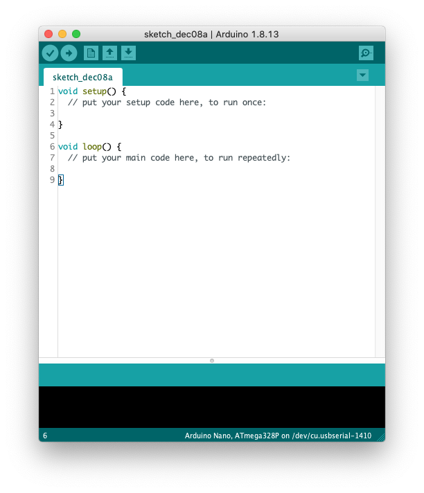 From the application bar menu, choose: Sketch -> include Library -> Add Library from file.ZIP…
 Select the folder grbl that you can find inside the grlb-master folder and click on Open
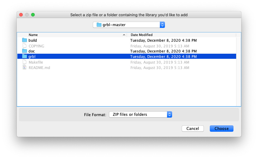 The library now is installed and the IDE software will show you this message: The library is added to your library. Check the “libraries Inclusion” menu. Then open an example called “grbl upload” and upload it to your Arduino board.
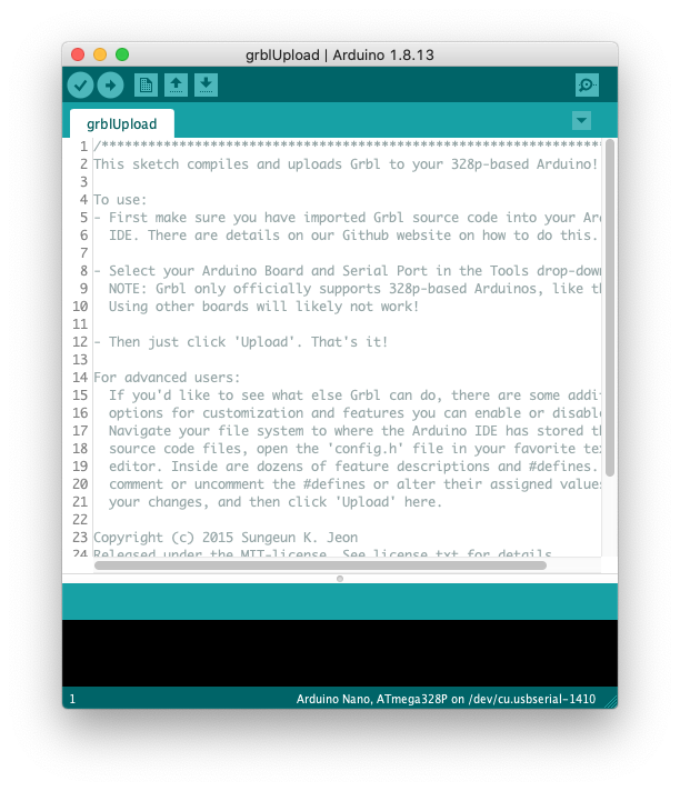
Press the upload button to flash your Arduino with the grbl firmware.
Software to Send G-CODE
Also we need a software to send G-Code to CNC for that I’ve used the Universal Gcode Sender.

A full featured gcode platform used for interfacing with advanced CNC controllers like GRBL , TinyG, g2core and Smoothieware. Universal Gcode Sender is a self-contained Java application which includes all external dependencies and can be used on most computers running Windows, MacOSX or Linux.You can download UGS here.
Open UGS (Universal Gcode Sender).
 At the top after Firmware select GRBL.

Next after Port select your port you have your Arduino connected to.
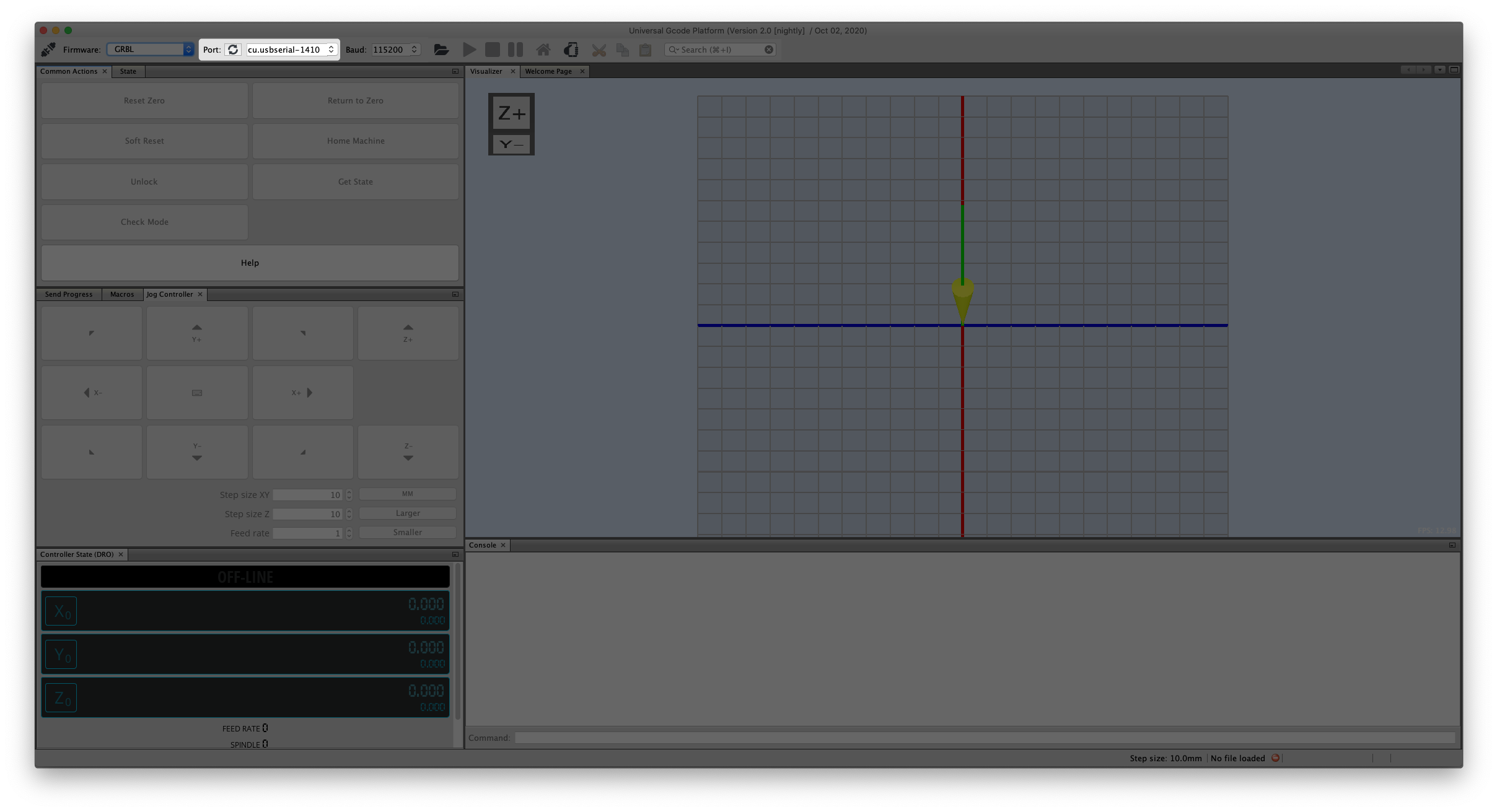
And at last set the Baud rate at 115200.
Now you can connect to your laser engraver by pressing the power plug icon.
GRBL Firmeware settings
Before we can use our CNC laser engraver we need to change some standard settings.
To view the settings, Go to Machine -> Firmware Settings after connecting to GRBL.

GRBL should respond with a list of the current system settings, as shown in the example below. All of these settings are persistent and kept in EEPROM, so if you power down, these will be loaded back up the next time you power up your Arduino.
 Export the settings by clicking the Export button. Save these settings with the extension .old.
firmware.settings.old
{
  "name": "Exported settings",
  "createdBy": "achimpieters",
  "date": "2020-12-02",
  "firmwareName": "Grbl 1.1h",
  "settings": [
    {
      "key": "$30",
      "value": "1000",
      "units": "RPM",
      "description": "Maximum spindle speed. Sets PWM to 100% duty cycle.",
      "shortDescription": "Maximum spindle speed"
    },
    {
      "key": "$31",
      "value": "0",
      "units": "RPM",
      "description": "Minimum spindle speed. Sets PWM to 0.4% or lowest duty cycle.",
      "shortDescription": "Minimum spindle speed"
    },
    {
      "key": "$10",
      "value": "1",
      "units": "mask",
      "description": "Alters data included in status reports.",
      "shortDescription": "Status report options"
    },
    {
      "key": "$32",
      "value": "0",
      "units": "boolean",
      "description": "Enables laser mode. Consecutive G1/2/3 commands will not halt when spindle speed is changed.",
      "shortDescription": "Laser-mode enable"
    },
    {
      "key": "$11",
      "value": "0.010",
      "units": "millimeters",
      "description": "Sets how fast Grbl travels through consecutive motions. Lower value slows it down.",
      "shortDescription": "Junction deviation"
    },
    {
      "key": "$12",
      "value": "0.002",
      "units": "millimeters",
      "description": "Sets the G2 and G3 arc tracing accuracy based on radial error. Beware: A very small value may effect performance.",
      "shortDescription": "Arc tolerance"
    },
    {
      "key": "$13",
      "value": "0",
      "units": "boolean",
      "description": "Enables inch units when returning any position and rate value that is not a settings value.",
      "shortDescription": "Report in inches"
    },
    {
      "key": "$0",
      "value": "10",
      "units": "microseconds",
      "description": "Sets time length per step. Minimum 3usec.",
      "shortDescription": "Step pulse time"
    },
    {
      "key": "$1",
      "value": "25",
      "units": "milliseconds",
      "description": "Sets a short hold delay when stopping to let dynamics settle before disabling steppers. Value 255 keeps motors enabled with no delay.",
      "shortDescription": "Step idle delay"
    },
    {
      "key": "$2",
      "value": "0",
      "units": "mask",
      "description": "Inverts the step signal. Set axis bit to invert (00000ZYX).",
      "shortDescription": "Step pulse invert"
    },
    {
      "key": "$3",
      "value": "0",
      "units": "mask",
      "description": "Inverts the direction signal. Set axis bit to invert (00000ZYX).",
      "shortDescription": "Step direction invert"
    },
    {
      "key": "$4",
      "value": "0",
      "units": "boolean",
      "description": "Inverts the stepper driver enable pin signal.",
      "shortDescription": "Invert step enable pin"
    },
    {
      "key": "$5",
      "value": "0",
      "units": "boolean",
      "description": "Inverts the all of the limit input pins.",
      "shortDescription": "Invert limit pins"
    },
    {
      "key": "$6",
      "value": "0",
      "units": "boolean",
      "description": "Inverts the probe input pin signal.",
      "shortDescription": "Invert probe pin"
    },
    {
      "key": "$120",
      "value": "10.000",
      "units": "mm/sec^2",
      "description": "X-axis acceleration. Used for motion planning to not exceed motor torque and lose steps.",
      "shortDescription": "X-axis acceleration"
    },
    {
      "key": "$100",
      "value": "250.000",
      "units": "step/mm",
      "description": "X-axis travel resolution in steps per millimeter.",
      "shortDescription": "X-axis travel resolution"
    },
    {
      "key": "$122",
      "value": "10.000",
      "units": "mm/sec^2",
      "description": "Z-axis acceleration. Used for motion planning to not exceed motor torque and lose steps.",
      "shortDescription": "Z-axis acceleration"
    },
    {
      "key": "$121",
      "value": "10.000",
      "units": "mm/sec^2",
      "description": "Y-axis acceleration. Used for motion planning to not exceed motor torque and lose steps.",
      "shortDescription": "Y-axis acceleration"
    },
    {
      "key": "$102",
      "value": "250.000",
      "units": "step/mm",
      "description": "Z-axis travel resolution in steps per millimeter.",
      "shortDescription": "Z-axis travel resolution"
    },
    {
      "key": "$101",
      "value": "250.000",
      "units": "step/mm",
      "description": "Y-axis travel resolution in steps per millimeter.",
      "shortDescription": "Y-axis travel resolution"
    },
    {
      "key": "$20",
      "value": "0",
      "units": "boolean",
      "description": "Enables soft limits checks within machine travel and sets alarm when exceeded. Requires homing.",
      "shortDescription": "Soft limits enable"
    },
    {
      "key": "$21",
      "value": "0",
      "units": "boolean",
      "description": "Enables hard limits. Immediately halts motion and throws an alarm when switch is triggered.",
      "shortDescription": "Hard limits enable"
    },
    {
      "key": "$22",
      "value": "0",
      "units": "boolean",
      "description": "Enables homing cycle. Requires limit switches on all axes.",
      "shortDescription": "Homing cycle enable"
    },
    {
      "key": "$23",
      "value": "0",
      "units": "mask",
      "description": "Homing searches for a switch in the positive direction. Set axis bit (00000ZYX) to search in negative direction.",
      "shortDescription": "Homing direction invert"
    },
    {
      "key": "$24",
      "value": "25.000",
      "units": "mm/min",
      "description": "Feed rate to slowly engage limit switch to determine its location accurately.",
      "shortDescription": "Homing locate feed rate"
    },
    {
      "key": "$25",
      "value": "500.000",
      "units": "mm/min",
      "description": "Seek rate to quickly find the limit switch before the slower locating phase.",
      "shortDescription": "Homing search seek rate"
    },
    {
      "key": "$26",
      "value": "250",
      "units": "milliseconds",
      "description": "Sets a short delay between phases of homing cycle to let a switch debounce.",
      "shortDescription": "Homing switch debounce delay"
    },
    {
      "key": "$27",
      "value": "1.000",
      "units": "millimeters",
      "description": "Retract distance after triggering switch to disengage it. Homing will fail if switch isn\u0027t cleared.",
      "shortDescription": "Homing switch pull-off distance"
    },
    {
      "key": "$131",
      "value": "200.000",
      "units": "millimeters",
      "description": "Maximum Y-axis travel distance from homing switch. Determines valid machine space for soft-limits and homing search distances.",
      "shortDescription": "Y-axis maximum travel"
    },
    {
      "key": "$130",
      "value": "200.000",
      "units": "millimeters",
      "description": "Maximum X-axis travel distance from homing switch. Determines valid machine space for soft-limits and homing search distances.",
      "shortDescription": "X-axis maximum travel"
    },
    {
      "key": "$111",
      "value": "500.000",
      "units": "mm/min",
      "description": "Y-axis maximum rate. Used as G0 rapid rate.",
      "shortDescription": "Y-axis maximum rate"
    },
    {
      "key": "$110",
      "value": "500.000",
      "units": "mm/min",
      "description": "X-axis maximum rate. Used as G0 rapid rate.",
      "shortDescription": "X-axis maximum rate"
    },
    {
      "key": "$132",
      "value": "200.000",
      "units": "millimeters",
      "description": "Maximum Z-axis travel distance from homing switch. Determines valid machine space for soft-limits and homing search distances.",
      "shortDescription": "Z-axis maximum travel"
    },
    {
      "key": "$112",
      "value": "500.000",
      "units": "mm/min",
      "description": "Z-axis maximum rate. Used as G0 rapid rate.",
      "shortDescription": "Z-axis maximum rate"
    }
  ]
}
Make the necessary changes the settings as shown below. Save these settings with the extension .settings. By clicking the import button. You can save it to your Arduino. You can also down load the file here.
But be careful: not all stepper are alike. It’s possible you have to tweak some settings.
firmware.settings
{
  "name": "Exported settings",
  "createdBy": "achimpieters",
  "date": "2020-12-02",
  "firmwareName": "Grbl 1.1h",
  "settings": [
    {
      "key": "$30",
      "value": "1000",
      "units": "RPM",
      "description": "Maximum spindle speed. Sets PWM to 100% duty cycle.",
      "shortDescription": "Maximum spindle speed"
    },
    {
      "key": "$31",
      "value": "0",
      "units": "RPM",
      "description": "Minimum spindle speed. Sets PWM to 0.4% or lowest duty cycle.",
      "shortDescription": "Minimum spindle speed"
    },
    {
      "key": "$10",
      "value": "3",
      "units": "mask",
      "description": "Alters data included in status reports.",
      "shortDescription": "Status report options"
    },
    {
      "key": "$32",
      "value": "0",
      "units": "boolean",
      "description": "Enables laser mode. Consecutive G1/2/3 commands will not halt when spindle speed is changed.",
      "shortDescription": "Laser-mode enable"
    },
    {
      "key": "$11",
      "value": "0.020",
      "units": "millimeters",
      "description": "Sets how fast Grbl travels through consecutive motions. Lower value slows it down.",
      "shortDescription": "Junction deviation"
    },
    {
      "key": "$12",
      "value": "0.002",
      "units": "millimeters",
      "description": "Sets the G2 and G3 arc tracing accuracy based on radial error. Beware: A very small value may effect performance.",
      "shortDescription": "Arc tolerance"
    },
    {
      "key": "$13",
      "value": "0",
      "units": "boolean",
      "description": "Enables inch units when returning any position and rate value that is not a settings value.",
      "shortDescription": "Report in inches"
    },
    {
      "key": "$0",
      "value": "10",
      "units": "microseconds",
      "description": "Sets time length per step. Minimum 3usec.",
      "shortDescription": "Step pulse time"
    },
    {
      "key": "$1",
      "value": "25",
      "units": "milliseconds",
      "description": "Sets a short hold delay when stopping to let dynamics settle before disabling steppers. Value 255 keeps motors enabled with no delay.",
      "shortDescription": "Step idle delay"
    },
    {
      "key": "$2",
      "value": "0",
      "units": "mask",
      "description": "Inverts the step signal. Set axis bit to invert (00000ZYX).",
      "shortDescription": "Step pulse invert"
    },
    {
      "key": "$3",
      "value": "6",
      "units": "mask",
      "description": "Inverts the direction signal. Set axis bit to invert (00000ZYX).",
      "shortDescription": "Step direction invert"
    },
    {
      "key": "$4",
      "value": "0",
      "units": "boolean",
      "description": "Inverts the stepper driver enable pin signal.",
      "shortDescription": "Invert step enable pin"
    },
    {
      "key": "$5",
      "value": "0",
      "units": "boolean",
      "description": "Inverts the all of the limit input pins.",
      "shortDescription": "Invert limit pins"
    },
    {
      "key": "$6",
      "value": "0",
      "units": "boolean",
      "description": "Inverts the probe input pin signal.",
      "shortDescription": "Invert probe pin"
    },
    {
      "key": "$120",
      "value": "50.000",
      "units": "mm/sec^2",
      "description": "X-axis acceleration. Used for motion planning to not exceed motor torque and lose steps.",
      "shortDescription": "X-axis acceleration"
    },
    {
      "key": "$100",
      "value": "314.961",
      "units": "step/mm",
      "description": "X-axis travel resolution in steps per millimeter.",
      "shortDescription": "X-axis travel resolution"
    },
    {
      "key": "$122",
      "value": "50.000",
      "units": "mm/sec^2",
      "description": "Z-axis acceleration. Used for motion planning to not exceed motor torque and lose steps.",
      "shortDescription": "Z-axis acceleration"
    },
    {
      "key": "$121",
      "value": "50.000",
      "units": "mm/sec^2",
      "description": "Y-axis acceleration. Used for motion planning to not exceed motor torque and lose steps.",
      "shortDescription": "Y-axis acceleration"
    },
    {
      "key": "$102",
      "value": "314.961",
      "units": "step/mm",
      "description": "Z-axis travel resolution in steps per millimeter.",
      "shortDescription": "Z-axis travel resolution"
    },
    {
      "key": "$101",
      "value": "314.961",
      "units": "step/mm",
      "description": "Y-axis travel resolution in steps per millimeter.",
      "shortDescription": "Y-axis travel resolution"
    },
    {
      "key": "$20",
      "value": "0",
      "units": "boolean",
      "description": "Enables soft limits checks within machine travel and sets alarm when exceeded. Requires homing.",
      "shortDescription": "Soft limits enable"
    },
    {
      "key": "$21",
      "value": "0",
      "units": "boolean",
      "description": "Enables hard limits. Immediately halts motion and throws an alarm when switch is triggered.",
      "shortDescription": "Hard limits enable"
    },
    {
      "key": "$22",
      "value": "0",
      "units": "boolean",
      "description": "Enables homing cycle. Requires limit switches on all axes.",
      "shortDescription": "Homing cycle enable"
    },
    {
      "key": "$23",
      "value": "1",
      "units": "mask",
      "description": "Homing searches for a switch in the positive direction. Set axis bit (00000ZYX) to search in negative direction.",
      "shortDescription": "Homing direction invert"
    },
    {
      "key": "$24",
      "value": "50.000",
      "units": "mm/min",
      "description": "Feed rate to slowly engage limit switch to determine its location accurately.",
      "shortDescription": "Homing locate feed rate"
    },
    {
      "key": "$25",
      "value": "635.000",
      "units": "mm/min",
      "description": "Seek rate to quickly find the limit switch before the slower locating phase.",
      "shortDescription": "Homing search seek rate"
    },
    {
      "key": "$26",
      "value": "250",
      "units": "milliseconds",
      "description": "Sets a short delay between phases of homing cycle to let a switch debounce.",
      "shortDescription": "Homing switch debounce delay"
    },
    {
      "key": "$27",
      "value": "1.000",
      "units": "millimeters",
      "description": "Retract distance after triggering switch to disengage it. Homing will fail if switch isn\u0027t cleared.",
      "shortDescription": "Homing switch pull-off distance"
    },
    {
      "key": "$131",
      "value": "125.000",
      "units": "millimeters",
      "description": "Maximum Y-axis travel distance from homing switch. Determines valid machine space for soft-limits and homing search distances.",
      "shortDescription": "Y-axis maximum travel"
    },
    {
      "key": "$130",
      "value": "225.000",
      "units": "millimeters",
      "description": "Maximum X-axis travel distance from homing switch. Determines valid machine space for soft-limits and homing search distances.",
      "shortDescription": "X-axis maximum travel"
    },
    {
      "key": "$111",
      "value": "635.000",
      "units": "mm/min",
      "description": "Y-axis maximum rate. Used as G0 rapid rate.",
      "shortDescription": "Y-axis maximum rate"
    },
    {
      "key": "$110",
      "value": "635.000",
      "units": "mm/min",
      "description": "X-axis maximum rate. Used as G0 rapid rate.",
      "shortDescription": "X-axis maximum rate"
    },
    {
      "key": "$132",
      "value": "170.000",
      "units": "millimeters",
      "description": "Maximum Z-axis travel distance from homing switch. Determines valid machine space for soft-limits and homing search distances.",
      "shortDescription": "Z-axis maximum travel"
    },
    {
      "key": "$112",
      "value": "635.000",
      "units": "mm/min",
      "description": "Z-axis maximum rate. Used as G0 rapid rate.",
      "shortDescription": "Z-axis maximum rate"
    }
  ]
}
Tweaking the System
Here comes the Most Difficult part of the Project.
Adjusting the laser beam into the smallest dot possible on the work piece. This is the Trickiest part which require time and patience using trail and error method.
“USE LASER SAFETY GLASSES IN THIS PROJECT”
Keep in mind not all Stepper motor From DVD Drives are the same. It is lengthy and time consuming process but the results are so satisfying when tweaked.
This 250 mW Laser is Also capable of engraving or cutting different material, you can engrave Wood and cut Thin Paper, Vinyl and Stickers. But the speed should be adjusted properly and laser beam should be properly adjusted.
TESTING THE CNC LASER ENGRAVER
As you can see in my testing video I did’t mange to get it to work. After day’s of testing and tweaking, I think my laser isn’t strong enough.

Despite the fact that it is a super cool project, it is also a project that requires caution. Working with lasers is not without risks, so I do not know whether I will continue with this in the future. In addition, it made me think again to build a CNC milling machine. This is a lot “safer” than a Laser cutter.
Note: After rounding up this blog I found out that there is a way to change the laser colour in the software, and this could solve the problem, maybe I will give it one more try, we will see.
REFERENCE
GRBL, GRBL Firmware (2021), ESP8266 and ESP32 serial bootloader utility, https://github.com/espressif/esptoo UGS, Universal Gcode Sender (2021), A full featured gcode platform used for interfacing with advanced CNC controllers s, https://winder.github.io/ugs_website Maggie Shah, DIY Mini CNC Laser Engraver. (2019),This is an Instructables on how I Remixed my old CNC Laser engraver and made a Stable version, https://www.instructables.com/DIY-Mini-CNC-Laser-Engraver