The 28BYJ-48 is one of the cheapest stepper motors you can find. Although it is not super accurate but yet powerful, it is a great motor to use for smaller projects or if you just want to learn about stepper motors. The 28BYJ-48 is often used to automatically adjust the vanes of an air conditioner unit. It has a built-in gearbox, which gives it some extra torque and reduces the speed drastically.
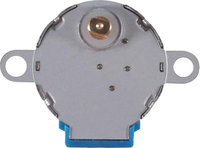
28BYJ-48 Stepper Motor
The 28BYJ-48 is a 5-wire uni-polar stepper motor that runs on 5 or 12 volts. The interesting thing about this motor is that people have been using it in countless applications over the last few decades. It is used in air-conditioner, vending machines and many other applications. One of the best things about these motors is that they can be positioned accurately, one ‘step’ at a time. The other advantage is that they are relatively precise in their movement and they are quite reliable since the motor does not use contact brushes.
Specifications
| Rated voltage | 5 V or 12 V |
| Coil Resistance | 50 Ohms |
| Coil Type | Unipolar |
| Diameter – shaft | 0.197″ (5.00 mm) |
| Length – shaft and bearing | 0.394″ (10 mm) |
| Features | Flatted shaft |
| Size/dimension | Round – 1.100″ dia (28.00 mm) |
| Mounting hole spacing | Flatted Shaft |
| Gear reduction | 1/64 (see note) |
| Step angle | Half step mode (Recommended): 0.0879° |
| Full step mode: 0.176° | |
| Steps per revolution | Half step mode: 4096 |
| Full step mode: 2048 | |
| Termination style | Wire leads with connector |
| Motor type | Permanent Magnet Gear Motor |
| Number of phases | 4 |
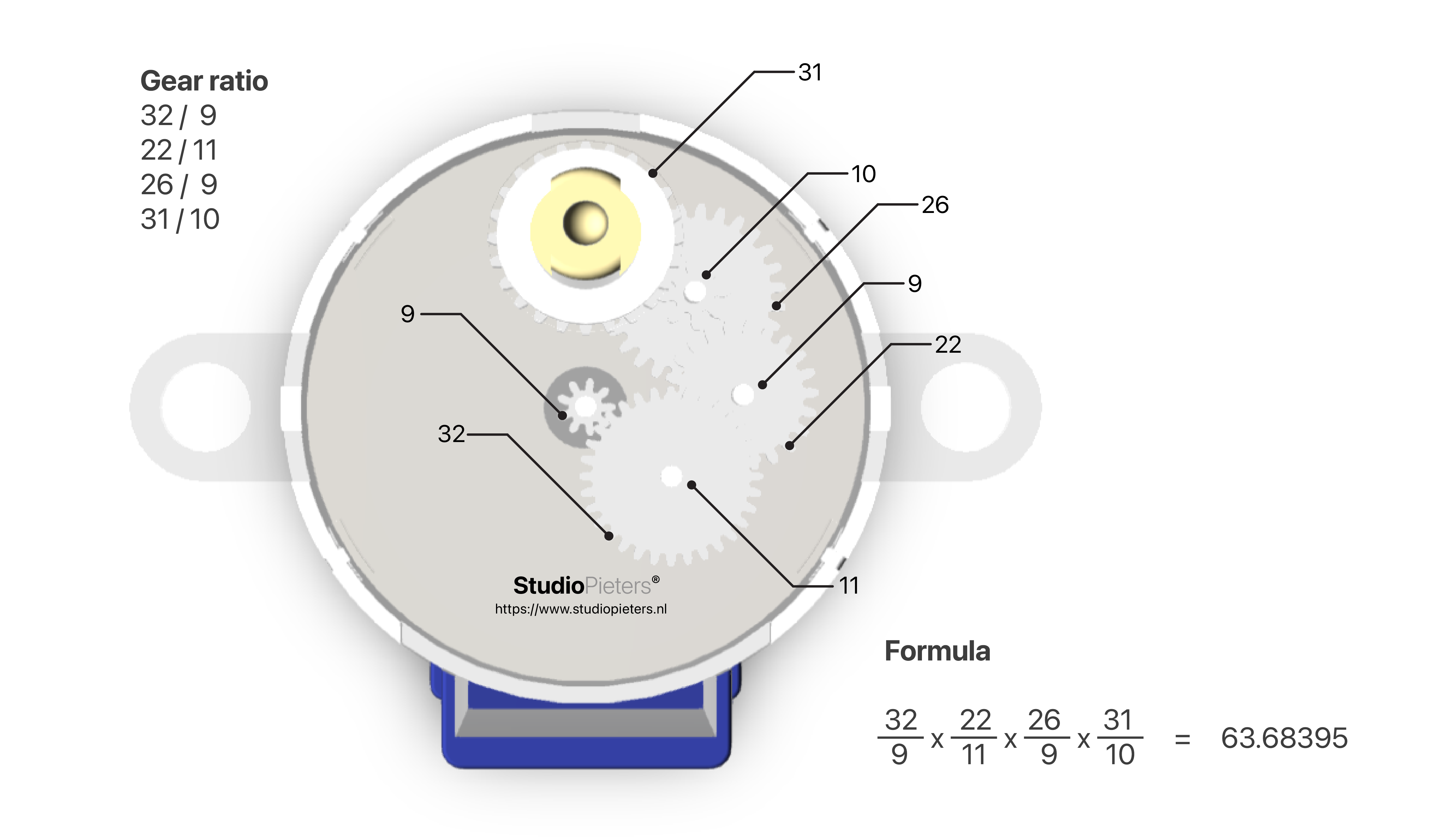
Gear Reduction Ratio
According to the data sheet, when the 28BYJ-48 motor runs in full step mode, each step corresponds to a rotation of 11.25°. That means there are 32 steps per revolution (360° / 11.25° = 32). In addition, the motor has a 1 / 64 reduction gear set. (Actually its 1 / 63.68395 but for most purposes 1/64 is a good enough approximation) What this means is that there are actually 32 *63.68395 steps per revolution = 2037.8864 ~ 2038 steps! I am not sure if all manufacturers use the exact same gearbox, but you can just adjust the steps per revolution in the code, to match your model.
Power Consumption
The power consumption of the motor is around 240mA. Because the motor draws too much power, it is best to power it directly from an external 5V or 12V power supply rather than drawing that power from a micro-controller.

ULN2003 Driver Board
The motor usually comes with a ULN2003 based driver board. The ULN2003 is one of the most common motor driver IC’s, consisting of an array of 7 Darlington transistor pairs, each pair is capable of driving loads of up to 500mA and 50V. Four out of seven pairs are used on this board. The board has a connector that mates the motor wires perfectly which makes it very easy to connect the motor to the board. There are also connections for four control inputs as well as power supply connections. The board has four LED’s that show activity on the four control input lines (to indicate stepping state). They provide a nice visual when stepping.
Torque
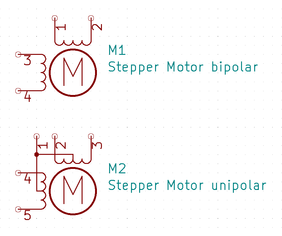
Now this kind of motor is not really up-to-date with modern technology. Uni-polar stepper motors are not that common anymore. Bipolar steppers are twice as efficient with the same amount of copper on the internal windings. Even in full stepping mode, a uni-polar stepper still has 2 out of four wires not active all the time. So basically, if there was a way to run current through all windings in the motor at all times, the thing would be stronger and faster.
That’s what happens in a bipolar stepper motor. It has only two windings instead of four in a uni-polar stepper. Both windings can be activated all the time, but their polarity is switched in four steps. This means that this kind of motor only has four wires instead of 5 (or 6 or 8).
The tricky part is changing the polarity. That cannot be achieved by the simple driver board that came with this motor. It only activates one or two out of four outputs, but current always flows in one direction.
What if we could change the wiring of this motor, thus converting it to a bipolar model? All you would need to do is cut the red wire in the scheme above and then ignore the center connection marked as 1. The result would be a bipolar stepper motor!
Modification
I found out that this is very easy with this motor. All you need is a sharp knife and a tiny screwdriver. Use the latter to remove the blue plastic cap that hides a small PCB. On this PCB, you can see eleven solder points. All it does is fixate the wiring of this stepper (which can be either uni-polar or bipolar by design) into a uni-polar type by connecting the center of the two windings. If we cut this connection and ignore it in our scheme, what’s left is a real bipolar stepper motor.
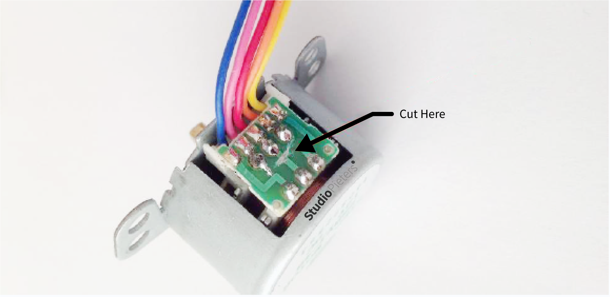
This is what the PCB looks like in detail. The red connection in the scheme above is actually the copper connection in this picture that I cut with a cutter knife. That’s all you need to do! Well, for your own peace of mind, you could also try to re-attach the blue plastic cover. And now, ignore the red wire of the motor. We don’t need it anymore.

REFERENCE
Digikey,28BYJ-48 Datasheet (2021), 28BYJ-48 – 5V Stepper Motor ,https://www.digikey.nl/nl/datasheets/mikroelektronika/mikroelektronika-step-motor-5v-28byj48-datasheet LastMinuteEngineers, 28BYJ-48 (2021), Control 28BYJ-48 Stepper Motor with ULN2003 Driver & Arduino, https://lastminuteengineers.com/28byj48-stepper-motor-arduino-tutorial Jangeox’ blog, 28BYJ-48 (2013), Change unipolar 28BYJ-48 to bipolar stepper motor, http://www.jangeox.be/2013/10/change-unipolar-28byj-48-to-bipolar.html