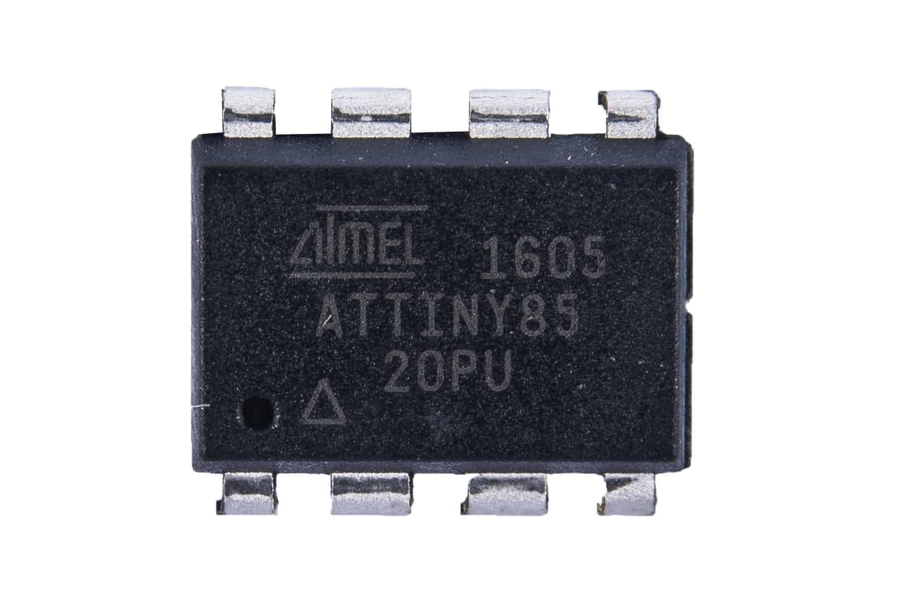
In one of my previous posts (ATTiny85), I detailed an ATTiny85, or in my case the ATTiny85 SMD chip. These chips are al the same only the package is different. In this blog I will use a ATTiny that is breadboard friendly in combination with a I2C OLED.
I2C OLED
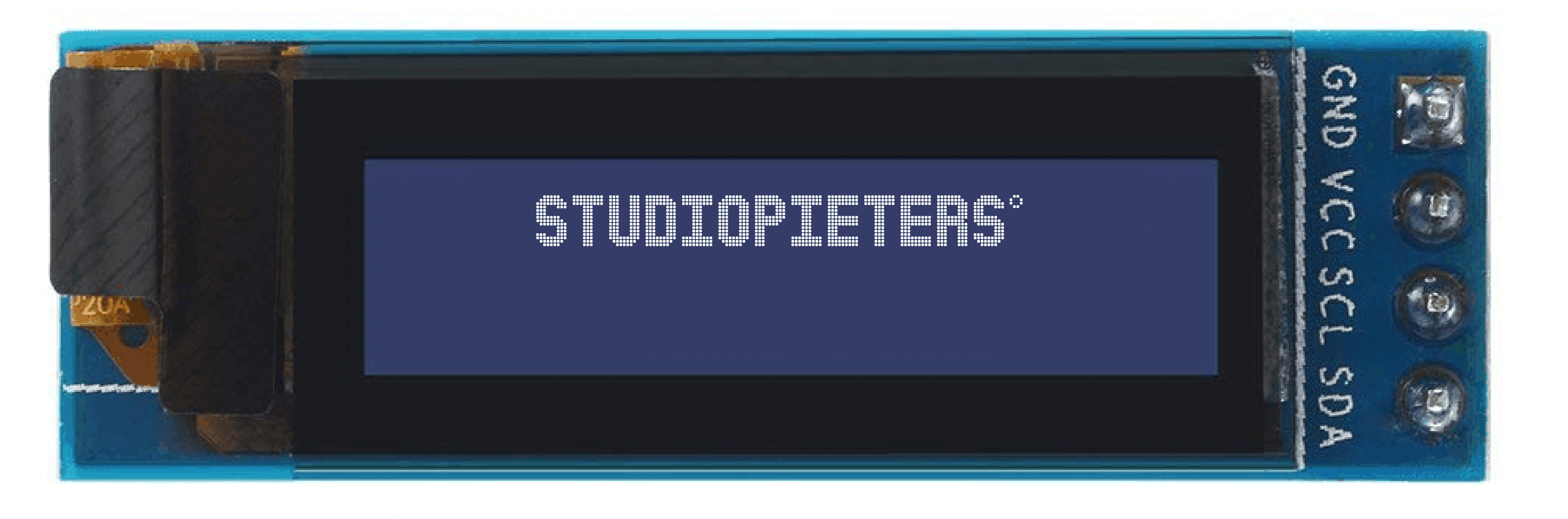
OLED 0.91 inch is a monochrome graphic display module with a built-in 0.91 inch, 128X32 high-resolution display. The OLED 0.91 inch is able to work despite the absence of back-light. In a dark environment, the contrast of OLED display is higher than LCD display. This device is I2C or SPI compatible. Due to its capability in displaying, it is often used in various application for instances, smart watch, MP3, function cellphone, portable health device and many others.
Note: I bought mine OLED display here
I2C OLED Specifications
OLED display, no need back light, self-illumination, The display performance is better than the traditional LCD display, also lower power consumption. It’s Driver IC is a SSD1306 and the Size is a 0.91 inch OLED with a resolution of 128 x 32 pixels. It has a IIC interface and the display Color can be white or blue.
I2C OLED pins
GND: Power Ground
VCC: Power + (DC 3.3 ~5v)
SCL: Clock Line
SDA: Data Line
connect a I2C OLED to a ATTiny85
I want to find out how to connect a ATTiny85 to I2C OLED Display. If you don’t know what a ATTiny is you can read about it here. I will use a Arduino Board as ISP (You may use the Arduino board of your choice, but you need to take note of the pins used for your board when using it as an ISP.) Then we need A ATTiny85 integrated chip. An I2C OLED display in my case, I am using the Oled display 0.91Inch I2C 3,3V-5V. some Jumper wires and a Breadboard. Here you will find the ATtiny85 pin-out, and read further how to connect this to the Arduino board to upload sketches from it to the ATtiny85 integrated chip.

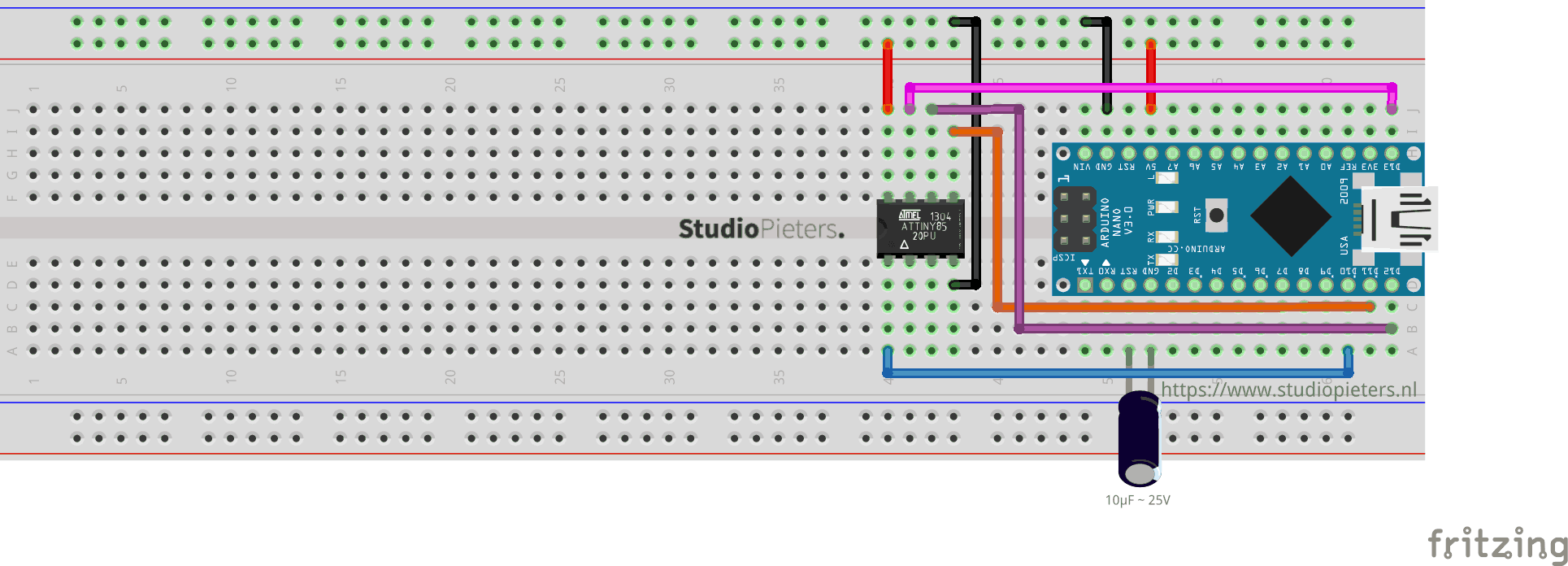
ARDUINO TO ATTINY85 CONNECTIONS
Connect the following (I am using an Arduino Nano, so you have to take note the necessary pins of the board you are using when using it as an ISP).
| Arduino Nano | ATTINY85 | |
| MOSI | Digital Pin 11 | PB0 (Chip Pin 5) |
| MISO | Digital Pin 12 | PB1 (Chip Pin 6) |
| SCL | Digital Pin 13 | PB2 (Chip Pin 7) |
| RESET | Digital Pin 10 | PB5 (Chip Pin 1) |
| VCC | VCC (5V) | VCC (Chip Pin 8) |
| GND | GND | GND (Any GND pin) |
Note: I bought my Arduino Nano here and the Attiny85 here
ARDUINO AS a programmer / ISP.
In my previous blog here. You can find how to setup a Arduino as a Programmer / ISP. Once you have followed these steps you can add the required library.
Update 19-08-2020: you can use this library: http://drazzy.com/package_drazzy.com_index.json
ADDING THE REQUIRED LIBRARY
Now we need to install the required library. But first I need a library that is small enough for my ATTiny85. Using Google I found Tiny4kOLED library here. To get this Library working you need a prerequisite library called TinyWireM.h. You can find this one here. Install these two library’s into your Arduino IDE software.
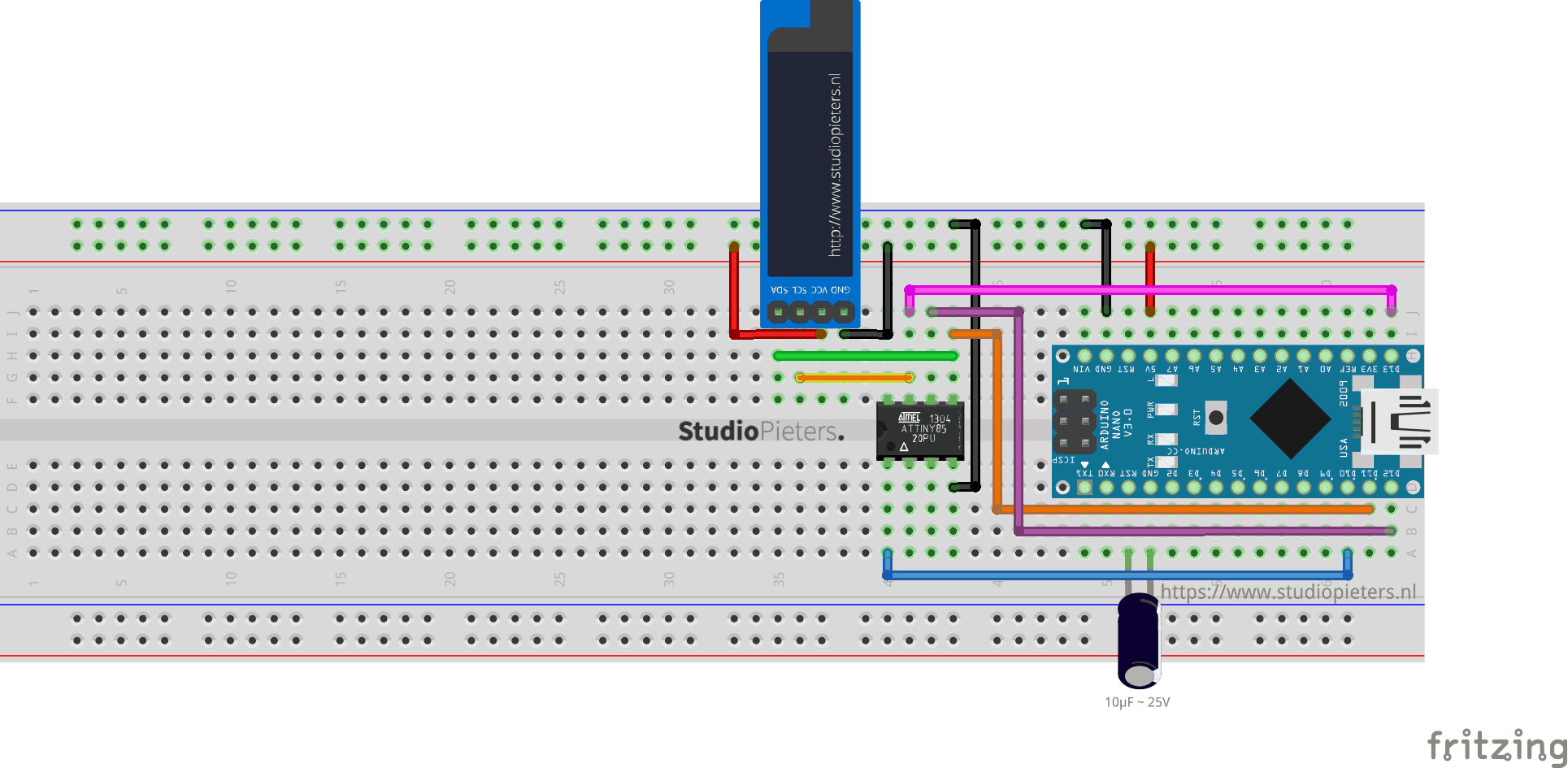
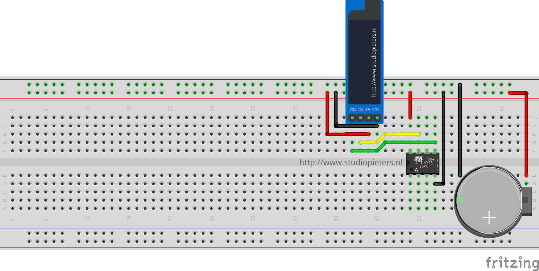
connect the I2C OLED display to the ATtiny85
Since our OLED display is using I2C, we only need 4 pins. VCC, GND, SCL and SDA. From the ATtiny85 pin-out, you will see VCC (chip pin 8), GND (chip pin 4), SCL (chip pin 7, PB2) and SDA (chip pin 5, PB0). Connect the corresponding pins for these two modules.
| ATTINY85 | I2C OLED |
| PB2 (Chip Pin 7) | SCL Pin (yellow wire) |
| PB0 (Chip Pin 5) | SDA Pin (Green Wire) |
| VCC (Chip Pin 8) | VCC (Red Wire) |
| GND (Chip Pin 4) | GND (Black wire) |
UPLOADING SKETCH TO ATTINY85
Make sure that the connections are as stated as described here above. Open the program / sketch you want uploaded to your ATtiny85.
Go to Tool and setup the following.
| Board: | “ATtiny25/45/85” |
| Processor: | “ATtiny85” |
| Clock: | “Internal 8 MHz” |
| Port: | Select the port where your board is connected to. |
Upload your desired sketch to your ATtiny85 (or your preferred board) by going to Sketch > Upload Using Programmer.
The sketch should be uploading to your ATtiny85 at this stage.
The Code
/* Project name: ATTiny85 - OLED (I2C)
    Project URI: https://www.studiopieters.nl/attiny85-oled-i2c
    Description: ATTiny85 - OLED (I2C)
    Version: 2.0.9
    License: MIT
*/

#include <Tiny4kOLED.h>

void setup() {

  // Send the initialization sequence to the oled. This leaves the display turned off
  oled.begin();
  // Clear the memory before turning on the display
  oled.clear();
  // Turn on the display
  oled.on();
  // Switch the half of RAM that we are writing to, to be the half that is non currently displayed
  oled.switchRenderFrame();
}

void loop() {

  /* -----------------------------------------
     Show screen with two different font sizes
     -----------------------------------------
  */

  // Clear the non-displayed half of the memory to all black
  // (The previous clear only cleared the other half of RAM)
  oled.clear();

  // The characters in the 8x16 font are 8 pixels wide and 16 pixels tall
  // 2 lines of 16 characters exactly fills 128x32
  oled.setFont(FONT8X16);

  // Position the cusror
  // usage: oled.setCursor(X IN PIXELS, Y IN ROWS OF 8 PIXELS STARTING WITH 0);
  oled.setCursor(12, 0);

  // Write the text to oled RAM (which is not currently being displayed)
  // Wrap strings in F() to save RAM!
  oled.print(F("StudioPieters"));

  // The characters in the 6x8 font are 6 pixels wide and 8 pixels tall
  // 4 lines of 21 characters only fills 126x32
  oled.setFont(FONT6X8);

  // Position the cusror
  // Two rows down because the 8x16 font used for the last text takes two rows of 8 pixels
  oled.setCursor(1, 2);

  // Write the text to oled RAM (which is not currently being displayed)
  oled.print(F("ATTiny85 - OLED (I2C)"));

  // Position the cusror
  // Cursor X is in pixels, and does not need to be a multiple of the font width
  oled.setCursor(44, 3);

  // Write the text to oled RAM (which is not currently being displayed)
  oled.print(F("Project"));

  // Swap which half of RAM is being written to, and which half is being displayed
  oled.switchFrame();

  delay(3000);
I removed the wires connecting the Arduino Nano and the ATTiny85 and powered the module with a CR3230 Battery. Power the I2C OLED from ATtiny85’s 5V pin and GND pin.
YES IT WORKS!
DOWNLOAD ALL FILES FOR THIS PROJECT ON GITHUB.

DO YOU HAVE ANY QUESTIONS? LEAVE A COMMENT DOWN HERE.
REFERENCES
Tiny4kOLED, (20 jan 2018), Library for an ATTiny85 to use an SSD1306 powered, double buffered, 128×32 pixel OLED, over I2C, https://www.arduino.cc/en/Tutorial/ArduinoISP