I’m currently working on a project that requires a cheap, low-power micro-controller that’s programmable through Arduino and has a few more pins than the “standard” ATtiny85 micro-controller. That’s where I found the ATtiny84 and the ATtiny2313. It has many of the same features as the ATtiny85, but has 12 I/O pins / 18 I/O pins instead of six. But now we have to program these new additions. But first let’s have a look at the differences between these three options.

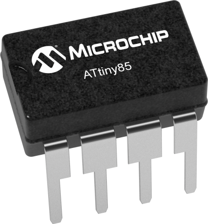
ATTiny 25 / 45 / 85 Chip
The high-performance, low-power Microchip 8-bit AVR RISC-based micro-controller combines 8KB ISP flash memory, 512B EEPROM, 512-Byte SRAM, 6 general purpose I/O lines, 32 general purpose working registers, one 8-bit timer/counter with compare modes, one 8-bit high speed timer/counter, USI, internal and external Interrupts, 4-channel 10-bit A/D converter, programmable watchdog timer with internal oscillator, three software select-able power saving modes, and debugWIRE for on-chip debugging. The device achieves a throughput of 20 MIPS at 20 MHz and operates between 2.7-5.5 volts.
By executing powerful instructions in a single clock cycle, the device achieves throughput’s approaching 1 MIPS per MHz, balancing power consumption and processing speed.
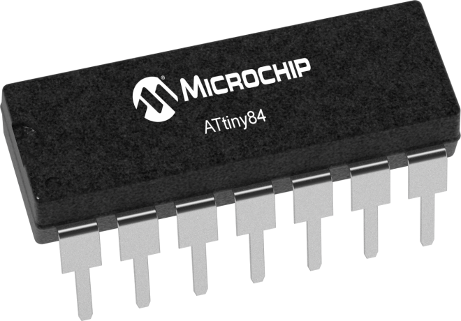
ATTiny 24 / 44 / 84 Chip
The high-performance, Microchip’s picoPower® 8-bit AVR® RISC-based micro-controller combines 8KB ISP flash memory, 512-Byte EEPROM, 512-Byte SRAM, 12 general purpose I/O lines, 32 general purpose working registers, an 2 timers/counters (8-bit/16-bit) with two PWM channels each, internal and external interrupts, 8-channel 10-bit A/D converter, programmable gain stage (1x, 20x) for 12 differential ADC channel pairs, programmable watchdog timer with internal oscillator, internal calibrated oscillator, and four software select-able power saving modes. The device operates between 1.8-5.5 volts.
By executing powerful instructions in a single clock cycle, the device achieves throughput’s approaching 1 MIPS per MHz, balancing power consumption and processor speed.
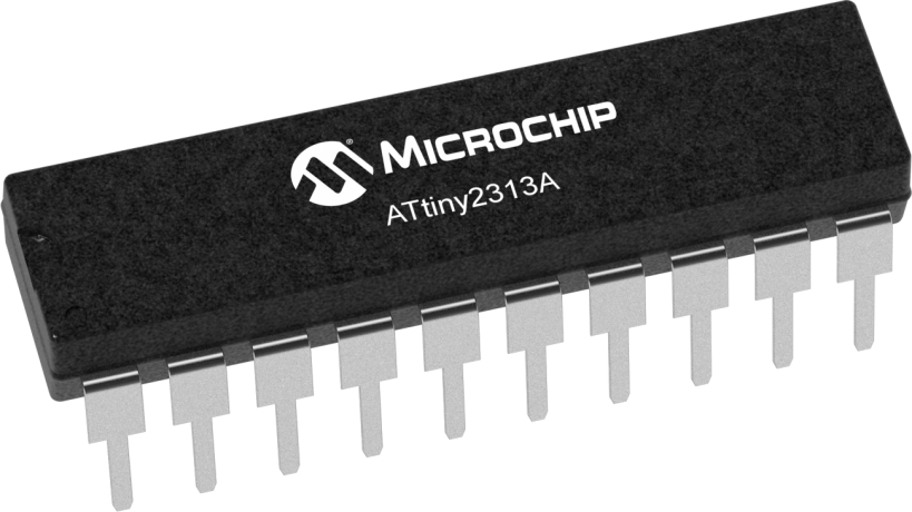
ATTiny 2313 / 4313 Chip
The high-performance Microchip picoPower AVR RISC-based CMOS 8-bit micro-controller combines 2KB flash memory, 128B EEPROM, 128B SRAM, 18 general purpose I/O lines, 32 general purpose working registers, a single-wire Interface for on-chip debugging, two flexible timer/counters with compare modes, internal and external interrupts, serial programmable USART, a universal serial interface (USI) with start condition detector, programmable watchdog timer with internal oscillator, and three software select-able power saving modes. The device operates between 1.8-5.5 volts.
By executing powerful instructions in a single clock cycle, the device achieves throughput’s approaching 1 MIPS per MHz, balancing power consumption and processing speed.
Programming the ATtiny’s
As it turns out, a lot of work has already been done to program ATtiny micro-controllers from Arduino, which makes this pretty easy. To start, connect an Arduino (Nano etc.) to the ATtiny 84 / 1313 using the Arduino as ISP configuration. I’ll be using a 3.3V Arduino Nano to keep everything nice and tidy on a breadboard. Connect the Arduino to your computer, open the Arduino IDE and select File > Examples > 11.ArduinoISP > ArduinoISP.
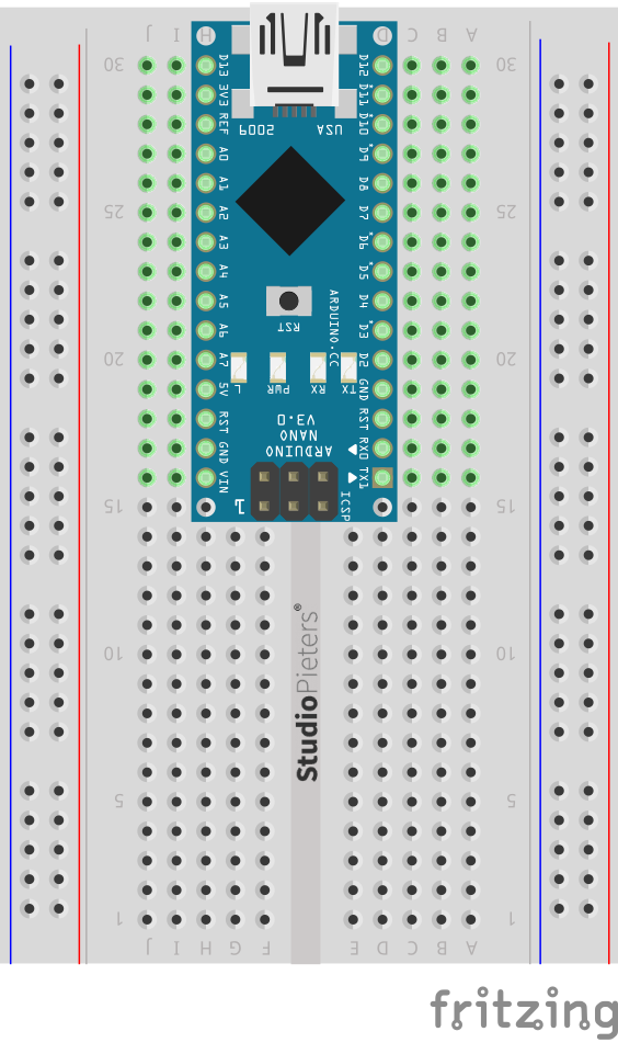
Select your Board from Tools (Arduino Nano in this case), choose the serial port and upload the ISP sketch to the Arduino. Note that in this first step, we’re programming the Arduino to act as an in-system programmer (ISP), which we’ll use to send compiled programs to our target micro-controller (ATtiny 84 / 2313 ).
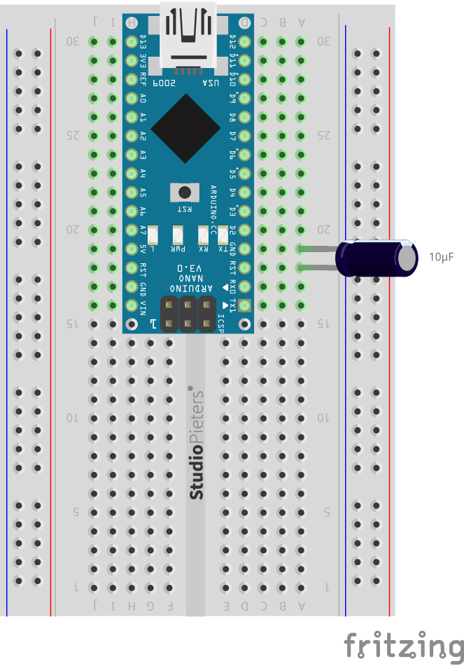
Once you have uploaded the ISP sketch, place a 10μF capacitor across RESET and GND of the Arduino board (watch the polarity – for electrolytic and tantalum capacitors, make sure the side with negative markings, “-“, is connected to GND). Many Arduino boards are configured to reset when avrdude (the tool that Arduino uses to upload code to Atmel AVR micro-controllers) begins communication across the serial line. We can prevent that from happening by adding the capacitor.
At this point, we have the Arduino configured as a programmer for the ATtiny.
ARDUINO NANO TO ATTINY CONNECTIONS
Let’s connect the necessary pins together. We need to connect the MOSI, MISO and SCK pins of both boards together (refer to the IC pin out), and Digital Pin 10 of the Arduino Nano to the ATtiny.
Connect the following (I am using an Arduino Nano, so you have to take note the necessary pins of the board you are using when using it as an ISP).
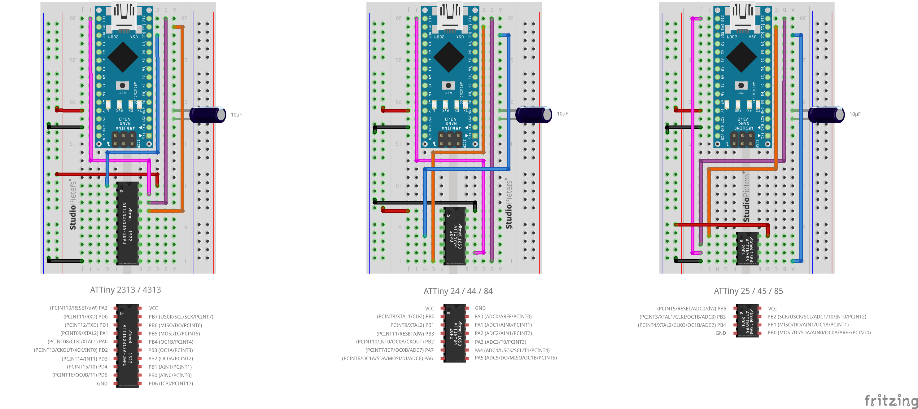
| Arduino Nano | ATTINY 25 / 45 / 85 | ATTINY 24 / 44 / 84 |
ATTINY 2313 / 4313 |
|
| MOSI | Digital Pin 11 | PB0 (Chip Pin 5) | PA6 (Chip Pin 7) | PB 5 (Chip Pin 17) |
| MISO | Digital Pin 12 | PB1 (Chip Pin 6) | PA5 (Chip Pin 8) | PB 6 (Chip Pin 18) |
| SCL | Digital Pin 13 | PB2 (Chip Pin 7) | PA4 (Chip Pin 9) | PB 7 (Chip Pin 19) |
| RESET | Digital Pin 10 | PB5 (Chip Pin 1) | PB3 (Chip Pin 4) | PA 2 (Chip Pin 1) |
| VCC | VCC (5V) | VCC (Chip Pin 8) | VCC (Chip Pin 1) | VCC (Chip Pin 20) |
| GND | GND | GND (GND pin 4) | GND (GND pin 14) | GND (GND pin10) |

INSTALLING THE ATTINY BOARDS
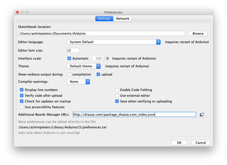
Open the Arduino IDE Software then go to Arduino > Preferences. You will see Additional Boards Manager URLs. Add this link there, by pressing the rightmost icon. and ad this link: http://drazzy.com/package_drazzy.com_index.json
http://drazzy.com/package_drazzy.com_index.json
Press OK (then another OK to exit from Preferences).
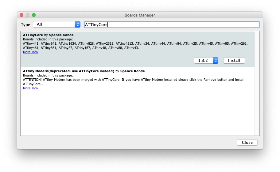
Now, go to Tools > Board > Boards Manager. Type attiny in the search field, and you should see ATTinyCore Spende Konde. Click it (ATTinyCore Spende Konde) and install the board. Now, you should see attiny boards from the list when you go to Tool > Boards. Scroll down to verify that the board is indeed installed.
ARDUINO AS ISP
Attach the Arduino Nano to your computer. Go to File > Examples > ArduinoISP, and click on Arduino ISP. Then go to Tools > Boards and select Arduino Nano (or your preferred board). Go to Tools > Port and select the port where your board is connected to. Upload the ArduinoISP sketch to your Arduino Nano (or your preferred board) by going to Sketch > Upload. At this stage, your Arduino Nano is ready to be used as a programmer.
Note: In some cases you need to select Processor : “ATMega328P (Old Bootloader)”
UPLOADING SKETCH TO ATTINY85 DEVELOPMENT BOARD
Make sure that the connections are as stated as described here above. Open the program / sketch you want uploaded to your ATtiny. Go to Tool and setup the following.
| Board: | “ATtiny24/44/84” | “ATtiny2313/3413” |
| Processor: | “ATtiny84” | “ATtiny2313” |
| Clock: | “Internal 8 MHz” | “Internal 8 MHz” |
| Port: | Select the port where your board is connected to. | Select the port where your board is connected to. |
Then make sure Arduino as ISP is selected under Tools -> Programmer. By default the ATtiny85 runs at 1MHz. To make it to run at 8MHz select Tools -> Burn Bootloader.

That’s it your done. you can now program your ATtiny!
DO YOU HAVE ANY QUESTIONS? LEAVE A COMMENT DOWN HERE.
REFERENCES
Spence Konde. (2019),Arduino core for ATtiny 1634, 828, x313, x4, x41, x5, x61, x7 and x8 , https://github.com/SpenceKonde/ATTinyCore