I need a remote that I can program and that will work on batteries for a long time. So I was thinking of using a ATTINY with a way that enables me to send the information over the air. And when it comes down to having inexpensive yet reliable 2-way RF solutions, In my previous blog I looked into a nRF24L01+ transceiver module from Nordic Semiconductor. In this blog I will have a look at the 433MHz RF Transmitter and Receiver Module.

Hardware Overview
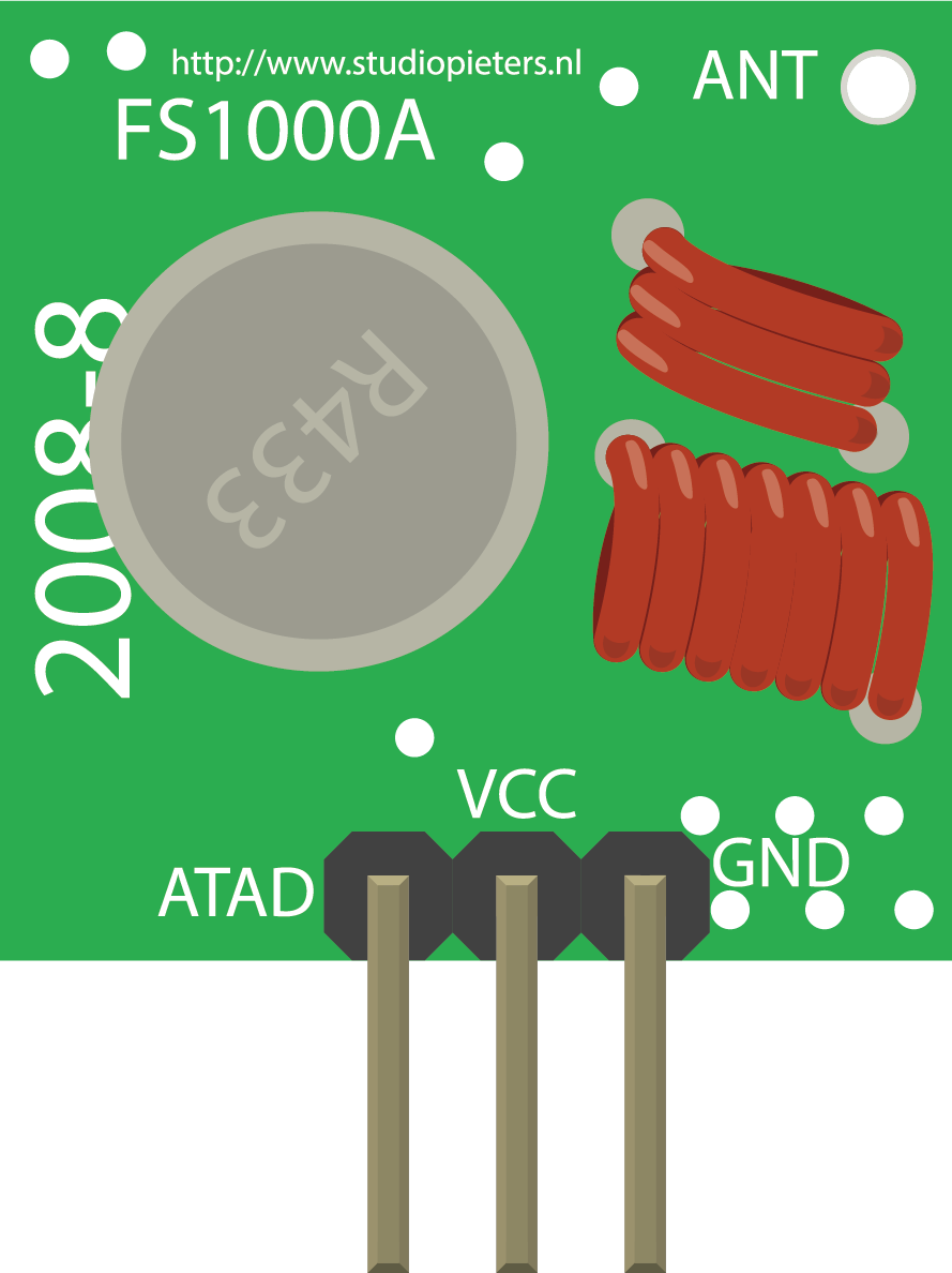
Let’s have a closer look at the 433MHz RF Transmitter (FS1000A) and Receiver (XD-RF-5V) Modules. This little module is a transmitter among two. It is really simple as it looks. The heart of the module is the SAW resonator which is tuned for 433.xx MHz operation. There is a switching transistor and a few passive components, that’s it. When a logic HIGH is applied to the DATA input, the oscillator runs producing a constant RF output carrier wave at 433.xx MHz and when the DATA input is taken to logic LOW, the oscillator stops. This technique is known as Amplitude Shift Keying, which we will discuss in detail shortly.
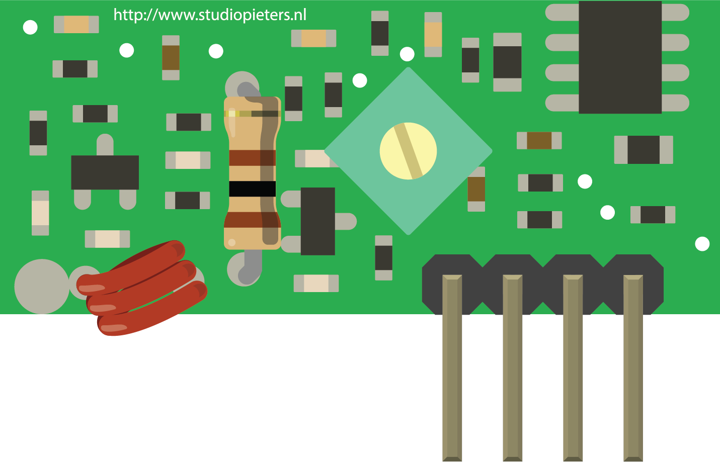
This one is a receiver module. Though it looks complex, it is as simple as the transmitter module. It consists of a RF tuned circuit and a couple of OP Amps to amplify the received carrier wave from the transmitter. The amplified signal is further fed to a PLL (Phase Lock Loop) which enables the decoder to “lock” onto a stream of digital bits which gives better decoded output and noise immunity.
ASK – Amplitude Shift Keying
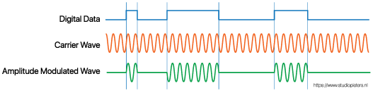
As discussed above, for sending the digital data over radio, these modules use a technique called Amplitude Shift Keying or ASK. In Amplitude Shift Keying the amplitude (i.e. the level) of the carrier wave (in our case it’s a 433MHz signal) is changed in response to the incoming data signal.
This is very similar to the analog technique of amplitude modulation which you might be familiar with if you’re familiar with AM radio. It’s sometimes called binary amplitude shift keying because there are only two levels we are concerned with. You can think of it as an ON/OFF switch.
- For Digital 1 – This drives the carrier at full strength.
- For Digital 0 – This cuts the carrier off completely.
This is how the Amplitude modulation looks like:
Amplitude Shift keying has the advantage of being very simple to implement. It is quite simple to design the decoder circuitry. Also ASK needs less bandwidth than other modulation techniques like FSK (Frequency Shift Keying). This is one of the reasons for being inexpensive.The disadvantage however is that ASK is susceptible to interference from other radio devices and background noise. But as long as you keep your data transmission to a relatively slow speed it can work reliably in most environments.
433MHz RF Transmitter & Receiver Pinout
Let’s have a look at the pinout of 433MHz RF Transmitter and Receiver Modules.
- DATA pin accepts digital data to be transmitted.
- VCC supplies power for the transmitter. This can be any positive DC voltage between 3.5V to 12V. Note that the RF output is proportional to the supply voltage i.e. the higher the Voltage, the greater the range will be.
- GND is a ground pin.
- Antenna is a pin for external antenna. As discussed earlier, you will want to solder a 17.3 cm piece of solid wire to this pin for the improved range.
- VCC supplies power for the receiver. Unlike the transmitter, supply voltage for receiver needs to be 5V and is the left pin.
- DATA pins output the digital data received. The two center pins are internally tied together, so you can use either one for data out.
- GND is a ground pin and is the right Pin.
- Antenna is a pin for external antenna which is often unmarked. It is the pad in the lower left of the module, right next to the small coil. Again, you will want to solder a 17.3 cm piece of solid wire to this pin for the improved range.
Note: As you can see, the voltage is on the high side, which means that they are not suitable for my purpose. Nevertheless, I will continue with testing, because these modules are of course suitable for a number of other projects!
Wiring – Connecting 433MHz RF Transmitter and Receiver to Arduino Nano
Now that we know everything about the modules it is time to put them to use!
As we will be sending data between two Arduino nano boards, we will of course need two Arduino nano boards, two breadboards and a couple of jumper wires.
The wiring for the transmitter is fairly simple. It has only three connections. Connect the VCC pin to 5V pin and GND to ground on the Arduino. The Data-In pin should be connected to Arduino’s digital pin #12. You should try and use pin 12 as by default the library we’ll be using in our sketch uses this pin for data input. The following illustration shows the wiring.
![]()
Once you have the transmitter wired you can move on to the receiver. The wiring for the receiver is just as easy as the transmitter was.
Once again there are only three connections to make. Connect the VCC pin to 5V pin and GND to ground on the Arduino. Any of the middle two Data-Out pins should be connected to digital pin #11 on the Arduino. This is how wiring for the receiver should look like.
![]()
Now that both the transmitter and receiver are wired up we will need to write some code and send it to the respective Arduino boards. Since you probably have only one PC, we will start with the transmitter. Once the code has been loaded there, we’ll move on to the receiver. The Arduino to which transmitter is connected can then be powered using a power supply or battery.
RadioHead Library – a Swiss Army Knife for wireless modules
Before we start coding, there is a library called RadioHead we will need to install into our Arduino IDE that will make writing the code a lot simpler. RadioHead is a library that allows simple data transfer between Arduino boards. It’s so versatile that it can be used to drive all sorts of radio communications devices, including our 433MHz modules.
What RadioHead library does is to take our data, encapsulate it into a packet of data which includes a CRC (Cyclic Redundancy Check) and then send it with the necessary preamble and header to another Arduino. If the data is received correctly, the receiving Arduino is informed that there is data available and proceeds to decode and action it. The RadioHead Packet is made up as follows: A 36 bit stream of “1” and “0” bit pairs, called a “Training Preamble”, is sent at the start of every transmission. These bits are necessary for the receiver to adjust its gain prior to getting the actual data. Followed by this, a 12 bit “Start Symbol” and then the actual data (payload) is added.
A Frame Check Sequence or CRC is added at the end of the packet which is recalculated by RadioHead at the receiver end and if the CRC check is correct, the receiving device is alerted. If the CRC check fails, the packet is discarded.
The whole packet looks something like this:
| 36bits | 12bits | 8bits | 16bits |
| Training Preamble | Start Symbol | Meassage length | Frame Check Sequence |
You can download the library, by visiting the airspayce.com or, just click this here to download.
To install it, open the Arduino IDE, go to Sketch – Include Library – Add .ZIP Library, and then select the RF24-master file that you just downloaded. If you need more details on installing a library, visit this Installing an Arduino Library tutorial.
Arduino Code – For 433MHz RF Transmitter
In our experiment we will just send a simple text message from the transmitter to the receiver. It will be helpful to understand how to use the modules and can serve as the basis for more practical experiments and projects.
Here is the sketch we will be using for our transmitter:
// Include RadioHead Amplitude Shift Keying Library
#include <RH_ASK.h>
// Include dependant SPI Library
#include <SPI.h>

// Create Amplitude Shift Keying Object
RH_ASK rf_driver;

void setup()
{
  // Initialize ASK Object
  rf_driver.init();
}

void loop()
{
  const char *msg = "Hello World";
  rf_driver.send((uint8_t *)msg, strlen(msg));
  rf_driver.waitPacketSent();
  delay(1000);
}
It’s a pretty short sketch but it’s all you need to get a signal transmitted. The sketch starts by including RadioHead ASK library. We also need to include the Arduino SPI Library as the RadioHead library is dependent on it.Next, we need to create an ASK object in order to access special functions related to RadioHead ASK library. In setup function, we need to initialize the ASK object. In loop function, we start by preparing a message. It’s a simple text string and stored in a character pointer named msg. Keep in mind that, your message can be anything but should not exceed 27 characters for better performance. And be sure to count the number of characters in it, as you will need that count in the receiver code. In our case, we have 11 characters.
The message is then transmitted using a send() function. It has two parameters: first is array of data and second is number of bytes (length of the data) to be sent. The send() function is usually followed by waitPacketSent() function which waits until any previous transmit packet is finished being transmitted. After that the sketch waits for a second to give our receiver time to take in everything.
Arduino Code – For 433MHz RF Receive
In our experiment we will just send a simple text message from the transmitter to the receiver. It will be helpful to understand how to use the modules and can serve as the basis for more practical experiments and projects.
Here is the sketch we will be using for our transmitter:
// Include RadioHead Amplitude Shift Keying Library
#include <RH_ASK.h>
// Include dependant SPI Library
#include <SPI.h>

// Create Amplitude Shift Keying Object
RH_ASK rf_driver;

void setup()
{
  // Initialize ASK Object
  rf_driver.init();
  // Setup Serial Monitor
  Serial.begin(9600);
}

void loop()
{
  // Set buffer to size of expected message
  uint8_t buf[11];
  uint8_t buflen = sizeof(buf);
  // Check if received packet is correct size
  if (rf_driver.recv(buf, &buflen))
  {

    // Message received with valid checksum
    Serial.print("Message Received: ");
    Serial.println((char*)buf);
  }
}
Just like the transmitter case, receiver code starts by loading both the RadioHead and SPI libraries and creating an ASK object. In the setup function: we initialize the ASK object and also set up the serial monitor as this is how we will view our received message. In loop function: we create a buffer of size same as the transmitted message. In our case, it’s 11, remember? You will need to adjust this to match your message length. Be sure to include any spaces and punctuation as they all count as characters.

Next, we call a recv() function. This turns the receiver on if it not already on. If there is a valid message available, it copies the message to its first parameter buffer and return true else return false. If the function returns true, the sketch enters into if statement and prints the received message on the serial monitor. Then we go back to the start of the loop and do it all over again. After loading the sketch open your serial monitor. If all is OK you should see your message.
Improving range of 433MHz RF modules
The antenna that you use for both the transmitter and receiver can really affect the range you’ll be able to obtain with these RF modules. In fact without an antenna you’d be lucky to communicate over a distance of more than a meter. With a proper antenna design, you’ll be able to communicate over a distance of 50 meters. Of course that is outdoors in an open space. Your range indoors, especially through walls, will be slightly weakened. The antenna need not be complicated. A simple piece of single core wire can make an excellent antenna for both the transmitter and receiver. The antenna diameter hardly has any importance, as long as the length of the antenna is maintained.
The most effective antenna has the same length as the length of the wave it is used for. For practical purposes, half or a quarter of that length will suffice.
The wavelength of a frequency is calculated as
Wavelength of frequency = Speed of the transmission (v)
Transmission frequency (f)
In air, speed of transmission is equal to the speed of light, which is 299,792,458 m/s to be precise. So, For the 433 MHz band the wavelength is
Wavelength of frequency = 299,792,458 m/s
433,000,000 Hz
= 0.6924 meters
= 69.24 cm
As full wave 69.24 cm antenna is a pretty long antenna, it is not very practical to use. That’s why we’ll opt for a quarter wave antenna which works out to about 17.3 cm or 6.8 inches.
Just in case, if you are experimenting with other radio transmitters that use different frequencies, you can use the same formula to calculate the required antenna length. Pretty easy, Right?
Note: Even a 17.3 cm antenna can seem inconvenient in your tiny Arduino project. But Do NOT be tempted to coil the antenna to make it more compact as this will seriously impact range. A straight antenna is always best!

REFERENCE
lastminuteengineers, 433mhz-rf-wireless-arduino-tutorial (2019), How 433MHz RF Tx-Rx Modules Work & Interface with Arduino, https://lastminuteengineers.com