I need a remote that I can program and that will work on batteries for a long time. So I was thinking of using a ATTINY with a way that enables me to send the information over the air. And when it comes down to having inexpensive yet reliable 2-way RF solutions, no one does a better job than nRF24L01+ transceiver module from Nordic Semiconductor.

Hardware Overview
Radio Frequency
The nRF24L01+ transceiver module is designed to operate in 2.4 GHz worldwide ISM frequency band and uses GFSK modulation for data transmission. The data transfer rate can be one of 250kbps, 1Mbps and 2Mbps.
What is 2.4 GHz ISM band?
2.4 GHz band is one of the Industrial, Scientific, and Medical (ISM) bands reserved internationally for the use of unlicensed low-powered devices. Examples are Cordless phones, Bluetooth devices, near field communication (NFC) devices, and wireless computer networks (WiFi) all use the ISM frequencies.
Power consumption
The operating voltage of the module is from 1.9 to 3.6V, but the good news is that the logic pins are 5-volt tolerant, so we can easily connect it to an Arduino or any 5V logic micro-controller without using any logic level converter.
The module supports programmable output power viz. 0 dBm, -6 dBm, -12 dBm or -18 dBm and consumes unbelievably around 12 mA during transmission at 0 dBm, which is even lower than a single LED. And best of all, it consumes 26 µA in standby mode and 900 nA at power down mode. That’s why they’re the go-to wireless device for low-power applications.
SPI Interface
The nRF24L01+ transceiver module communicates over a 4-pin Serial Peripheral Interface (SPI) with a maximum data rate of 10Mbps. All the parameters such as frequency channel (125 selectable channels), output power (0 dBm, -6 dBm, -12 dBm or -18 dBm), and data rate (250kbps, 1Mbps, or 2Mbps) can be configured through SPI interface.
The SPI bus uses a concept of a Master and Slave, in most common applications our Arduino is the Master and the nRF24L01+ transceiver module is the Slave. Unlike the I2C bus the number of slaves on the SPI bus is limited, on the Arduino Uno you can use a maximum of two SPI slaves i.e. two nRF24L01+ transceiver modules.
Here are complete specifications:
| Frequency Range | 2.4 GHz ISM Band |
| Maximum Air Data Rate | 2 Mb/s |
| Modulation Format | GFSK |
| Max. Output Power | 0 dBm |
| Operating Supply Voltage | 1.9 V to 3.6 V |
| Max. Operating Current | 13.5mA |
| Min. Current(Standby Mode) | 26µA |
| Logic Inputs | 5V Tolerant |
| Communication Range | 800+ m (line of sight) |
Pin out
The NRF24L01 module works with the Arduino through the SPI communication. The pin out of the module is as follows
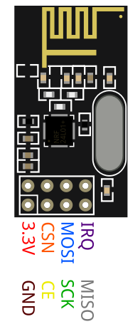
GND is the Ground Pin. It is usually marked by encasing the pin in a square so it can be used as a reference for identifying the other pins.
VCC supplies power for the module. This can be anywhere from 1.9 to 3.9 volts. You can connect it to 3.3V output from your Arduino. Remember connecting it to 5V pin will likely destroy your nRF24L01+ module!
CE (Chip Enable) is an active-HIGH pin. When selected the nRF24L01 will either transmit or receive, depending upon which mode it is currently in.
CSN (Chip Select Not) is an active-LOW pin and is normally kept HIGH. When this pin goes low, the nRF24L01 begins listening on its SPI port for data and processes it accordingly.
SCK (Serial Clock) accepts clock pulses provided by the SPI bus Master.
MOSI (Master Out Slave In) is SPI input to the nRF24L01.
MISO (Master In Slave Out) is SPI output from the nRF24L01.
IRQ is an interrupt pin that can alert the master when new data is available to process.
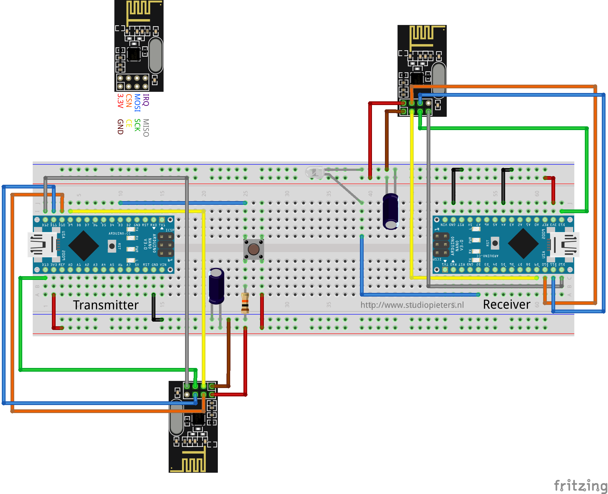
Wiring – Connecting nRF24L01+ transceiver module to Arduino NANO
Now that we have a complete understanding of how nRF24L01+ transceiver module works, we can begin hooking it up to our Arduino! To start with, connect VCC pin on the module to 3.3V on the Arduino and GND pin to ground. The pins CSN and CE can be connected to any digital pin on the Arduino. In our case, it’s connected to digital pin 9 and pin 10 respectively. Now we are remaining with the pins that are used for SPI communication.

As nRF24L01+ transceiver module require a lot of data transfer, they will give the best performance when connected up to the hardware SPI pins on a micro controller. The hardware SPI pins are much faster than ‘bit-banging’ the interface code using another set of pins. Note that each Arduino Board has different SPI pins which should be connected accordingly. For Arduino boards such as the NANO V3.0 those pins are digital 13 (SCK), 12 (MISO) and 11 (MOSI). Remember! You need to make two of these circuits. One acts as a transmitter and the other as a receiver. The wiring for both is identical.
RF24 Arduino Library for nRF24L01+ Module
Interfacing with nRF24L01+ transceiver module is a bunch of work, but luckily for us, there are a number of libraries available. One of the popular libraries is RF24. This library has been around for several years. It is simple to use for beginners, but yet offers a lot for advanced users. In our experiments, we will be using the same library. You can download the latest version of library on the RF24 GitHub repository fork or, just click this button to download the zip here.
To install it, open the Arduino IDE, go to Sketch – Include Library – Add .ZIP Library, and then select the RF24-master file that you just downloaded. If you need more details on installing a library, visit this Installing an Arduino Library tutorial.
Reduce Power Supply Noise
An RF circuit that generates a Radio Frequency (RF) signal, is very sensitive to power supply noise. If not controlled, the power supply noise can significantly reduce the range you can get. Unless the power source is a stand-alone battery, there is a good chance that there is noise associated with the generation of the power. To prevent this noise from entering the system, it is advised to place a 10 µf filter capacitor across the power supply line as physically close to the nRF24L01+ module as possible..
Change your channel frequency
Another potential source of noise for an RF circuit is the outside environment, especially if you have neighboring networks set on the same channel or interference from other electronics.To prevent these signals from causing issues, we suggest using the highest 25 channels your nRF24L01+ module. Reason for this is WiFi uses most of the lower channels.
radio.setChannel(125);
Lower Data Rate
The nRF24L01+ offers highest receiver sensitivity at 250Kbps speed which is -94dBm. However at 2MBps data rate, the receiver sensitivity drops to -82dBm. If you speak this language, you know that the receiver at 250Kbps is nearly 10 times more sensitive than at 2Mbps. That means the receiver can decode a signal that is 10 times weak.

What does Receiver (Rx) sensitivity mean?
Receiver sensitivity is the lowest power level at which the receiver can detect an RF signal. The larger the absolute value of the negative number, the better the receiver sensitivity. For example, a receiver sensitivity of −94 dBm is better than a receiver sensitivity of −82 dBm by 12 dB. So, lowering the data rate can significantly improve the range you can achieve. Also, for most of our projects, 250Kbps speed is more than sufficient.
Higher Output Power
Setting maximum output power can also improve the communication range. The nRF24L01+ lets you choose one of the output power viz. 0 dBm, -6 dBm, -12 dBm or -18 dBm. Selecting 0 dBm output power sends stronger signal over the air.
Code for Reciver And Transmitter.
#include <SPI.h>
#include "nRF24L01.h"
#include "RF24.h"
#include "printf.h"

// Set up nRF24L01 radio on SPI bus plus pins 9 & 10 (CE & CS)

RF24 radio(9, 10);

// sets the role of this unit in hardware.  Connect to GND to be the 'led' board receiver
// Don't connect to be the the 'remote' transmitter
const int role_pin = A4;

// Pins on the remote for buttons
const uint8_t button_pins[] = { 2, 3, 4, 5, 6, 7 };
const uint8_t num_button_pins = sizeof(button_pins);

// Pins on the LED board for LED's
const uint8_t led_pins[] = { 2, 3, 4, 5, 6, 7 };
const uint8_t num_led_pins = sizeof(led_pins);

// Single radio pipe address for the 2 nodes to communicate.
const uint64_t pipe = 0xE8E8F0F0E1LL;

typedef enum { role_remote = 1, role_led } role_e;

// The debug-friendly names of those roles
const char* role_friendly_name[] = { "invalid", "Remote", "LED Board"};

role_e role;

uint8_t button_states[num_button_pins];
uint8_t led_states[num_led_pins];

void setup(void)
{
  pinMode(role_pin, INPUT);
  digitalWrite(role_pin, HIGH);
  delay(20); // Just to get a solid reading on the role pin

  // read the address pin, establish our role
  if ( digitalRead(role_pin) )
    role = role_remote;
  else
    role = role_led;

  Serial.begin(115200);
  printf_begin();
  printf("\n\rRF24/examples/led_remote/\n\r");
  printf("ROLE: %s\n\r", role_friendly_name[role]);

  radio.begin();
  radio.setChannel(1);
  radio.setPALevel(RF24_PA_MAX);           // If you want to save power use "RF24_PA_MIN" but keep in mind that reduces the module's range
  radio.setDataRate(RF24_1MBPS);


  if ( role == role_remote )
  {
    radio.openWritingPipe(pipe);
  }
  else
  {
    radio.openReadingPipe(1, pipe);
  }

  if ( role == role_led )
    radio.startListening();

  radio.printDetails();

  if ( role == role_remote )
  {
    int i = num_button_pins;
    while (i--)
    {
      pinMode(button_pins[i], INPUT);
      digitalWrite(button_pins[i], HIGH);
    }
  }

  // Turn LED's ON until we start getting keys
  if ( role == role_led )
  {
    int i = num_led_pins;
    while (i--)
    {
      pinMode(led_pins[i], OUTPUT);
      led_states[i] = HIGH;
      digitalWrite(led_pins[i], led_states[i]);
    }
  }

}

void loop(void)
{

  if ( role == role_remote )
  {
    int i = num_button_pins;
    bool different = false;
    while (i--)
    {
      uint8_t state = ! digitalRead(button_pins[i]);
      if ( state != button_states[i] )
      {
        different = true;
        button_states[i] = state;
      }
    }

    if ( different )
    {
      printf("Now sending...");
      bool ok = radio.write( button_states, num_button_pins );
      if (ok)
        printf("ok\n\r");
      else
        printf("failed\n\r");
    }

    delay(20);
  }

  if ( role == role_led )
  {

    if ( radio.available() )
    {

      while (radio.available())
      {

        radio.read( button_states, num_button_pins );


        printf("Got buttons\n\r");

        int i = num_led_pins;
        while (i--)
        {
          if ( button_states[i] )
          {
            led_states[i] ^= HIGH;
            digitalWrite(led_pins[i], led_states[i]);
          }
        }
      }
    }
  }
}
TESTING THE nRF24L01+ Interfacing setup
hooray it works!

REFERENCE
lastminuteengineers, nrf24l01-arduino-wireless-communication (2019), How nRF24L01+ Wireless Module Works & Interface with Arduino, https://lastminuteengineers.com