
Reference
ESP32-C3 Super Mini Pinout
The complete pin reference for the ESP32-C3 Super Mini: 16 pins, 13 GPIOs, strapping pins, default I2C, SPI and UART pins, and how to flash it.
- ESP32-C3FH4
- Wi-Fi 4 and Bluetooth 5 LE
- USB-C
- 16 pins
Overview
The ESP32-C3 Super Mini is a tiny development board with USB-C, Wi-Fi and Bluetooth LE for just a few euros. It is built around the ESP32-C3FH4, a single-core RISC-V chip with the flash inside the chip, and it has 16 pins in two rows of 8. It is far smaller than a regular ESP32 devkit, so it fits on a breadboard with room to spare.


No 802.15.4 radio on this chip, so Thread and Zigbee are not possible here: that needs an ESP32-C6 or H2 instead. Matter works over Wi-Fi. Only badges for what this exact chip supports are shown.
Chip and board
The ESP32-C3FH4 is a 32-bit RISC-V single-core processor that runs at up to 160 MHz, with 400 KB of SRAM and 4 MB of flash in the same package. It has 2.4 GHz Wi-Fi 4 and Bluetooth 5 LE.
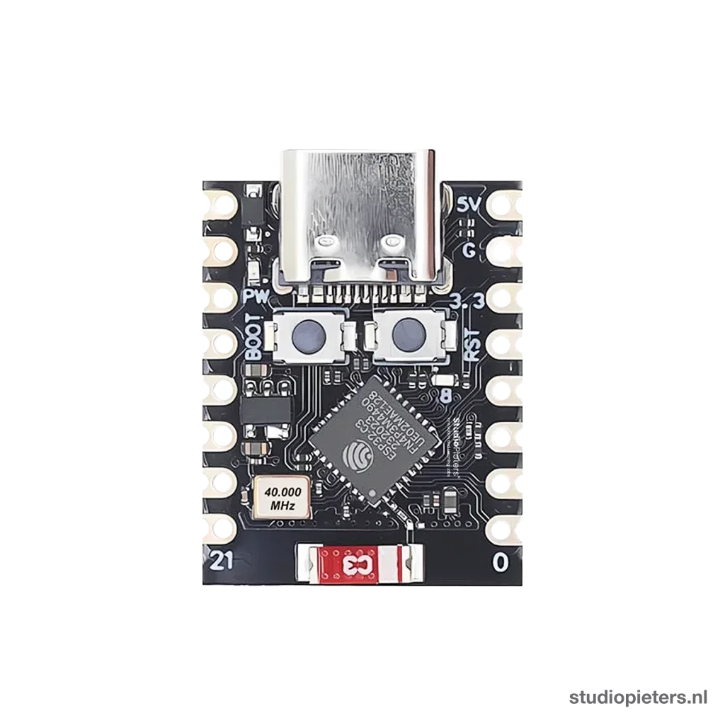
On the board you see the chip in the middle, a crystal, a voltage regulator, the USB-C connector, the BOOT and RST buttons, a PW power LED, a user LED and a ceramic antenna at the bottom edge, marked C3 on the drawing. The boards are made by many sellers, so details such as the exact LED pin can differ per clone.
Getting started
The board works over USB-C. If your computer shows no port, try a different cable first.
Hello World: blink an LED
On most boards the user LED sits on GPIO 8 and lights up when the pin is low. Check this on your own board, because clones differ.
Arduino IDE
const int LED_PIN = 8;

void setup() {
  pinMode(LED_PIN, OUTPUT);
}

void loop() {
  digitalWrite(LED_PIN, LOW);   // LED on
  delay(500);
  digitalWrite(LED_PIN, HIGH);  // LED off
  delay(500);
}
GPIO 8 is a strapping pin. Do not hold it low with other hardware while the board resets.
Specifications
Specifications of the ESP32-C3FH4 chip (Espressif ESP32-C3 datasheet) and of the Super Mini board.
Compute
| Chip | ESP32-C3FH4, 32-bit RISC-V single core, up to 160 MHz |
| Flash | 4 MB, inside the chip |
| SRAM | 400 KB (16 KB of it is cache), plus 8 KB RTC SRAM |
Radio
| Wi-Fi | 802.11 b/g/n, 2.4 GHz |
| Bluetooth | Bluetooth 5 LE |
Physical
| Logic level | 3.3 V, not 5 V tolerant |
| USB | USB-C, native USB serial/JTAG |
| Chip temperature range | -40 to 105 °C (the chip itself, not the board) |
| Header | 2 x 8 pins at 2.54 mm |
| Size | about 22.5 x 18 mm |
Dimensions
The board is about 22.5 mm long and 18 mm wide, with the 16 header pins at 2.54 mm pitch. The size comes from seller listings, because the Super Mini has no official drawing, so measure your own board before you design a case.

The picture is schematic: it shows the USB-C connector, the two buttons, the chip and the antenna as grey blocks, not their exact size.
Pinout diagram: back
With the USB-C connector at the top, the left row is 5V, G, 3.3, 4, 3, 2, 1, 0 and the right row is 5, 6, 7, 8, 9, 10, 20, 21. The numbers are GPIO numbers. The back of the board is marked ESP32-C3.

Pinout diagram: component side
The component side is mirrored: the same pins sit in the other row. Here the chip, the BOOT and RST buttons and the PW LED are visible. Pin 21 is at the bottom left and pin 0 at the bottom right.

GPIO map at a glance
The ESP32-C3 has 22 pins that can be used as GPIO, but the Super Mini brings out 13 of them.

GPIO quick reference
The pins on the header. GPIO 0 to 4 are on ADC1 and are the best choice for analog inputs.
| GPIO | Function | Note | Use |
|---|---|---|---|
| 0 | ADC1_CH0 | Free | Free |
| 1 | ADC1_CH1 | Free | Free |
| 2 | ADC1_CH2 | Strapping pin, floating by default, read at reset | Strapping |
| 3 | ADC1_CH3 | Free | Free |
| 4 | ADC1_CH4, JTAG MTMS | Free if you do not use JTAG | Free |
| 5 | ADC2_CH0, JTAG MTDI | The only ADC2 pin on the header | Free |
| 6 | JTAG MTCK | Free if you do not use JTAG | Free |
| 7 | JTAG MTDO | Free if you do not use JTAG | Free |
| 8 | Strapping pin, LED on most boards | Floating by default | Strapping |
| 9 | Strapping pin, BOOT button | Weak pull-up, low at reset selects download mode | Boot pin |
| 10 | GPIO only | Free | Free |
| 20 | UART0 RX | Serial input | Serial |
| 21 | UART0 TX | Serial output | Serial |
Not on the header: GPIO 11 to 17 connect to the flash inside the chip, and GPIO 18 and 19 are the USB D- and D+ lines. Do not use them.
Default pins in the Arduino core
- I2C: SDA on GPIO 8, SCL on GPIO 9
- SPI: SCK on GPIO 4, MISO on GPIO 5, MOSI on GPIO 6, SS on GPIO 7
- UART: TX on GPIO 21, RX on GPIO 20
These defaults come from the Arduino-ESP32 variant for this board and can differ per version, check pins_arduino.h. GPIO 8 and 9 are strapping pins, so it is safer to put I2C on other pins. On the ESP32-C3 you can route almost any pin to I2C, SPI and UART through the GPIO matrix.
Flashing and boot
Flashing normally just works over USB. If it does not:
| Pin or button | Purpose |
|---|---|
| BOOT (GPIO 9) | Hold during reset to enter download mode |
| RST (EN) | Restarts the chip |
| GPIO 20 and 21 | UART0, handy for logging or flashing with a USB-to-serial adapter |
Programming
The Arduino IDE (board “ESP32C3 Dev Module”), PlatformIO and ESP-IDF all work. Set USB CDC On Boot to Enabled in the Arduino IDE, so Serial prints over the USB-C connector.
Tips
- Use GPIO 0 to 4 for analog. They are on ADC1 and the best choice for sensors.
- Keep I2C off GPIO 8 and 9 if your sensors pull those pins low at start. Route I2C to other pins with
Wire.begin(SDA, SCL). - Use a good USB cable. A charge-only cable shows no serial port.
- Keep the antenna free. No metal or copper next to the ceramic antenna at the bottom edge.
Real gotchas
- No serial output. USB CDC On Boot is off by default in the Arduino IDE.
- Boot problems. The chip reads GPIO 2, 8 and 9 at every reset. Do not tie them to anything that pulls them to an unexpected level at that moment. Afterwards they work as normal pins.
- SPI and JTAG overlap. The default SPI pins are the JTAG pins, so avoid JTAG if you use SPI.
- 3.3 V only. A 5 V signal on any pin can damage the chip.
- The 5V pin is the USB supply. It is an output when powered over USB and an input when powered externally. Do not power the board from both at once.
- The Super Mini has no official datasheet. Board-level details such as the LED pin differ per clone.
Compared with other boards
For more pins, a card slot or a camera, look at a larger board.
| ESP32-C3 Super Mini | AI-C3 | XIAO ESP32-C3 | |
|---|---|---|---|
| Chip | ESP32-C3FH4 | ESP32-C3 | ESP32-C3 |
| USB | USB-C, native | see its guide | USB-C, native |
See also the AI-C3 pinout and the XIAO ESP32-C3 pinout.
What to build with it
- A small Wi-Fi sensor node with a temperature or humidity sensor.
- A Bluetooth LE beacon or remote.
- A tiny relay or LED controller that fits in a switch box.
Safety notes
Before you wire anything up
- All pins are 3.3 V. Never connect a 5 V signal directly.
- Pin drivers default to 20 mA per pin (10 mA on GPIO 2 and 3). That is the setting of the pin driver, not a safe load. Drive motors, relays and servos through a driver or a separate supply.
- Do not power the board from the 5V pin and USB at the same time.
Conclusion
The ESP32-C3 Super Mini is a small, cheap board with native USB, Wi-Fi 4 and Bluetooth 5 LE. Use GPIO 0 to 4 for analog, keep the strapping pins GPIO 2, 8 and 9 in mind, and turn USB CDC On Boot on to see serial output.
Related
 Reference
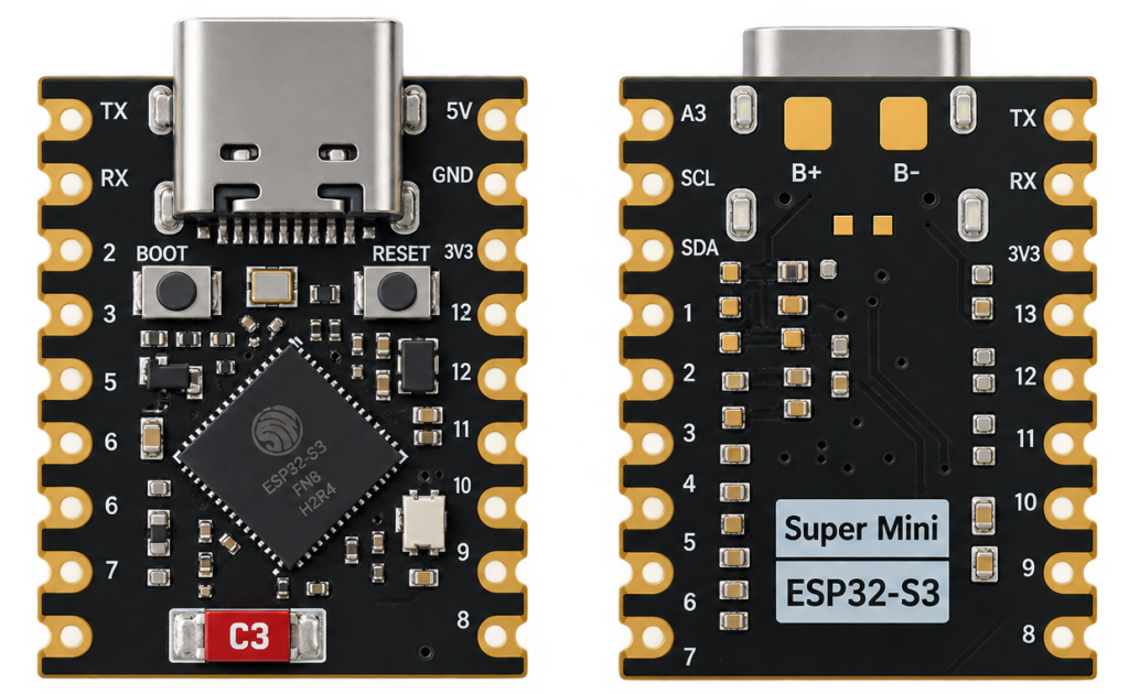
ESP32-S3 Zero / Super Mini Pinout
The Waveshare ESP32-S3-Zero pin reference: the chip, the pins and strapping pins, the quad versus octal PSRAM setting, power, code and the traps.
Read more
 Reference
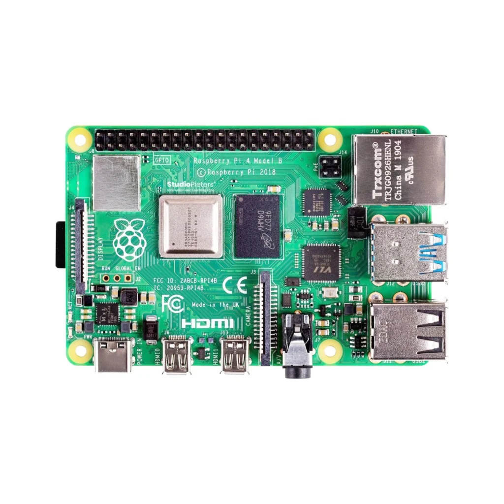
Raspberry Pi 4 Pinout
The Raspberry Pi 4 Model B is an 85 x 56 mm Linux computer with a quad-core 64-bit processor, up to 8 GB of memory, dual-band Wi-Fi and Gigabit Ethernet. This guide has the pinout of the 40-pin header on both sides of the board, every alternate function of the 28 GPIOs from the datasheet, the connectors, the electrical limits and the official dimensions.
Read more
 Reference
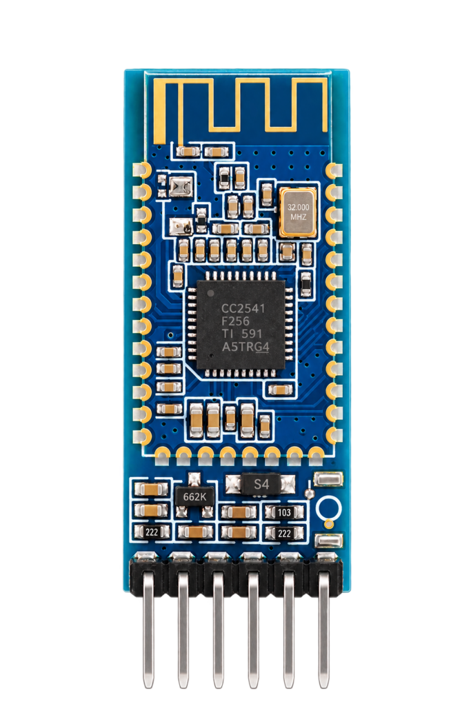
AT-09 Bluetooth LE Module Pinout
The AT-09 (MLT-BT05) is a Bluetooth 4.0 LE serial module for Arduino and other microcontrollers. The pinout of the 6-pin breakout board and of the 34-pad module on both sides, the datasheet values, the LED and role settings, and the AT commands.
Read more
More guides
Keep building.
From ESP32 HomeKit accessories to Arduino and ATtiny reference guides, there’s more where this came from.
All guides