I always wanted to connect something over Bluetooth if found this module the AT 09 BLE module. But first I need to know how it works.

AT 09 BLE Module
The AT-09 is a module that contains a BLE chip (a CC2540/CC2541). This module allows to perform serial communication with the BLE chip thanks to an Rx and a Tx pin. This module is also very similar to the HM-10 module and is also compatible with it.
Connecting the AT 09 BLE Module
Let’s start by connecting the Arduino with the AT 09 BLE module in order to turn it on. To achieve that, we only need these two pins
AT-09 GND <-> Arduino GND Pin
AT-09 VCC <-> Arduino 5V Pin or 3.3V Pin
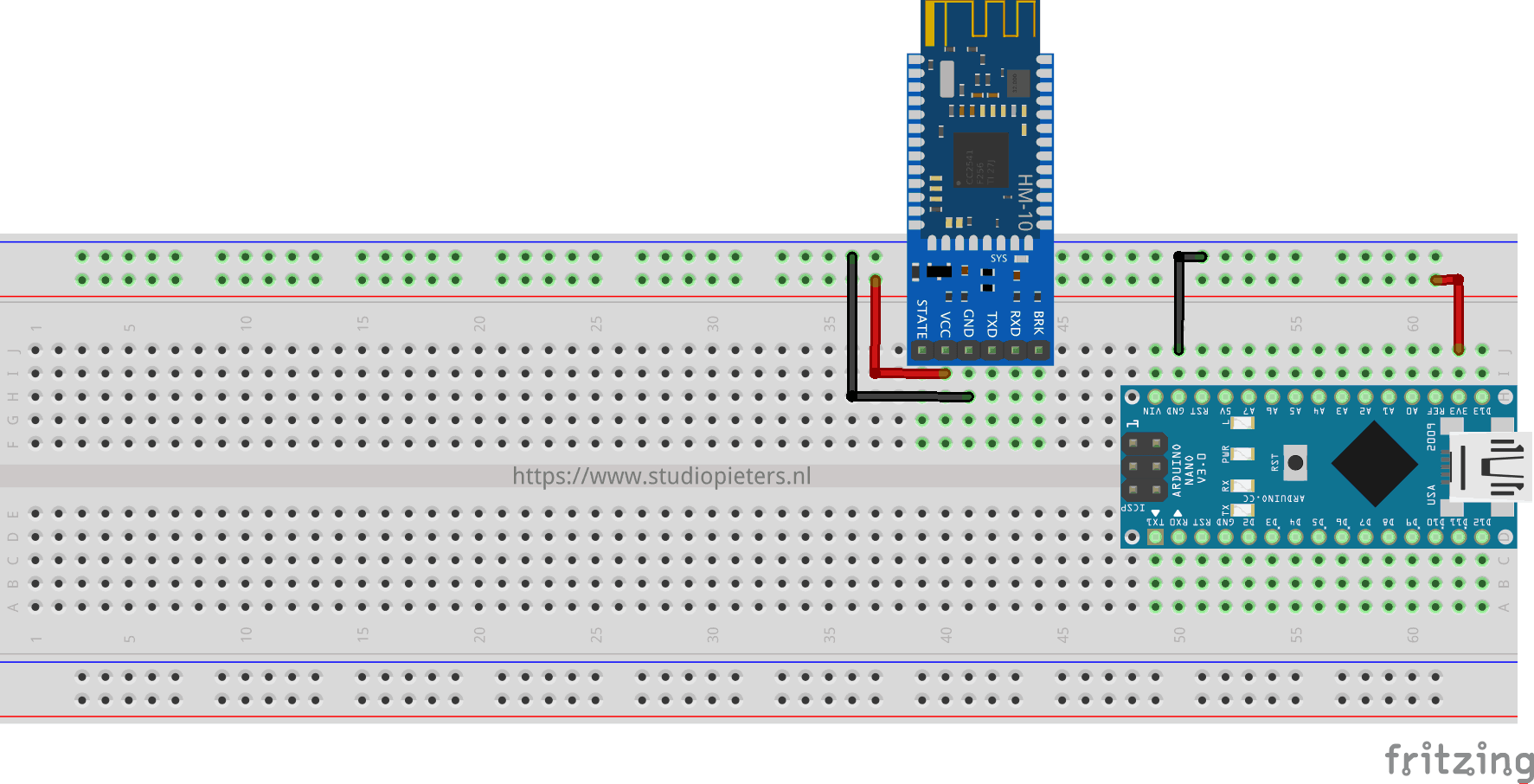
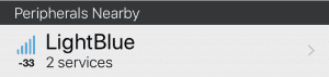
Turn on you Arduino, you should see the AT 09 BLE module led blink. If you have a BLE smartphone, you can also open a BLE scanning app to scan for the AT 09 BLE module. In my case, I used LightBlue | Explorer on my iPhone. The module was detected as device named ?. You can have a different result.
You can download the app here in the Apple App Store
![]()
If you do not happen to detect the module in this step, it may be simply a problem with the configuration of the module. So keep reading to learn how to configure it.
Sending our first command from the Arduino to the module
To allow the Arduino to communicate with the AT-09 BLE module, we use the serial interface (the TXD and RXD pins). Arduino allows to turn any pair of digital pins into a serial interface using the SoftwareSerial library included in the Arduino IDE. After establishing the serial connection, We can start transmitting data to the AT-09 BLE module. The module understands certain data as commands. These commands are the HM-10 AT commands. In order to send command to the module we need to:
- Connect the TXD and RXD pins of the module to any pair of Arduino pins other than 1 and 2.
- Ask the Arduino to convert that pair of pins into a serial interface.
- Send AT commands to the module and receive their responses.
Connect the TXD and RXD pins with the Arduino Nano like this.
AT-09 RXD <-> Arduino PIN 3
AT-09 TXD <-> Arduino PIN 2
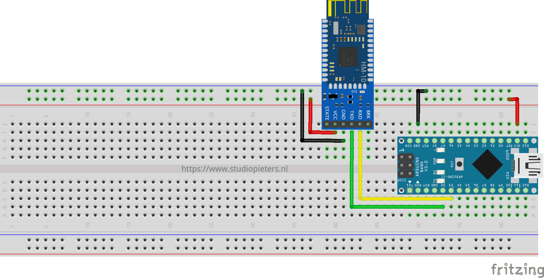
Connecting the AT 09 BLE module with the Arduino
Of course, you can connect the RXD and TXD pins to any Arduino Nano digital Pin (As long it is not pin 0 and 1).
Next, we declare the serial interface.
SoftwareSerial mySerial(2, 3); // RX, TX
This means that the arduino will use Pin2 will be used for Reception (RX) and Pin 3 for Transmission (TX).
After that, we can begin the serial communication by calling.
mySerial.begin(9600);
Serial.begin(9600);
and send the first command
sendCommand("AT");
The AT command allows to verify that we are correctly connected and return “OK” in that case. It acts like a ping command.
/* Project name: Arduino - AT 09 BLE module
   Project URI: https://www.studiopieters.nl/arduino-at-09-ble-module/
   Description: allow the Arduino to communicate with the AT-09 BLE module
   Version: 1.0.7
   License: MIT
*/

#include <SoftwareSerial.h>

SoftwareSerial mySerial(2, 3); // RX, TX

void setup() {
  // put your setup code here, to run once:
  mySerial.begin(9600);
  Serial.begin(9600);

  sendCommand("AT");
}

void sendCommand(const char * command){
  Serial.print("Command send :");
  Serial.println(command);
  mySerial.println(command);
  //wait some time
  delay(100);

  char reply[100];
  int i = 0;
  while (mySerial.available()) {
    reply[i] = mySerial.read();
    i += 1;
  }
  //end the string
  reply[i] = '\0';
  Serial.print(reply);
  Serial.println("Reply successful");
}

void loop() {

}
After running this loop, you should see an “OK” appear on the serial monitor.
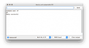
Congratulations, we sent our first command to the AT-09 module through the Arduino. Next we will configure the module as a BLE peripheral using commands.
Configuring the AT-09 as a BLE peripheral
configuring the AT-09 BLE module is done by so called AT commands. The goal of this section is to call the commands that allows you to do the following.
- Set the module as peripheral
- Set the service UUID
- Set the characteristic UUID
- Set a nice name to the peripheral
An important detail to note here is that the AT-09 BLE module allows only one service that contains only one characteristic when it is configured as a peripheral.
The HM-10 datasheet contains a section that lists AT commands. After some research, we find the commands that we are going to use.
- Set the module as peripheral if not set yet: AT+ROLE0 where 0 is for peripheral and 1 is for central.
- Set the service UUID: AT+UUIDuuid where uuid is the UUID of the service. It ranges from 0x0001~0xFFFE and defaults to 0xFFE0
- Set the characteristic UUID: AT+CHARuuid where uuid is the UUID of the characteristic. It ranges from 0x0001~0xFFFE and defaults to 0xFFE1
- Set a nice name to the peripheral: AT+NAMEnew_name where new_name is the new name that we want to set
Suppose we want this configuration
- Role: peripheral
- Name: LightBlue
- Service UUID: 0xFFE0
- Characteristic UUID: 0xFFE1
By consolidating all this information, we conclude to these commands.
- AT+ROLE0
- AT+NAMELightBlue
- AT+UUID0xFFE0
- AT+CHAR0xFFE1
On the Arduino sketch, we will send these commands during the setup() step since we will do it once when the board it boots up. It will take the command as a parameter, sends it, and displays its result. Note that I force a delay between sending a command and reading its reply. I did it because I noted in my tests that there is a lag between these two steps. So, better keep the delay. Here is the code.
/* Project name: Arduino - AT 09 BLE module
   Project URI: https://www.studiopieters.nl/arduino-at-09-ble-module/
   Description: allow the Arduino to communicate with the AT-09 BLE module
   Version: 1.0.7.B
   License: MIT
*/

#include <SoftwareSerial.h>

SoftwareSerial mySerial(2, 3); // RX, TX

void setup() {
  // put your setup code here, to run once:
  mySerial.begin(9600);
  Serial.begin(9600);

  sendCommand("AT");
  sendCommand("AT+ROLE0");
  sendCommand("AT+UUID0xFF00");
  sendCommand("AT+CHAR0xFF01");
  sendCommand("AT+NAMELightBlue");
}

void sendCommand(const char * command){
  Serial.print("Command send :");
  Serial.println(command);
  mySerial.println(command);
  //wait some time
  delay(100);

  char reply[100];
  int i = 0;
  while (mySerial.available()) {
    reply[i] = mySerial.read();
    i += 1;
  }
  //end the string
  reply[i] = '\0';
  Serial.print(reply);
  Serial.println("Reply successful");
}

void loop() {

}
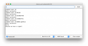
When you run the sketch, you should see the following output on the serial monitor.
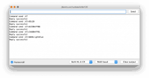
On the iOS side, the name of peripheral gets updated. I used LightBlue on iOS to perform the verification.
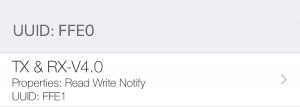
We can also verify the UUIDs of the services and characteristics.
We are making good progress. The next step consists in reading and writing data on the characteristic using the Arduino. The next section first focuses on reading the data available in that characteristic.
Reading the data on the AT-09’s characteristic
After configuring the AT-09 BLE module as a peripheral, our Arduino can easily read the data sent to its characteristic by reading TXD pin. Any connected central can inject data into the characteristic. Please note that the only available characteristic can store up to 20 bytes of random data.
In this code we see there is a function that puts the characteristic data into a buffer and then writes it to the serial monitor. The loop() function does simply a call to the readSerial() function.
/* Project name: Arduino - AT 09 BLE module
   Project URI: https://www.studiopieters.nl/arduino-at-09-ble-module/
   Description: allow the Arduino to communicate with the AT-09 BLE module
   Version: 1.0.7.C
   License: MIT
*/

#include <SoftwareSerial.h>

SoftwareSerial mySerial(2, 3); // RX, TX
int PIN_EN_OUT = 4;
int PIN_STATE_IN = 5;


void setup() {
  // put your setup code here, to run once:
  mySerial.begin(9600);
  Serial.begin(9600);

  sendCommand("AT");
  sendCommand("AT+ROLE0");
  sendCommand("AT+UUID0xFFE0");
  sendCommand("AT+CHAR0xFFE1");
  sendCommand("AT+NAMELightBlue");
}

void sendCommand(const char * command){
  Serial.print("Command send :");
  Serial.println(command);
  mySerial.println(command);
  //wait some time
  delay(100);

  char reply[100];
  int i = 0;
  while (mySerial.available()) {
    reply[i] = mySerial.read();
    i += 1;
  }
  //end the string
  reply[i] = '\0';
  Serial.print(reply);
  Serial.println("Reply successful");
}

void readSerial(){
  char reply[50];
  int i = 0;
  while (mySerial.available()) {
    reply[i] = mySerial.read();
    i += 1;
  }
  //end the string
  reply[i] = '\0';
  if(strlen(reply) > 0){
    Serial.println(reply);
    Serial.println("Houston we have a signal!");
  }
}

void loop() {
  readSerial();
  delay(500);
}
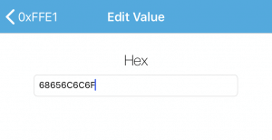
Now open the LightBlue app and click on write new value.

Then type 68 65 6c 6c 6f (Hello in Hex).
When you run the sketch, you should see the following output on the serial monitor.
Next, we will see how to write data to the characteristic on the Arduino side and how to receive on the central side.

Writing data on the AT-09 characteristic
You can now guess how to write data to the module. The answer is of course, by using mySerial.write(). The loop() method will print a value that gets incremented after each write.
/* Project name: Arduino - AT 09 BLE module
   Project URI: https://www.studiopieters.nl/arduino-at-09-ble-module/
   Description: allow the Arduino to communicate with the AT-09 BLE module
   Version: 1.0.7.D
   License: MIT
*/

#include <SoftwareSerial.h>

SoftwareSerial mySerial(2, 3); // RX, TX
int PIN_EN_OUT = 4;
int PIN_STATE_IN = 5;


void setup() {
  // put your setup code here, to run once:
  mySerial.begin(9600);
  Serial.begin(9600);

  sendCommand("AT");
  sendCommand("AT+ROLE0");
  sendCommand("AT+UUID0xFFE0");
  sendCommand("AT+CHAR0xFFE1");
  sendCommand("AT+NAMELightBlue");
}

void sendCommand(const char * command) {
  Serial.print("Command send :");
  Serial.println(command);
  mySerial.println(command);
  //wait some time
  delay(100);

  char reply[100];
  int i = 0;
  while (mySerial.available()) {
    reply[i] = mySerial.read();
    i += 1;
  }
  //end the string
  reply[i] = '\0';
  Serial.print(reply);
  Serial.println("Reply successful");
  delay(50);
}

void writeSerialToBLE(int value) {
  mySerial.println(value);
}

void writeToBLE(char value) {
  Serial.print("Writing hex :");
  Serial.println(value, HEX);
  mySerial.write(value);
}

char j = 0;
void loop() {
  writeToBLE(j);
  j += 1;
  delay(500);
}
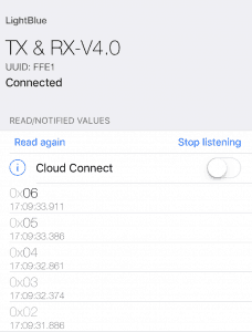
This sketch will write these values one by one: 1, 2, 3, 4, 5, etc. After each write, the AT-09 BLE module will update the characteristic and also send a notification. On our central app, we will receive notifications following this order: 1, 2, 3, 4, 5, etc.
Now open the LightBlue app and click on LightBlue.
Then open the TX&RX Properties.
and select Listen for notifications. Now you will see the messages that arrives from your AT-09 BLE module.
Application
Time to build a realise example a small cool temperature / Humidity application. sending temperature and humidity to the iPhone through BLE. Here we will need a temperature / humidity sensor. I am using the DHT22 sensor here.
We will connect the sensor to the Arduino following this scheme.
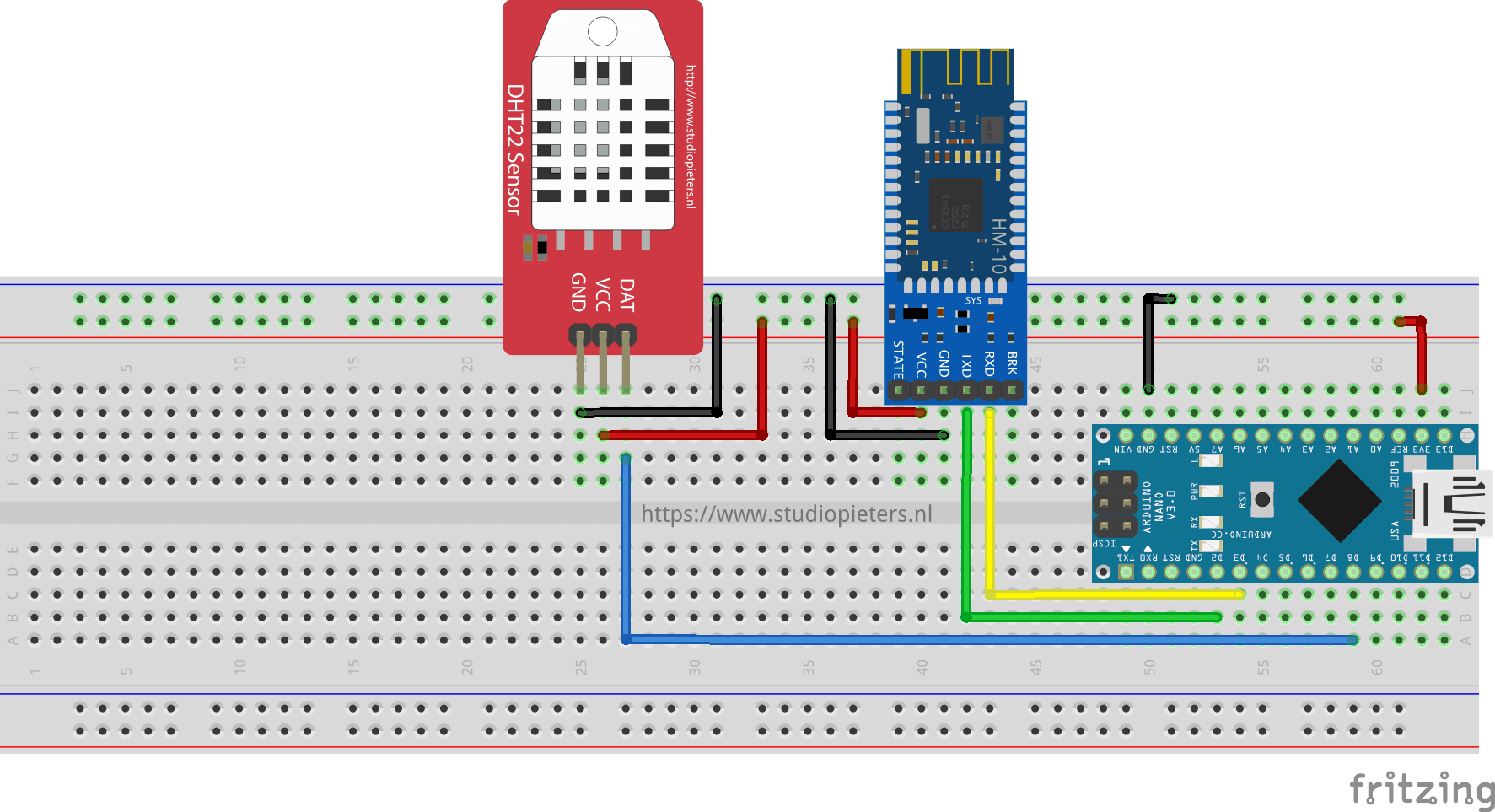
After establishing the connections, we will need to read the temperature from one of the free pin’s. The Used library that allows to read the temperature in Celsius or Fahrenheit. we just need to send the string to the serial port of the AT-09 BLE module.
/* Project name: Arduino - AT 09 BLE module
    Project URI: https://www.studiopieters.nl/arduino-at-09-ble-module/
    Description: allow the Arduino to communicate with the AT-09 BLE module
    Version: 1.0.7.E
    License: MIT
*/

#include <SoftwareSerial.h>
#include "DHT.h"

SoftwareSerial mySerial(2, 3); // RX, TX

int PIN_EN_OUT = 4;
int PIN_STATE_IN = 5;

#define DHTPIN 8     // what digital pin we're connected to
#define DHTTYPE DHT22   // DHT 22  (AM2302), AM2321
DHT dht(DHTPIN, DHTTYPE);

void setup() {
  // put your setup code here, to run once:
  mySerial.begin(9600);
  Serial.begin(9600);

  dht.begin();

  sendCommand("AT");
  sendCommand("AT+ROLE0");
  sendCommand("AT+UUID0xFFE0");
   sendCommand("AT+CHAR0xFFE1");
  sendCommand("AT+NAMELightBlue");
}

void sendCommand(const char * command) {
  Serial.print("Command send :");
  Serial.println(command);
  mySerial.println(command);
  //wait some time
  delay(100);

  char reply[100];
  int i = 0;
  while (mySerial.available()) {
    reply[i] = mySerial.read();
    i += 1;
  }
  //end the string
  reply[i] = '\0';
  Serial.print(reply);
  Serial.println("Reply successful");
  delay(50);
}

void writeSerialToBLE(int value) {
  mySerial.println(value);
}

void loop() {
  // Wait a few seconds between measurements.
  delay(2000);

  // Reading temperature or humidity takes about 250 milliseconds!
  // Sensor readings may also be up to 2 seconds 'old' (its a very slow sensor)
  float h = dht.readHumidity();
  // Read temperature as Celsius (the default)
  float t = dht.readTemperature();
  // Read temperature as Fahrenheit (isFahrenheit = true)
  float f = dht.readTemperature(true);

  // Check if any reads failed and exit early (to try again).
  if (isnan(h) || isnan(t) || isnan(f)) {
    Serial.println("Failed to read from DHT sensor!");
    return;
  }

  // Compute heat index in Fahrenheit (the default)
  float hif = dht.computeHeatIndex(f, h);
  // Compute heat index in Celsius (isFahreheit = false)
  float hic = dht.computeHeatIndex(t, h, false);

  //Serial.print("Humidity: ");
  //Serial.print(h);
  //Serial.print(" %\t");
  //Serial.print("Temperature: ");
  Serial.print(t);
  Serial.println(" °C");
  mySerial.print(t);
  mySerial.println(" °C");
  //Serial.print(f);
  //Serial.print(" *F\t");
  //Serial.print("Heat index: ");
  //Serial.print(hic);
  //Serial.print(" *C ");
  //Serial.print(hif);
  //Serial.println(" *F");
}
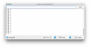
When you run the sketch, you should see the following output on the serial monitor.
Now open the LightBlue app and click on LightBlue.
Then open the TX&RX Properties.
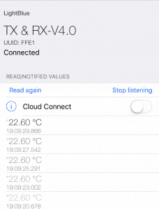
and select Listen for notifications. Now you will see the messages that arrives from your AT-09 BLE module.
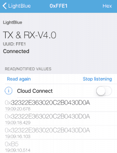
As you can see it displays the temperature in Hex, now press hex in the upper right corner and select UTF-8 now you will see the temperature in plain text.
Oke now that we have a “real life” working application we can go further with our bluetooth and make some awesome things.

Happy coding!
DOWNLOAD ALL FILES FOR THIS PROJECT ON GITHUB.

DO YOU HAVE ANY QUESTIONS? LEAVE A COMMENT DOWN HERE.
REFERENCE
Yassine Benabbas (JAN 29 2017), Using the AT-09 BLE module with the Arduino, https://tinyurl.com/ychdoak3, Adafruit (Out 26 2016), Arduino library for DHT11DHT22, etc Temp & Humidity Sensors , https://github.com/adafruit/DHT-sensor-library Lightblue | Explorer (Nov 1 2016), The industry-leading BLE test app for iOS and Android. , https://punchthrough.com
SaveSave
SaveSave