UPDI? Never heard of it? You may be familiar with the ATtiny series of microprocessors from Microchip, such as the ATtiny85 or ATtiny2313. These chips powered small systems like the Digispark series. Unfortunately, they had limited Flash (usually no more than 8K) and even more limited RAM (usually less than 1K). Now a new series of ATtiny chips are available with more memory and functionality. They even compete with the more expensive and larger ATmega range of chips.
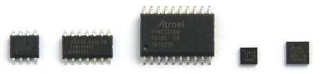
One of the biggest changes in these processors is the way they are programmed. They use a system called Unified Program and Debug Interface (UPDI for short). In this build you can create a UPDI programmer for under a few euros rather than having to fork out many hundreds of euro’s for a commercial one.

The Schematic
Hardware
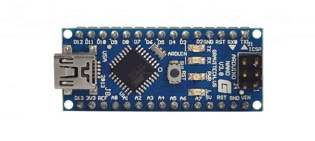
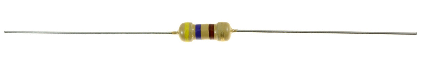
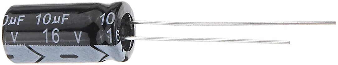
A Nano, resistor and capacitor are all the basic components required.
Arduino Nano
Resistor 4,7K
Capacitor 10UF 16V

Program the Arduino Nano
Unzip the attached “SpenceKonde – jtag2updi.zip” file into your Arduino program folder and program the Arduino Nano.
Note: It’s OK that the jtag2updi.ino file is empty, as the actual code resides in the other files.
Building the UPDI Programmer
The 4K7 resistor goes between pin D6 on the Arduino Nano and the top centre pin on the header. Use some insulation material to ensure the lead doesn’t short with other components. Adding the resistor, capacitor and heat-shrink cover. The 10uF capacitor is put between the GND and RST pins. Make sure the positive end (usually marked with a line or + symbol) of the capacitor is soldered to the RST pin.
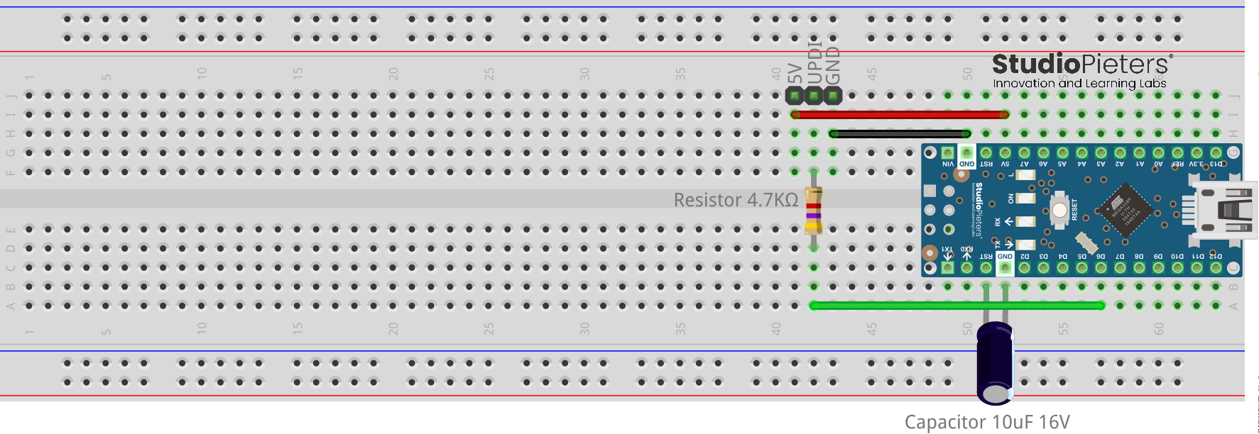
Just make sure the wire colours used make it obvious which wire is +5V, which wire is GND and which wire is UPDI. My Cables in the example, Red – 5V, Green – UPDI and Black – GND.

Using the programmer
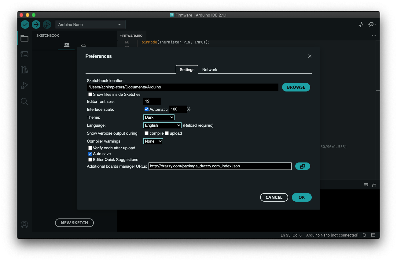
To use the programmer, you must first install the megaTinyCore into the Arduino IDE via the board manager.
- File → Preferences, enter the following URL in “Additional Boards Manager URLs“
http://drazzy.com/package_drazzy.com_index.json
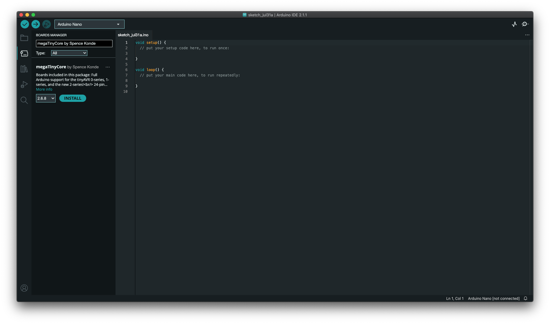
- Tools → Boards → Boards Manager…
- Select “megaTinyCore by Spence Konde” and click “Install“.
Once the board has been installed in the IDE, select it from the Tools menu.
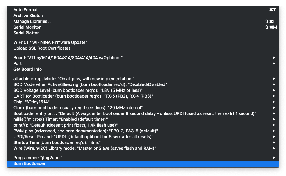
Select Board:, chip:, clock:, Port: To your desired settings. The Programmer needs to be set to jtag2updi (megaTinyCore).

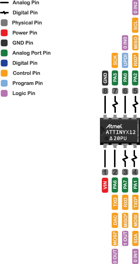
ATTINY xx12 Pin OUT
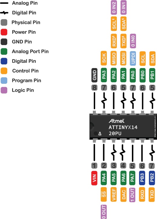
ATTINY xx14 Pin OUT
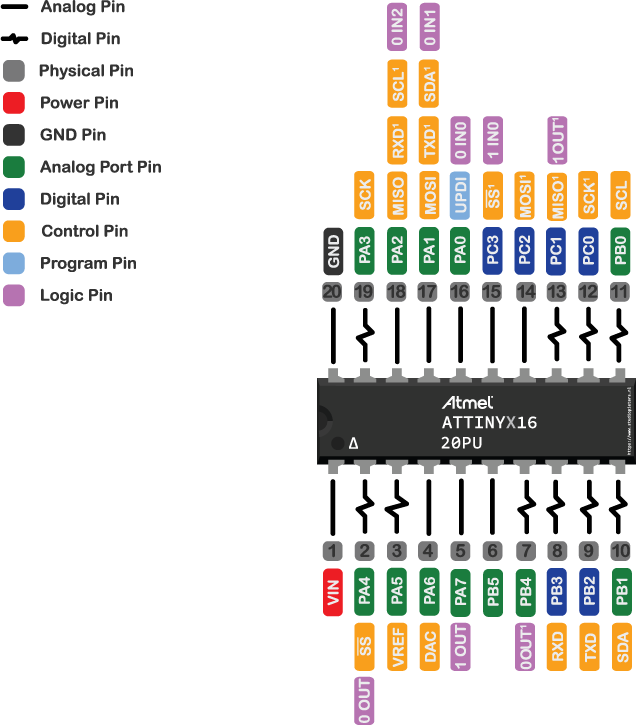
ATTINY xx16 Pin OUT
ATTINY xx17 Pin OUT
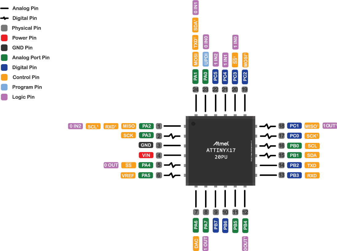
To access the physical IO pins in the Arduino IDE using digitalRead, digitalWrite, analogRead or analogWrite, use the pin map above to determine the pin number to use.
Note: Unlike the ATmega328, the new ATtiny processors don’t have separate analogue pins. Whether a pin is analogue or digital depends on which function you use to access it.
References
[1] Microchip, “Microcontrollers and Microprocessors / 8-bit MCUs / AVR® MCUs” https://www.microchip.com/en-us/products/microcontrollers-and-microprocessors/8-bit-mcus/avr-mcus
[2] Arduino, “Arduino is an open-source electronics platform based on easy-to-use hardware and software” https://www.arduino.cc
[3] hackster “Create Your Own UPDI Programmer” https://www.hackster.io/john-bradnam/create-your-own-updi-programmer-1e55f1