Maybe you want to make a PCB with SMD components. To do this, you need a so-called reflow oven. Various projects can be found on the internet to make such an oven. But here comes the problem, most projects use a custom PCB based on SMD components. This is the same if you contact the IT department that your mail is no longer working, and you are told that they will mail you the solution…….?

So here’s the solution, the ReflowMate®. This will be a low-cost reflow hot plate for SMD components and will be homemade! I’ve used a small heating plate that costs around 7 dollars. And the rest is also very low-cost. A few dollars for the Arduino, the screen and the relay, a few more dollars for small components such as buttons, the switch, a fan, and wires. So, let’s get started. BE CAREFUL WORKING WITH HIGH VOLTAGE.


Hardware
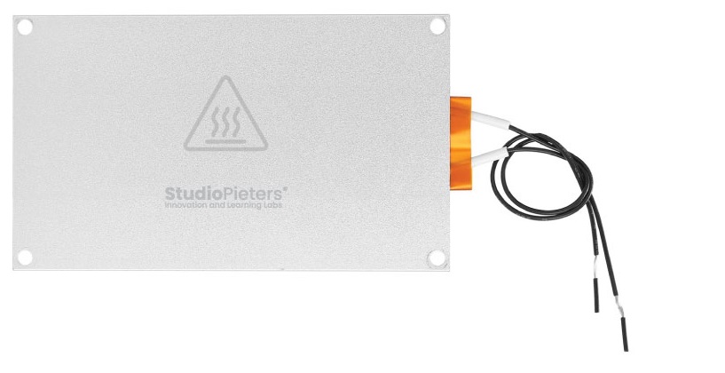
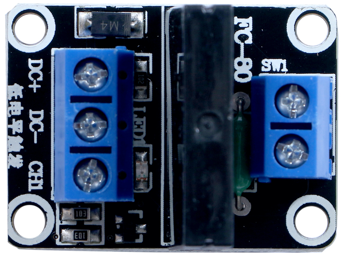
I want to keep this project low cost, so it would be cheaper than buying a reflow station. The plate I use has an internal heating resistor of around 450 ohms, so at 360V it could deliver around 280W of power. On AliExpress, the plate was marked as 400W, but I’m not sure that it could reach that. Anyway, I’ve realized that we don’t need more than 3 hundred watts. It is made of aluminium, which will transfer the heat very fast. To control the power, we require a solid-state relay.
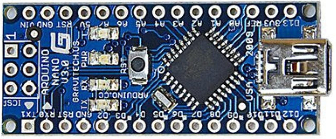
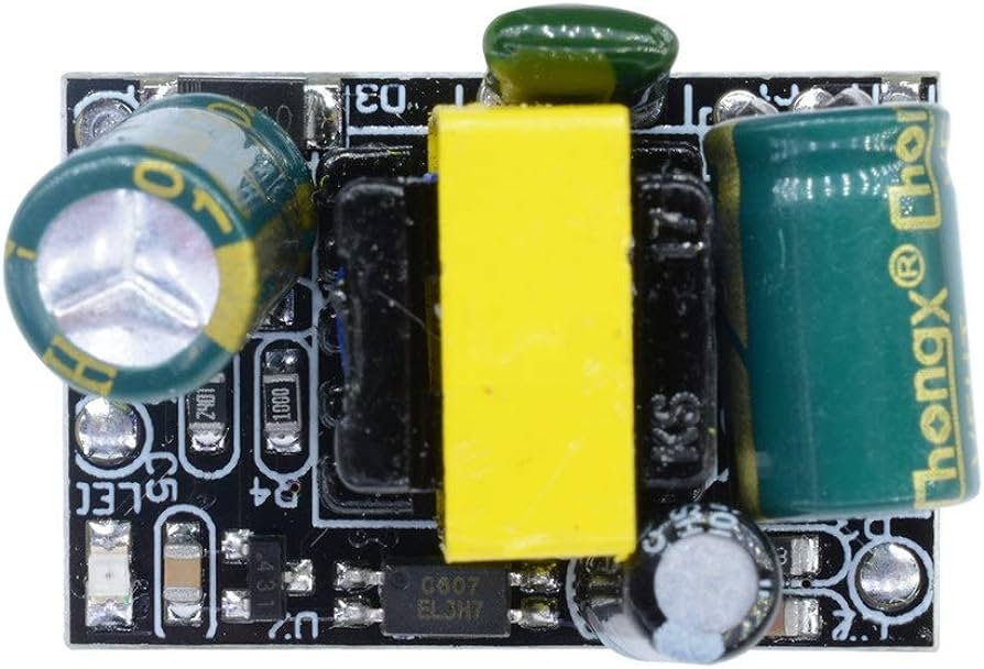
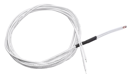
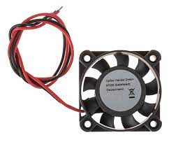
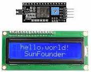
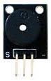
The goal is to control it with an Arduino. So, obviously, we also require an Arduino which in this case, I will use again the Arduino NANO. To show the values, I will use a 16 by 2 LCD screen with the i2c communication module, so it is easier to control. To measure the temperature, I will now use a thermistor instead of a thermocouple. We also need to use a 5V fan. The heater works at 220V, but the rest of the digital part is working at 5V, so, to lower the voltage, I will use a small converter. To turn the entire circuit on and off, you can use a switch, I will use a plain power cable. I also want to add a buzzer like this one for alarm notifications.
- 1 x Hot Plate 220VAC 400W
- 1 x SSR
- 1 x Arduino NANO
- 1 × 220V to 5V 700Ma converter
- 1 × 3950 thermistor 100K
- 1 × 5 V Fan
- 1 × 16×2 i2c LCD
- 1 x Buzzer
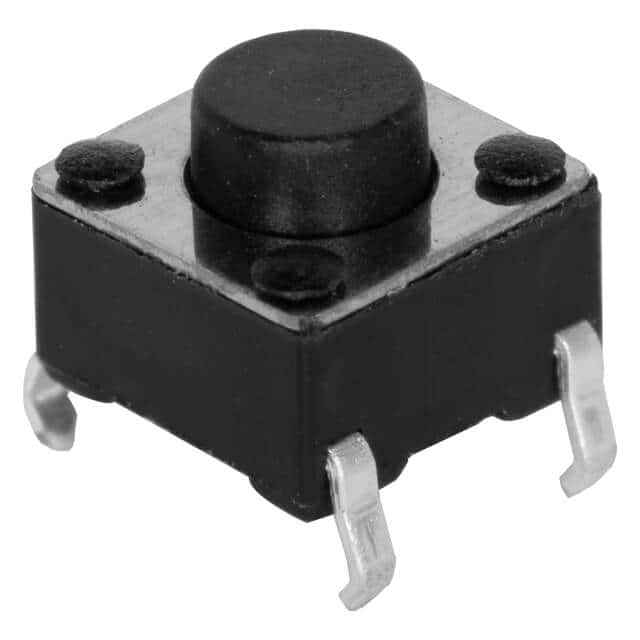
- 2 x Push buttons
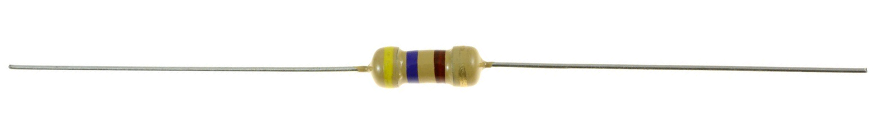
- 4.7 kΩ Resistor
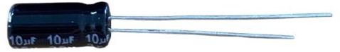
- 10µF 6,3V Capacitor
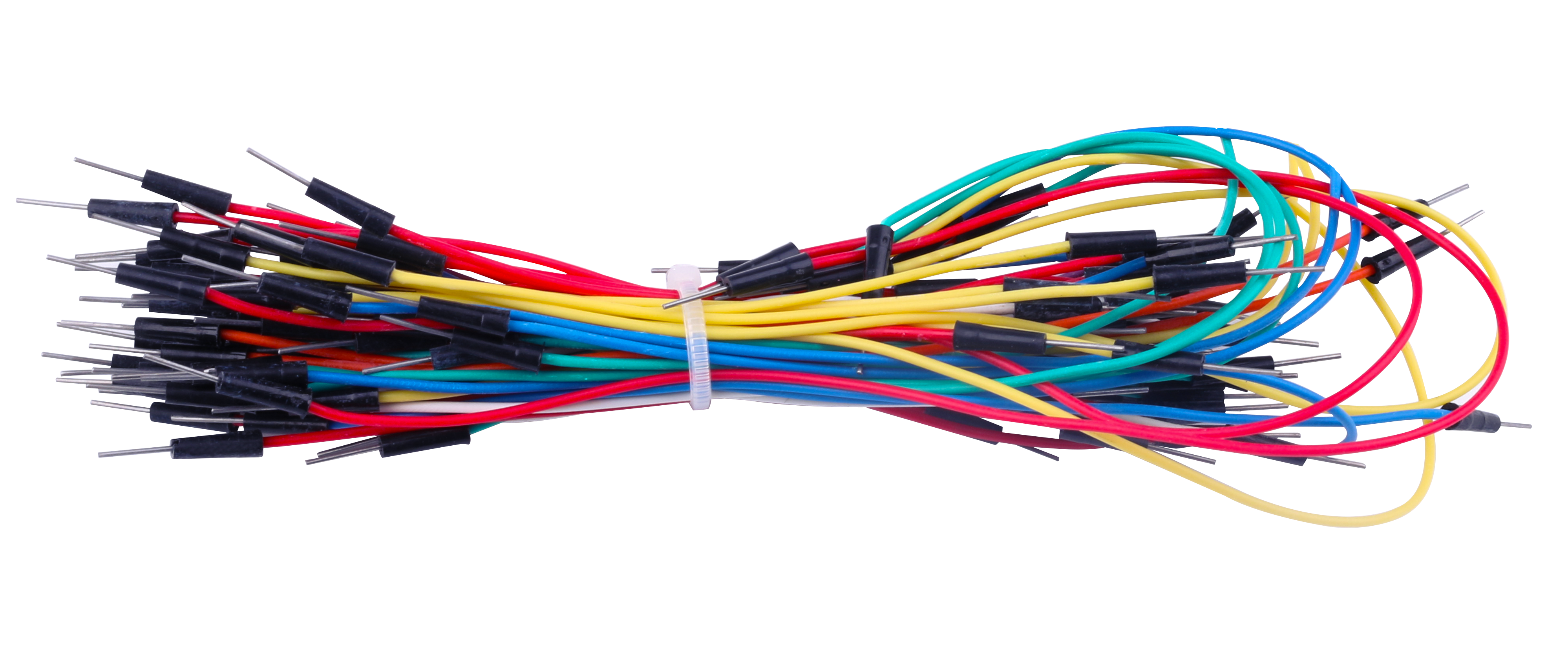
- Wires

What is Reflow Soldering?
Reflow soldering is a process in which a solder paste (a sticky mixture of powdered solder and flux) is used to temporarily attach one or thousands of tiny electrical components to their contact pads. And after which the entire assembly is subjected to controlled heat. The solder paste reflows in a molten state, creating permanent solder joints. Heating may be accomplished by passing the assembly through a reflow oven.
System Reflow Curve
The reflow curve of the temperature of a certain point on the SMA with time when the SMA passes through the reflow oven furnace. The temperature curve provides an intuitive method to analyse the temperature change of a component during the entire reflow soldering process. Below is the proper reflow curve a heater should achieve for perfect soldering of components.
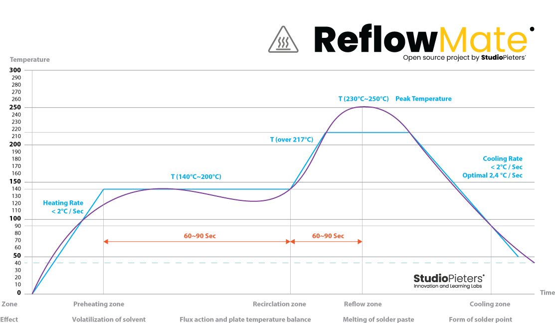
The ReflowMate manages to achieve this temperature curve by adjusting the switching duty of MOSFET which results in variation in heat. The temperature sensor continuously reads the temperatures and sends back to the Microcontroller. Therefore, a solution with “standard” components to make a ReflowMate that works just as well!

Circuit
In order to understand what is happening in the circuit, it is required to understand the actual function of the circuit along with the knowledge on the components used and its behaviour in the circuit in different current & voltage condition. A circuit diagram (electrical diagram, elementary diagram, electronic schematic) is a graphical representation of an electrical circuit.
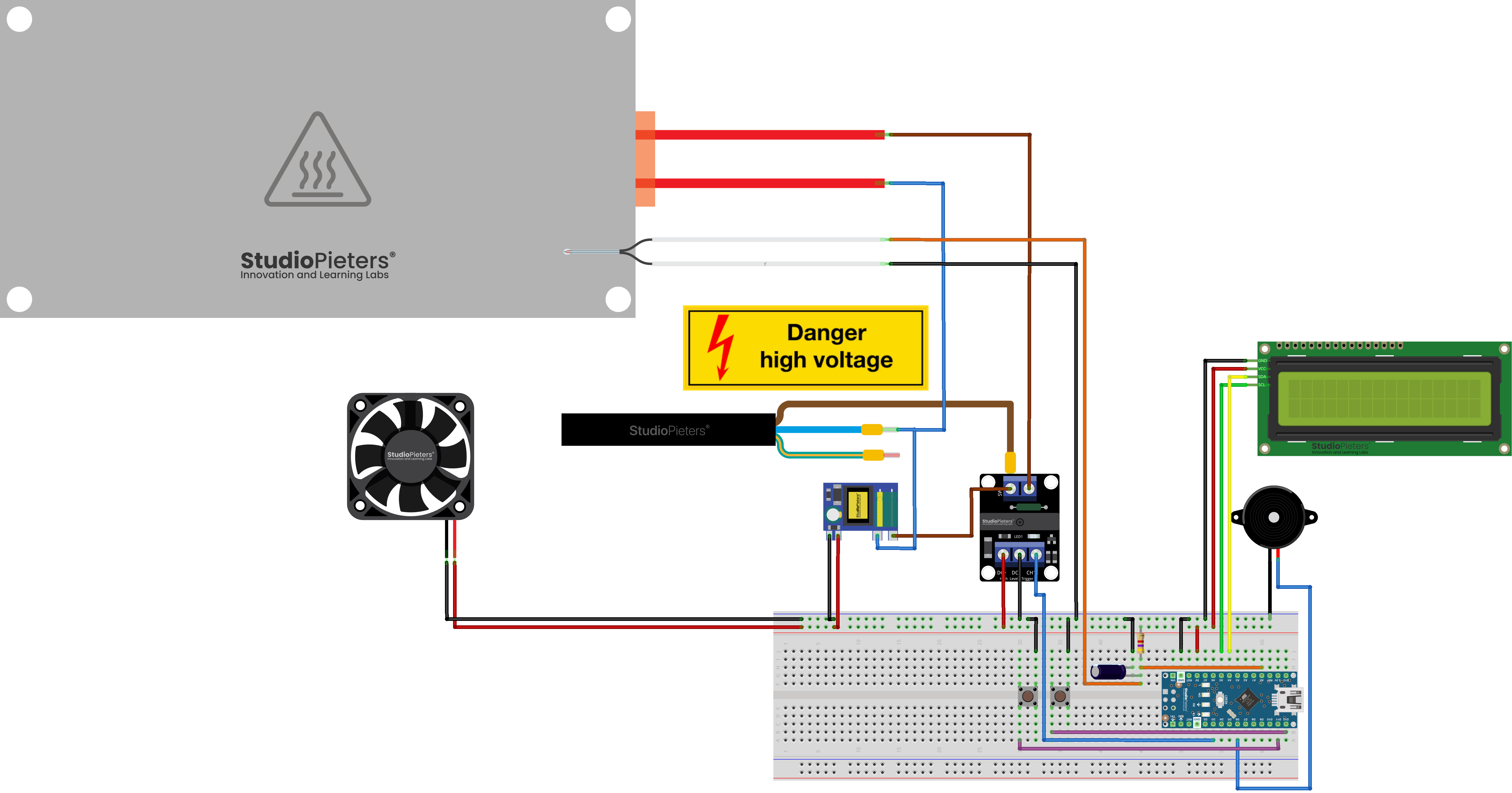
The schematic for this project above is how you make your setup. Be careful working with 220VAC because it is quite dangerous, so don’t connect it to the main outlet till you are sure everything is okay!
Electricity is dangerous and can cause personal injury or DEATH, as well as other property loss or damage if not used or constructed properly. If you have any doubts whatsoever about performing do-it-yourself electrical work, PLEASE do the smart thing and hire a QUALIFIED SPECIALIST to perform the work for you.

Add the pull-up 4.7 kΩ Resistor for the thermistor and a 10µF 6,3V Capacitor. Attach the thermistor with good connection to the hot plate, so it will measure the temperature. Supply all the digital part with 5V from the converter, but check the output first with a multimeter and make sure it’s 5V, otherwise it might burn the Arduino and the rest.
Code
Now that you have built your test Circuit, we can upload our code. We use Arduino IDE to upload the code to our Arduino Nano Module.
Click the download button below to download the complete code and needed Libraries.
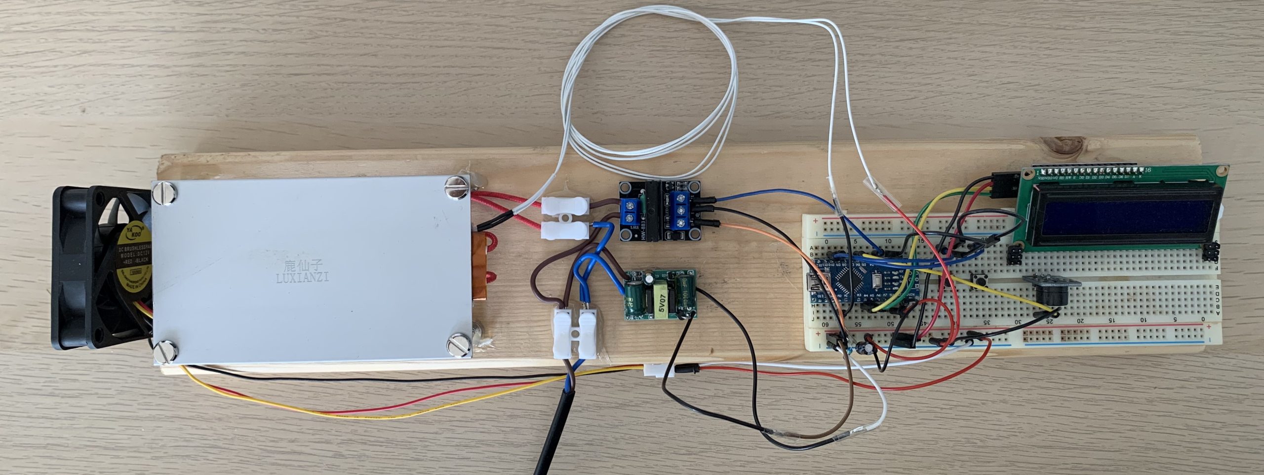
Connect it to power, the LCD will start and tell the user to select a mode. On the screen we can see temperature, if the relay is ON and when the mode is running, we can see the set point, the PWM value and the elapsed time in seconds. I prepare a testing PCB with some solder paste and I add a few components using the tweezers. I place the PCB over the heating plate. From the menu I select mode 1, which is the only mode for now, and I press run. We start with the ramp where we go up to 150 degrees, then the soak part, and finally we go above that temperature and reflow the components. Once the components are soldered, we enter the cooldown mode. At this point, you can remove the PCB from the plate. Yay! The reflow process was a success!

Reference
Arduino, Arduino is an open-source electronics platform, https://www.arduino.cc electronoobs, REFLOW HOT PLATE – V2, http://electronoobs.com/eng_arduino_tut161.php