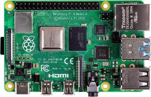
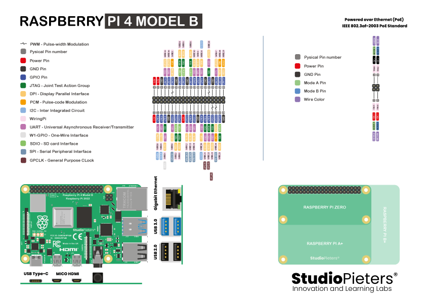
In this post, we’ll be taking a closer look at the Raspbrry Pi® hardware, and more specifically, the Raspbrry Pi® 4 Model B pinout. Raspbrry Pi® is based on the 64-bit quad-core Cortex A-72(ARM v8) processor@1.5GHz. The Raspbrry Pi® pinout consists of a high-performance 64-bit quad-core processor, dual-display support at resolutions up to 4K via a pair of micro-HDMI ports, hardware video decode at up to 4Kp60, 4GB of RAM, dual-band 2.4/5.0GHz wireless LAN, Bluetooth 5.0, Gigabit Ethernet, USB 3.0 and PoE capability (via a separate PoE HAT add-on). The dual-band wireless LAN and Bluetooth have modular compliance certification, allowing the board to be designed into end products with significantly reduced compliance testing, improving both cost and time to market.
Power
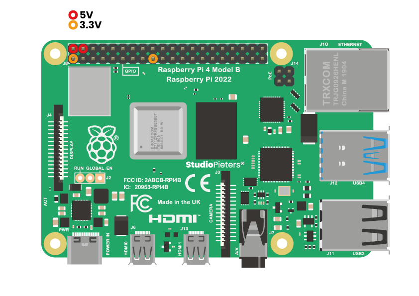
The 5V power pins are connected directly to the Pi’s power input and will capably provide the full supply current of your mains adaptor, minus that used by the Pi itself. With a decent power supply, such as the official Pi adaptor, you can expect to pull about 1.5A. This varies by Pi model and adapter used. Devices that require a high current- such as LED panels, long LED strips or motors- should use an external power supply. All Raspbrry Pi® models since the B+ can provide up to 500mA on the 3.3V pins, thanks to a switching regulator. In some cases it may be possible to draw more but, due to lack of documentation and testing on the actual limits, 500mA is given as a rule of thumb. The 3.3V supply pin on the early Raspbrry Pi® had a maximum available current of only 50mA. The 5V supply coupled with a 3.3V regulator is recommended for powering 3.3V projects.
Ground
The Ground pins on the Raspbrry Pi® are all electrically connected, so it doesn’t matter which one you use if you’re wiring up a voltage supply. Generally the one that’s most convenient or closest to the rest of your connections is tidier and easier, or alternatively the one closest to the supply pin that you use. For example, it’s a good idea to use Physical Pin 17 for 3.3V and Physical Pin 25 for ground when using the SPI connections, as these are right next to the important pins for SPI0.

I2C – Inter Integrated Circuit
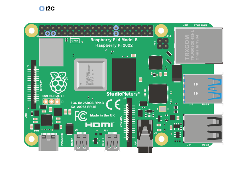
GPIO 2 and GPIO 3 – the Raspberry Pi’s I2C pins – allow for two-wire communication with a variety of external sensors and devices. The I2C pins include a fixed 1.8 kΩ pull-up resistor to 3.3V. They are not suitable for use as general purpose IO where a pull-up might interfere. I2C is a multi-drop bus, multiple devices can be connected to these same two pins. Each device has its own unique I2C address. You can verify the address of connected I2C peripherals with a simple line:
sudo apt-get install i2c-toolssudo i2cdetect -y 1
You can then access I2C from Python using the smbus library:
import smbusDEVICE_BUS = 1DEVICE_ADDR = 0x15bus = smbus.SMBus(DEVICE_BUS)bus.write_byte_data(DEVICE_ADDR, 0x00, 0x01)
GPIO 0 and GPIO 1 – I2C0 – can be used as an alternate I2C bus, but are typically used by the system to read the HAT EEPROM.
PWM – Pulse-width Modulation
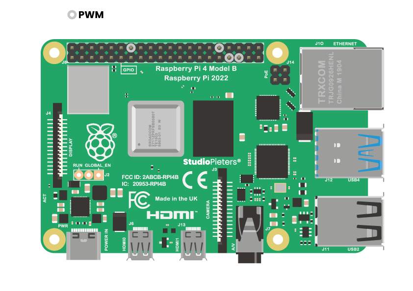
PWM (Pulse-width Modulation) is a method of creating an analog voltage by toggling a digital pin on and off.
SPI – Serial Peripheral Interface
SPI0 pins are GPIO 7, 8, 9, 10, 11 and SPI1 pins are GPIO 16, 17, 18, 19, 20, 21. Known as the four-wire serial bus, SPI lets you attach multiple compatible devices to a single set of pins by assigning them different chip-select pins. To talk to an SPI device, you assert its corresponding chip-select pin. By default the Pi allows you to use SPI0 with chip select pins on CE0 on GPIO 8 and CE1 on GPIO 7. You can enable SPI1 with a dtoverlay configured in “/boot/config.txt”, for example:
dtoverlay=spi1-3cs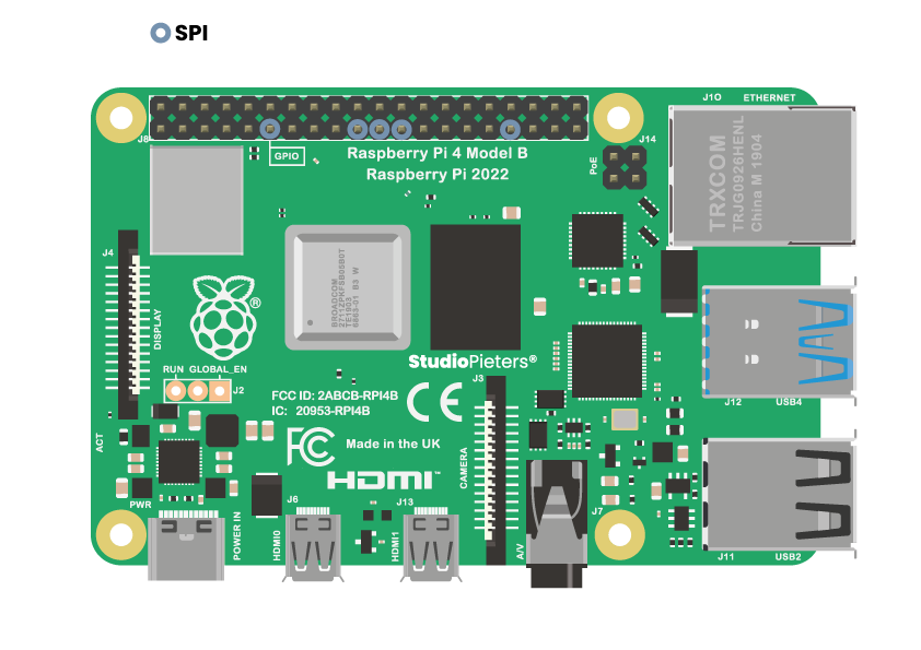
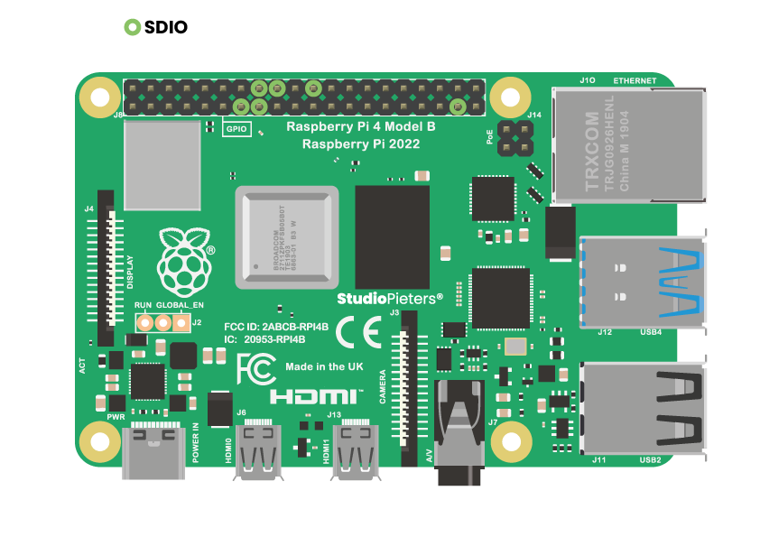
SDIO – SD Card Interface
SDIO is the SD host/eMMC interface on the Raspbrry Pi®. SD host signals are normally used for the microSD slot. These pins are “SD host” on Alt0 and “eMMC” on Alt3.
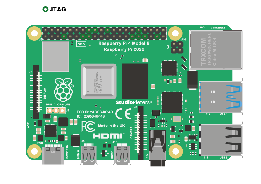
JTAG – Joint Test Action Group
JTAG is a standardised interface for debugging integrated circuits which you can use to debug your Raspbrry Pi® .There are two separate JTAG interfaces available on the Pi: Alt5 on GPIOs 4, 5, 6, 12 and 13 and Alt4 on GPIOs 22, 23, 24, 25, 26 and 27.
UART – Universal Asynchronous Receiver/Transmitter
UART pins in BCM mode are: 14, 15 and UART pins in WiringPi are: 15, 16. UART is an asynchronous serial communication protocol, meaning that it takes bytes of data and transmits the individual bits in a sequential fashion. Asynchronous transmission allows data to be transmitted without the sender having to send a clock signal to the receiver. Instead, the sender and receiver agree on timing parameters in advance and special bits called ‘start bits’ are added to each word and used to synchronize the sending and receiving units.
UART is commonly used on the Pi as a convenient way to control it over the GPIO, or access the kernel boot messages from the serial console (enabled by default). It can also be used as a way to interface an Arduino, bootloaded ATmega, ESP8266, etc with your Pi. Be careful with logic-levels between the devices though, for example the Pi is 3.3V and the Arduino is 5V. Connect the two and you might conjure up some magic blue smoke.
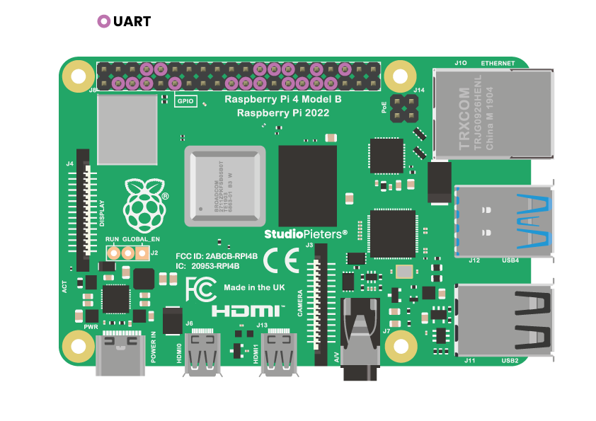
Raspbrry Pi® 2/3 have two UARTs, uart1 and uart0. Raspbrry Pi® 4 has four additional UARTs available. Only uart0/1 is enabled over GPIO pin 14/15 by default. The additional UARTs can be enabled through the device tree overlays.
Assuming you have WiringPi-Python installed, the following python example opens the Pi’s UART at 9600baud and puts ‘This is your Pi!’
import wiringpiwiringpi.wiringPiSetup()serial = wiringpi.serialOpen('/dev/ttyAMA0',9600)wiringpi.serialPuts(serial,'This is your Pi!')
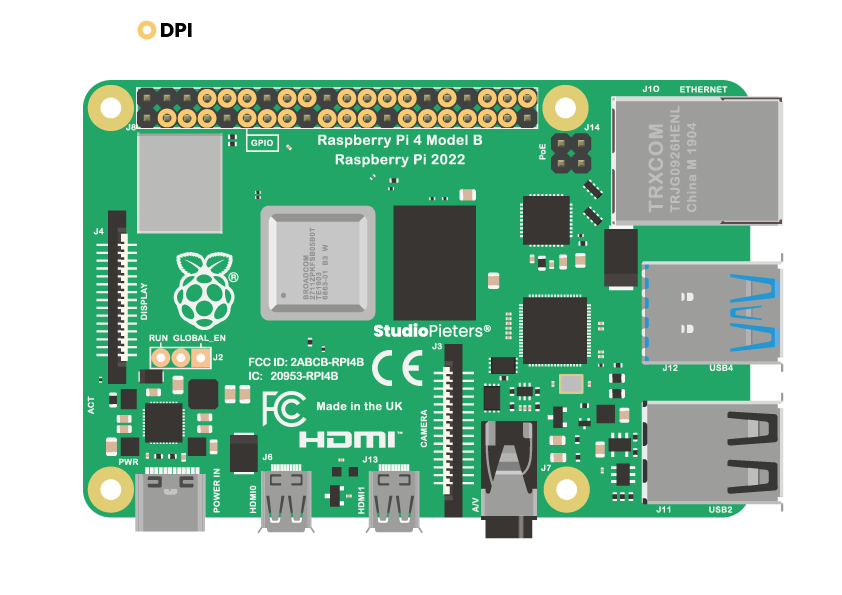
DPI – Display Parallel Interface
One of the alternate functions selectable on bank 0 of the Raspbrry Pi® GPIO is DPI. DPI (Display Parallel Interface) is a 24-bit parallel interface with 28 clock and synchronisation signals. This interface allows parallel RGB displays to be attached to the Raspbrry Pi® GPIO either in RGB24 (8 bits for red, green and blue) or RGB666 (6 bits per colour) or RGB565 (5 bits red, 6 green, and 5 blue). It is available as alternate function 2 (ALT2) on GPIO bank 0. The pinout presented here is for the RGB24 mode..
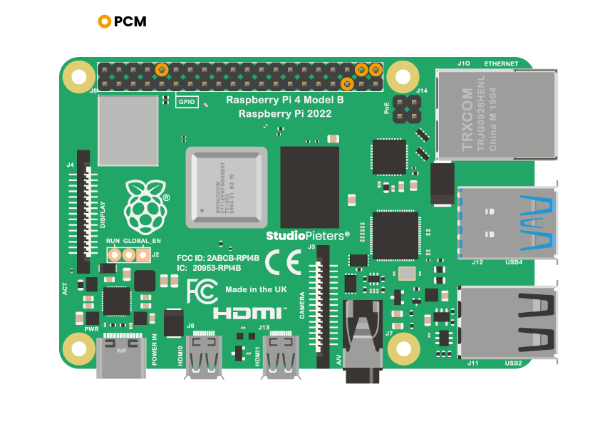
PCM – Pulse-code Modulation
PCM (Pulse-code Modulation) is a digital representation of sampled analog. On the Raspbrry Pi® it’s a form of digital audio output which can be understood by a DAC for high quality sound.
W1-GPIO – One-Wire Interface
One-wire is a single-wire communication bus typically used to connect sensors to the Pi. The Raspbrry Pi® supports one-wire on any GPIO pin, but the default is GPIO 4. To enable the one-wire interface you need to add the following line to /boot/config.txt, before rebooting your Pi:
dtoverlay=w1-gpioor
dtoverlay=w1-gpio,gpiopin=xif you would like to use a custom pin (the default is GPIO 4). Alternatively you can enable the one-wire interface on demand using raspi-config, or the following:
sudo modprobe w1-gpioNewer kernels (4.9.28 and later) allow you to use dynamic overlay loading instead, including creating multiple 1-Wire busses to be used at the same time:
sudo dtoverlay w1-gpio gpiopin=4 pullup=0 # header pin 7sudo dtoverlay w1-gpio gpiopin=17 pullup=0 # header pin 11sudo dtoverlay w1-gpio gpiopin=27 pullup=0 # header pin 13
once any of the steps above have been performed, and discovery is complete you can list the devices that your Raspbrry Pi® has discovered via all 1-Wire busses (by default GPIO 4), like so:
ls /sys/bus/w1/devices/Using w1-gpio on the Raspbrry Pi® typically needs a 4.7 kΩ pull-up resistor connected between the GPIO pin and a 3.3v supply (e.g. header pin 1 or 17). Other means of connecting 1-Wire devices to the Raspbrry Pi® are also possible, such as using i2c to 1-Wire bridge chips.

WiringPi
WiringPi is an attempt to bring Arduino-wiring-like simplicity to the Raspbrry Pi®. The goal is to have a single common platform and set of functions for accessing the Raspbrry Pi® GPIO across multiple languages. WiringPi is a C library at heart, but it’s available to both Ruby and Python users who can “gem install wiringpi” or “pip install wiringpi” respectively. WiringPi uses its own pin numbering scheme, this page illustrates how WiringPi numbers your GPIO pins.
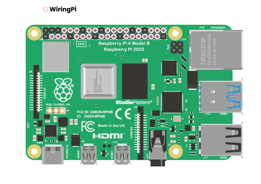
WiringPi has been deprecated by its original author. For more information about, and support with the ongoing community maintained version and ports, see the WiringPi GitHub org: https://github.com/WiringPi
GPCLK – General Purpose CLock
General Purpose Clock pins can be set up to output a fixed frequency without any ongoing software control.
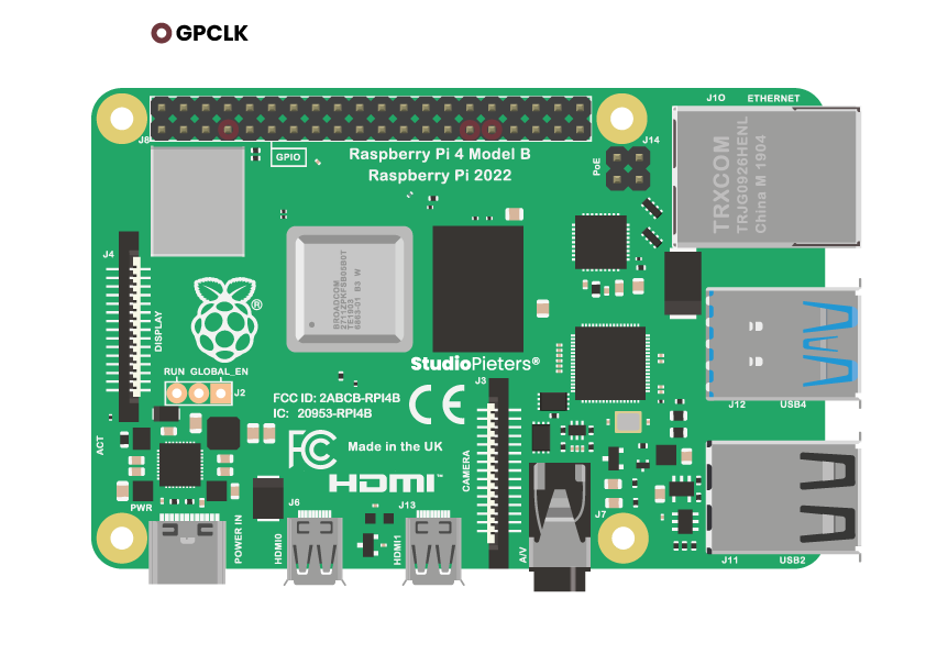
The following clock sources are available:
0 0 Hz Ground1 19.2 MHz oscillator2 0 Hz testdebug03 0 Hz testdebug14 0 Hz PLLA5 1000 MHz PLLC (changes with overclock settings)6 500 MHz PLLD7 216 MHz HDMI auxiliary8-15 0 Hz Ground
Other frequencies can be achieved by setting a clock-divider in the form of SOURCE/(DIV_I + DIV_F/4096). Note, that the BCM2835 ARM Peripherals document contains an error and states that the denominator of the divider is 1024 instead of 4096.
Graphical Pinout
The Raspberry header is the key to its ability to interface with the real world. The Pi either uses a 40-pin or 26-pin depending on the model and it is important to understand how those pins are arranged and labelled. The GPIO.BCM option means that you are referring to the pins by the “Broadcom SOC channel” number, these are the numbers after “GPIO” in the green circles around the outside of the below diagram.
Raspberry Pi GPIO Card
Whenever working with the GPIO ports of your Raspberry Pi you face challenge to remember which pin corresponds to what. E.g. which pins do I use when connecting a SPI device or where do I find the GPIO #17 pin?

To assist this I have put together a printable GPIO Card you easily can fit directly on your GPIO header. Although initially made for the 40 pin GPIO header of the A+, B+ and the version 2 model B boards, you could easily fit it on a version 1 model B rev 2 board as well (simply ignore the last 14 pins).
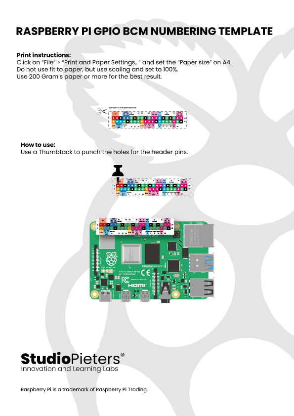
After printing use a needle, paperclip or any thin metal pin to punch out the center of each GPIO pin on the paper and then mount into through the GPIO header on your Pi board.
Pinout Sheet
Reference
Raspberry Pi, Raspberry Pi Documentation, https://www.raspberrypi.com/products/raspberry-pi-4-model-b Raspberry Pi Foundation, Raspberry Pi Documentation, https://www.raspberrypi.org Raspberry Pi Pinout, The Raspberry Pi GPIO pinout guide, https://pinout.xyz/pinout/i2c#