The upload procedure for ESP32 boards is a little different from a standard Arduino procedure. Most Arduino’s will automatically reset when a new program is being uploaded, and will automatically enter programming mode. On some ESP boards you have to manually enter programming mode, and on the bare-bones modules, you even have to reset them manually. However, there are some simple circuits you can use to get automatic uploads.

ESP32
The modules are based on a small board with an antenna at the top and SMD tabs along the sides and one end. The tabs are spaced in millimetres, so are not compatible with common header pins, breadboards and so on. So, if you are not surface mounting them to a customized PCB, the best option is to use the module with a breakout board, which will then equip it with standard headers. To do this, buy the module with breakout board kit, which you can also get ready soldered and tested for you to use. The breakout pins will plug into a breadboard, or you can connect with Dupont Leads.

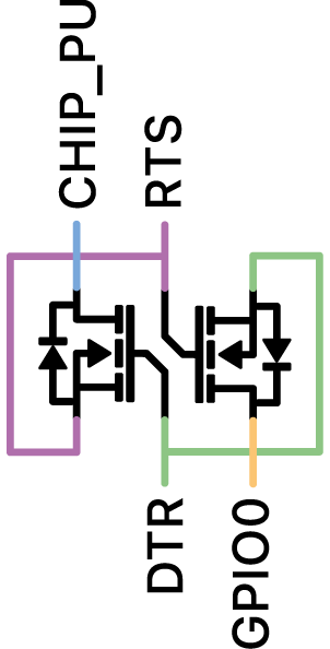
If the USB-to-Serial converter you’re using has a DTR flow control line like a FTDI Module, you can automate the reset signal. When sending data to the ESP, the DTR line goes low, and stays low for some time. To reset the ESP, we need a low pulse on the RST pin. This only applies to boards without an on-board USB-to-Serial converter.
Data transfer and upload
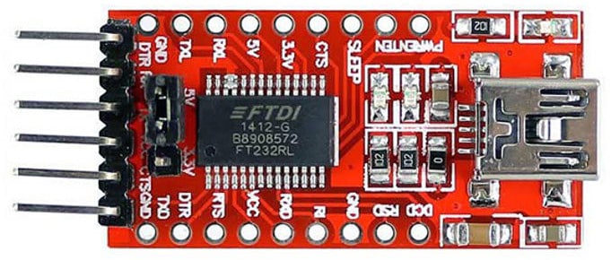
Uploading data to the ESP32 is done using serial data. This means that to connect it to a computer (MAC or PC) you will need to use a USB to Serial module such as an FTDI breakout board.
Note: FTDI is not the only kind of chip for serial to USB data transfer, there are others such as the CH340G and you may need to install drivers if they do not work automatically.
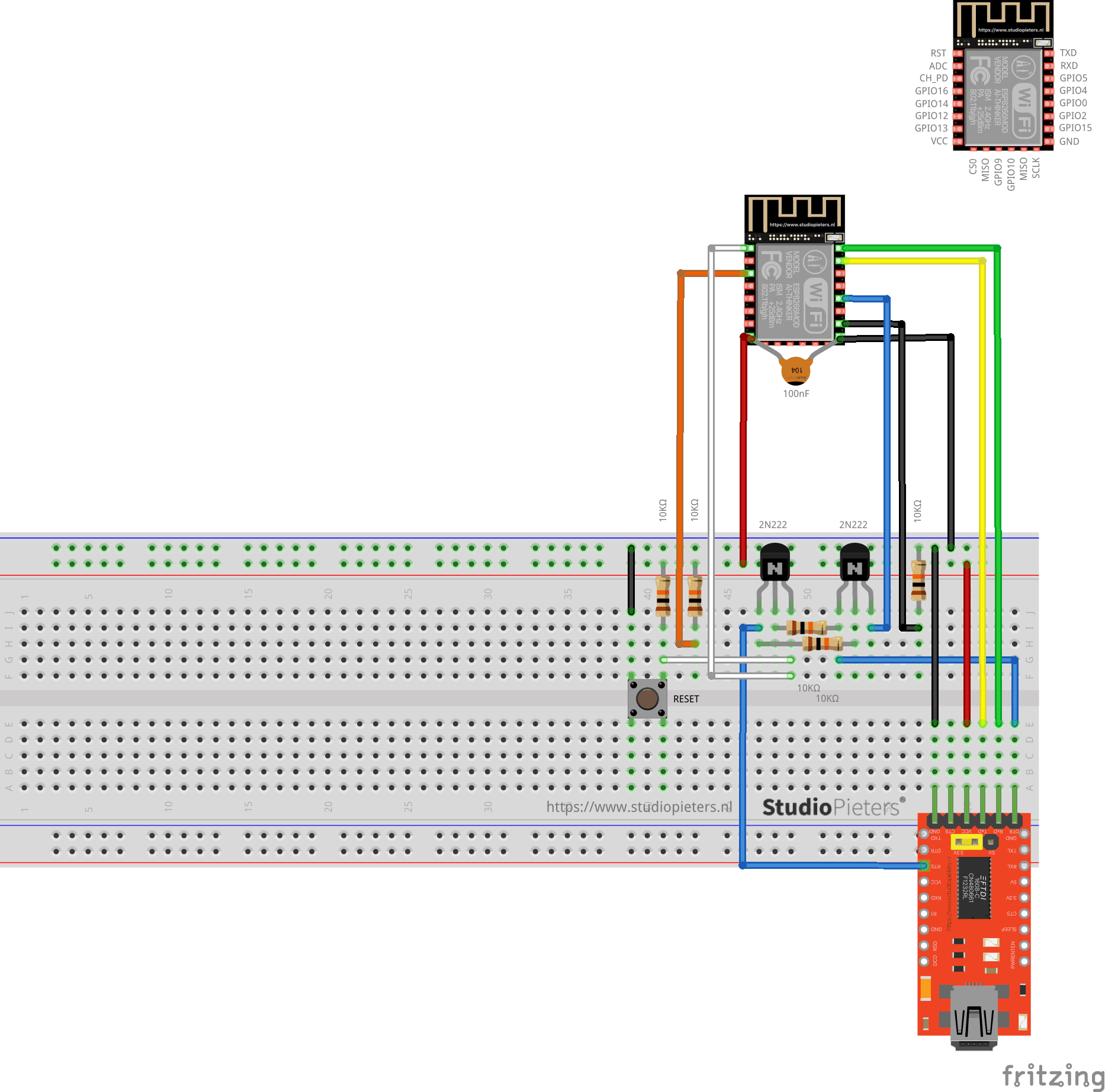
To program the ESP32, it will need to be put into UART programming mode. This involves pulling down GPIO pin 0 to ground via a resistor. During an upload the module will need to reset, change to programming mode and then change back to normal operating mode. This can either be done manually with a couple of push buttons, or can be automated using connections from the USB-Serial adaptor and a few extra components.
To upload the data, connect Rx to Tx and Tx to Rx between the two boards. Also, connect the GND of the programming module to the GND of the ESP32. For Auto reset programming, connect RTS and DTR from the programmer to the ESP32 as shown in the circuit below, if these are not available you will need to use the Manual Reset circuitry and method. Whichever method you choose, it is a good idea to have a reset button connected as well, so you can just start a program running again if you need to.

Automatic Program & Reset
There is also an automatic method for uploading and resetting. To use this, some additional circuitry will be needed, using a couple of small NPN MOSFETS.
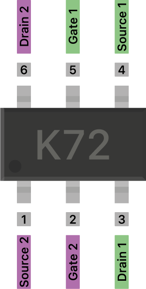
2N7002DW
A 6-pin dual N-Channel MOSFET chip. In some old modules, the MOSFET chip has a part number 702 while in many new modules it’s a different chip marked as K27. Actually, they’re 2N7002DW (702) and 2N7002KDW (K27) chips, and the latter features an integrated ESD protection mechanism.
What is N-Channel MOSFET?
The MOSFET formed in which the conduction is due to the channel of majority charge carriers called electrons. When this MOSFET is activated as ON, this condition results in the maximum amount of the current flow through the device. This type of MOSFET is defined as N-channel MOSFET.
How does it work
This 2N7002DW is being able to reset ESP32 or put it in boot mode.
| DTR (G2) | RTS (G1) | EN (D2) | GPIO0 (D1) |
| 1 | 1 | 1 | 1 |
| 0 | 0 | 1 | 1 |
| 1 | 0 | 0 | 1 |
| 0 | 1 | 1 | 0 |
Circuit
An electronic circuit is composed of individual electronic components, such as resistors, transistors, capacitors, inductors and diodes, connected by conductive wires or traces through which electric current can flow. It is a type of electrical circuit and to be referred to as electronic, rather than electrical, generally at least one active component must be present.
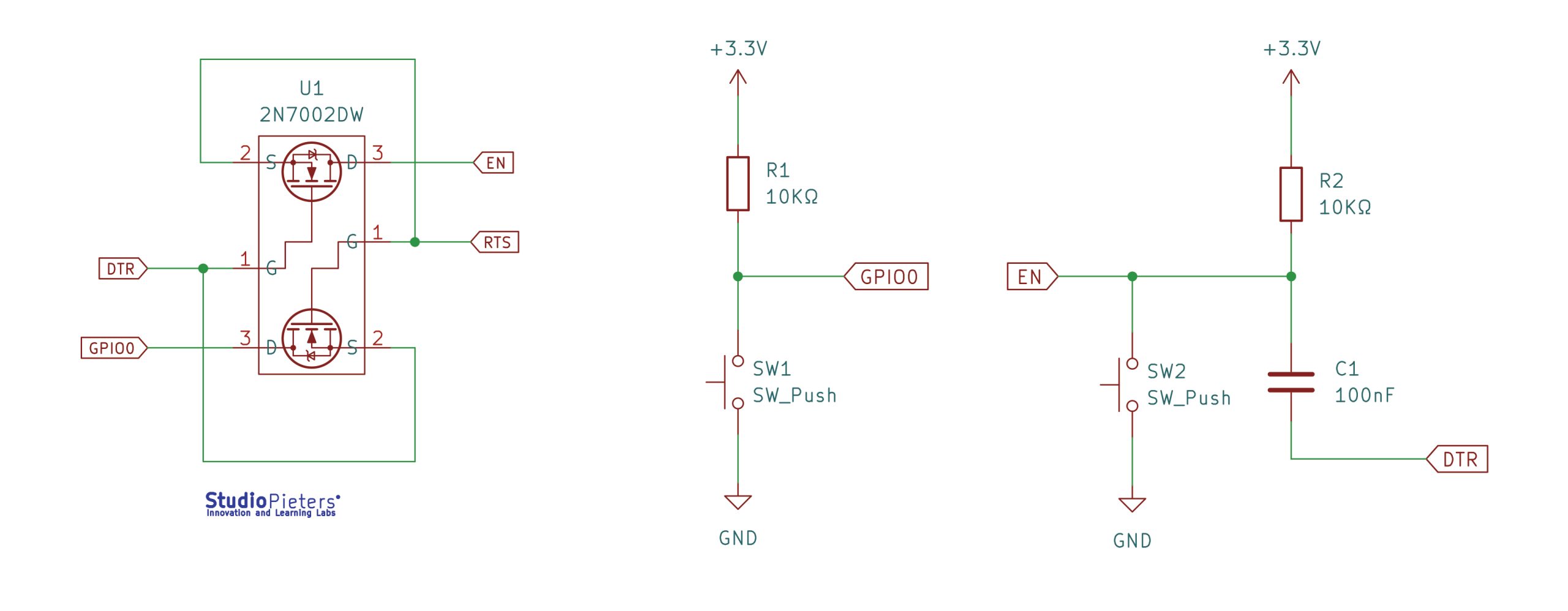

Scheme

Testing the setup
I build the scheme like here above. Then I used the esptool.py to flash your device. First, erase flash:
esptool.py erase_flashNormally, your ESPPort will be something like /dev/cu.usbserial-A50285BI. Then, set your device in flash-mode again, and flash the new firmware:
esptool.py -p /dev/cu.usbserial-A50285BI --baud 115200 write_flash -fs 1MB -fm dout -ff 40m 0x0 rboot.bin 0x1000 blank_config.bin 0x2000 otaboot.binsptool.py --chip esp32 --port /dev/tty.usbserial-01FD1166 --baud 460800 --before default_reset --after hard_reset \
write_flash -z --flash_mode dio --flash_freq 40m --flash_size detect \
0x01000 bootloader.bin \
0x08000 partition-table.bin \
0xf0000 otaboot.bin
Yes, I worked perfectly!