Security lighting is widely used as a preventive measure against intrusions on a physical piece of property. Since adequate lighting around a physical structure reduces the risk of an intrusion, security lighting can be used in residential settings to increase the feeling of safety. Presented here is a trusty security light activated by a passive infrared sensor, turning on only when a person (or other mammal) approaches. This security light provides rich illumination without harsh brightness great for kids rooms, the elderly, and for comforting your pets. An important feature of this security light is that it wakes up only at nighttime! We can achieve this using a HC-SR501 and adding LDR.

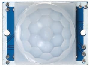
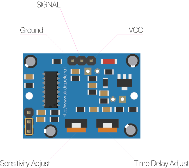
HC-SR501 Sensor
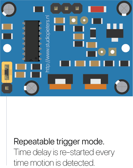
Described security light circuit design is centered around an inexpensive passive infrared (PIR) motion detector module, type HC-SR501. The PIR motion detector module is used here with an added ambient light detection (day/night) feature, supported by a generic photodiode. Following part is prepared to help you get started with your new HC-SR501 passive infrared motion detector module, so let’s start.
Note that imparting the ambient light detection feature involves skillfully combining one photosensitive component and the motion detector electronics with a great deal of dexterity.
Modifying the hardware
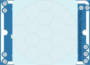
First of all remove the fresnel lens, and search for the “LDR” pads located near the PIR sensor element.
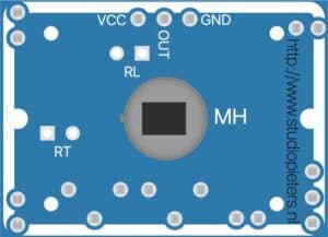
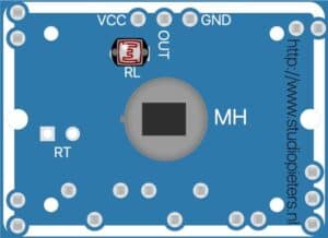
Next, attach a generic LDR (Light-Dependent Resistor) When the light level decreases, the resistance of the LDR increases. As this resistance increases in relation to the other Resistor, which has a fixed resistance, it causes the voltage dropped across the LDR to also increase.
When the solder process is completed, take back the fresnel lens to reseat it, and make sure that everything is found in order.

When the modification is finished, connect HC-SR501 to the rest of the circuit built around discrete components as shown in the circuit diagram. The HC-SR501 requires an initialization time of about 60 seconds, and might become active for 0-3 times during this initialization period. Thereafter HC-SR501 enters in standby mode, and ready for motion detection.
You can adjust the “delay” potmeter clockwise to increase the time delay (3s-300s). Similarly, turning the “sensitivity” pot clockwise increases the detection sensitivity (3-6 metres).
HC SR501 PIR Functional Description
The SR501 will detect infrared changes and if interpreted as motion, will set its output low. What is or is not interpreted as motion is largely dependent on user settings and adjustments.
Device Initialization
The device requires nearly a minute to initialize. During this period, it can and often will output false detection signals. Circuit or controller logic needs to take this initialization period into consideration.
Device Area of Detection
The device will detect motion inside a 110 degree cone with a range of 3 to 7 meters.
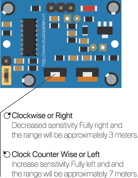
PIR Range (Sensitivity) Adjustment
As mentioned, the adjustable range is from approximately 3 to 7 meters. The illustration below shows this adjustment. You may click to enlarge the illustration.
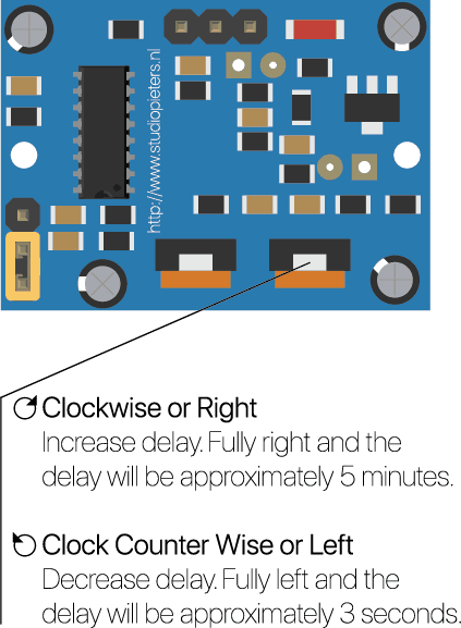
Time Delay Adjustment
The time delay adjustment determines how long the output of the PIR sensor module will remain high after detection motion. The range is from about 3 seconds to five minutes. The illustration below shows this adjustment.
3 Seconds Off After Time Delay Completes – IMPORTANT
The output of this device will go LOW (or Off) for approximately 3 seconds AFTER the time delay completes. In other words, ALL motion detection is blocked during this three second period.
For Example:
- Imagine you’re in the single trigger mode (see below) and your time delay is set 5 seconds.
- The PIR will detect motion and set it high for 5 seconds.
- After five seconds, the PIR will sets its output low for about 3 seconds.
- During the three seconds, the PIR will not detect motion.
- After three seconds, the PIR will detect motion again and detected motion will once again set the output high and the output will remain on as dictated by the Time Delay adjustment and trigger mode selection.

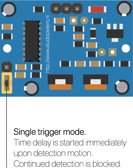
Trigger Mode Selection Jumper
The trigger mode selection jumper allows you to select between single and repeatable triggers. The affect of this jumper setting is to determine when the time delay begins.
- SINGLE TRIGGER – The time delay begins immediately when motion is first detected.
- REPEATABLE TRIGGER – Each detected motion resets the time delay. Thus the time delay begins with the last motion detected.
Enclosure
If you’re a maker, designer or an engineer, chances are you’ll need to make a custom enclosure at some point. This might be a simple container to keep small items organized or a fully functional prototype as I made here in the past. With Autodesk®Fusion 360 software and a desktop 3D printer, you can create a custom snap fit enclosure.

PREPARE YOUR CUSTOM ENCLOSURE DESIGN
For this project, we’re going to make a case, for the HC-SR501 Sensor. I use AutoCAD Fusion 360 because of its popularity in product design and engineering, but you can use a similar 3D design software. First, use digital calipers or a ruler to measure your electronic component in real life. You can then start enclosure designs by accurately reverse-engineering the PCB, measuring the board size, the location of mounting holes, and any ports or plugs that will need to be accessed through the enclosure.
You might want to simply measure the overall maximum dimensions as a box, but it’s essential to know exactly where the main features are so that you can accommodate them. In AutoCAD Fusion 360, reproduce these measurements as a grouping of basic boxes in a single part file.
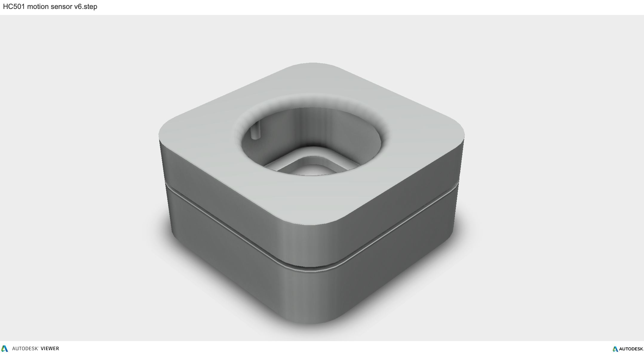
THE BOTTOM ENCLOSURE
In AutoCAD Fusion 360, the snap fit enclosure is best designed as an assembly, with each half of the enclosure modelled as a separate part. Starting with the base half of the enclosure as a new part, the first important decision is to determine how much of a tolerance to have between the perimeter of the PCB and the enclosure. 3D printers are highly accurate, so you can tighten the tolerance to 0.5 mm without much risk. An FDM printer may warp your design and lift it off of the print plate, so you should allow a larger tolerance of 1.5-2 mm to ensure that the PCB will still fit inside even if the walls are somewhat distorted.Add space between the perimeter of your electronic component and the enclosure. Build the walls of the bottom enclosure in your 3D model.
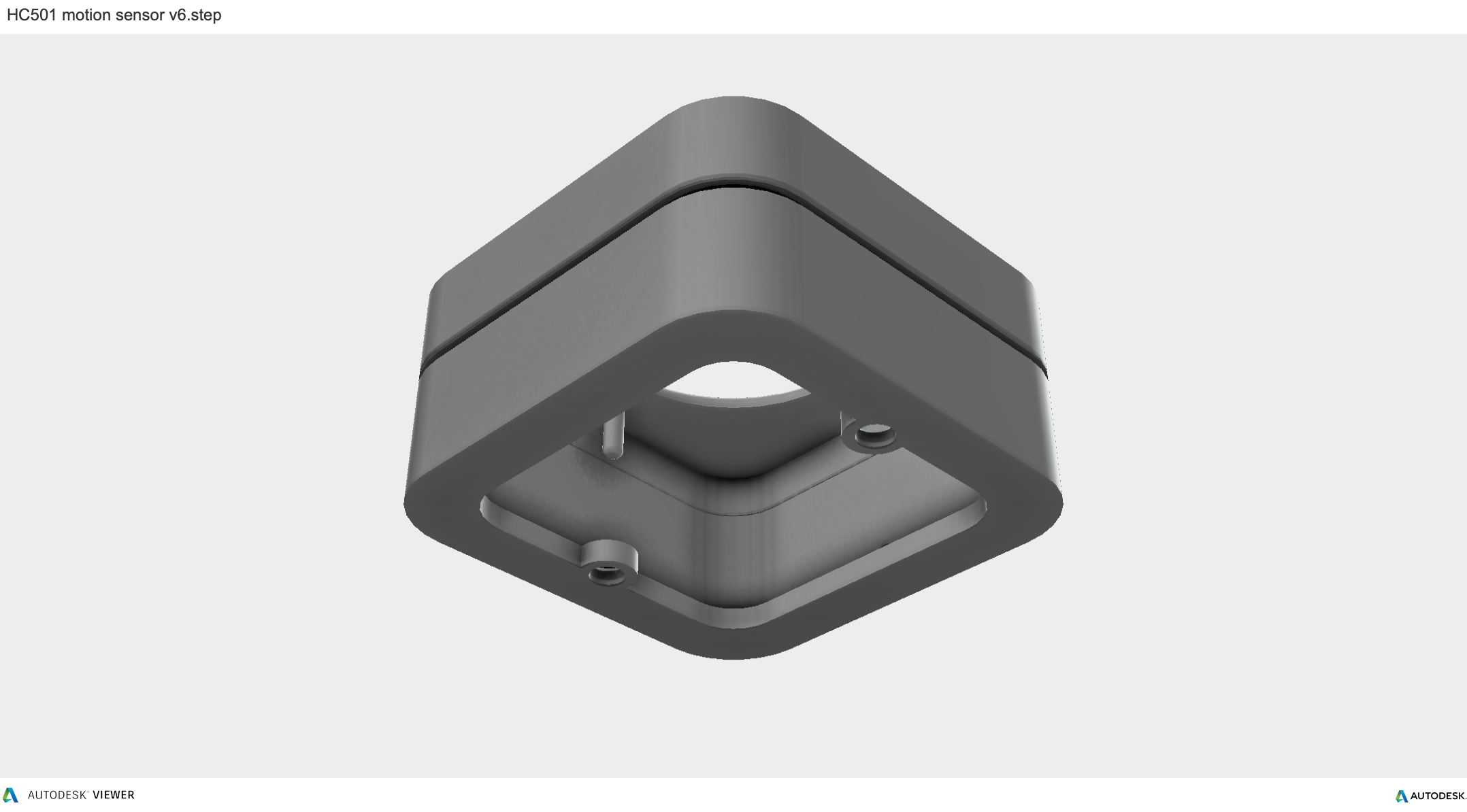
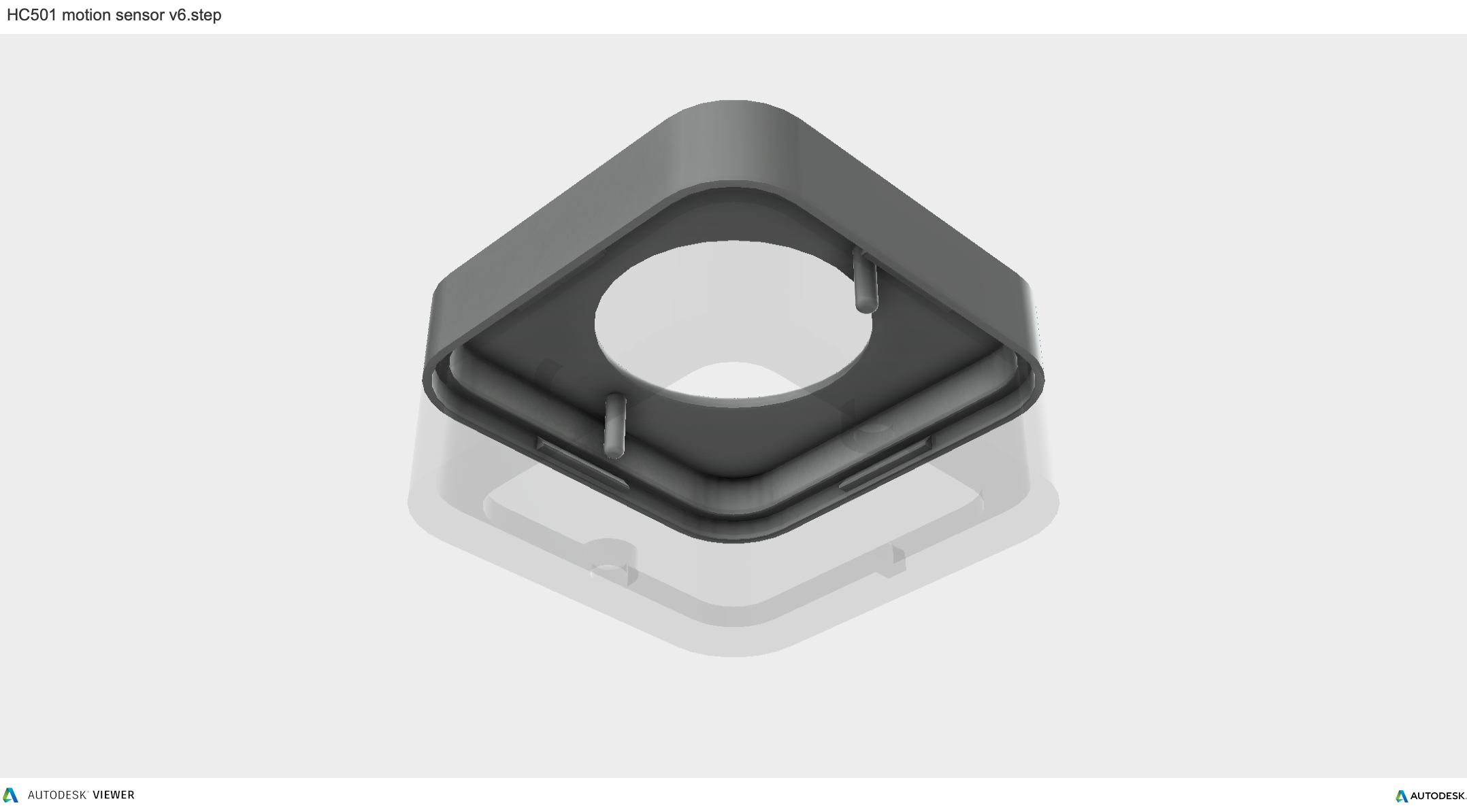
THE TOP ENCLOSURE
In general, the top snap fit enclosure mirrors the geometry of the bottom snap fit enclosure. Now that you’ve completed the bottom t enclosure, the top section is easy. The above image shows the effect of the parting line running around the perimeter between the two enclosure halves. The top snap fit enclosure has had the same treatment of cut details to accommodate some of the taller ports, as well as the addition of material to close off some of the gaps left by the bottom enclosure. We also added an optional sunken middle section.

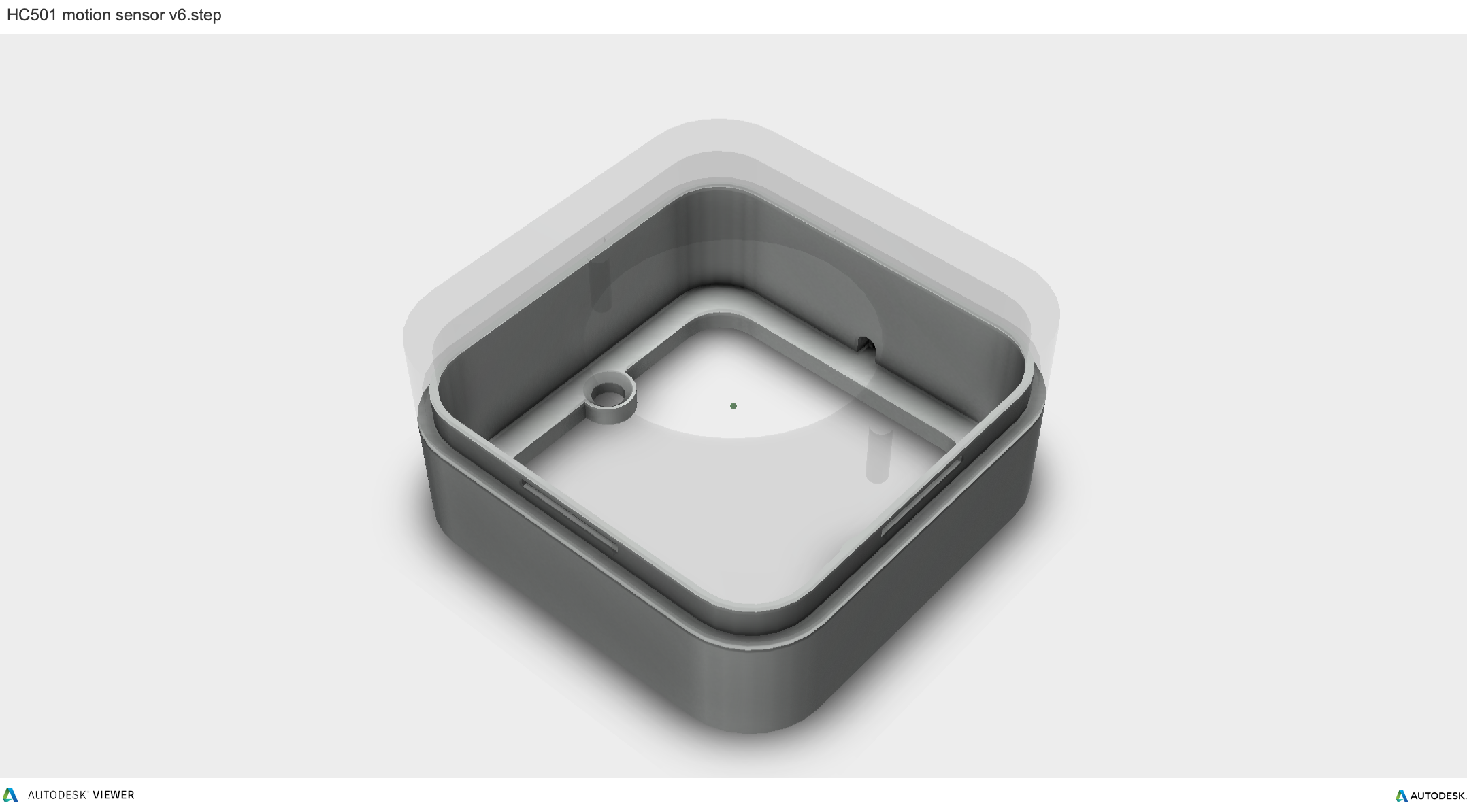
THE SNAP DETAIL
With a basic internal cantilever snap, you can lengthen the amount of plastic engaging into the snap for a stronger lock. There are many designs for snaps, but we opted for a basic internal cantilever. Above you can see the main details for the snap design, which is exactly the same on both sides of the snap fit enclosure. Depending on the space you have to work with, you can lengthen the amount of plastic engaging into the snap cavity to create a stronger lock. Ours is only 1.2 mm, but 2 mm or more would be much more secure. In this particular design, the pins on the PCB take up a lot of room, so the lock is designed to just squeeze in while providing enough force to hold the snap fit enclosure together. The snap detail is extruded 20 mm long, which adds to the strength. This sectioned exploded view shows the snap details on each side.
You can download the files at GrabCAD of at Thingsiverse.


DO YOU HAVE ANY QUESTIONS? LEAVE A COMMENT DOWN HERE.
REFERENCE
T.K. HAREENDRAN, Night Security Light with Hacked PIR sensor, https://www.electroschematics.com/night-security-light-with-hacked-pir-sensor/