For a new ESP HomeKit project I need a Motion Sensor. There are Serveral options out there, but the most common ist the HC-SR501 Passive Infrared (PIR) Motion Sensor. Becuase there is more to it than just sense motion, I gonna explain the fuctions from this little device.

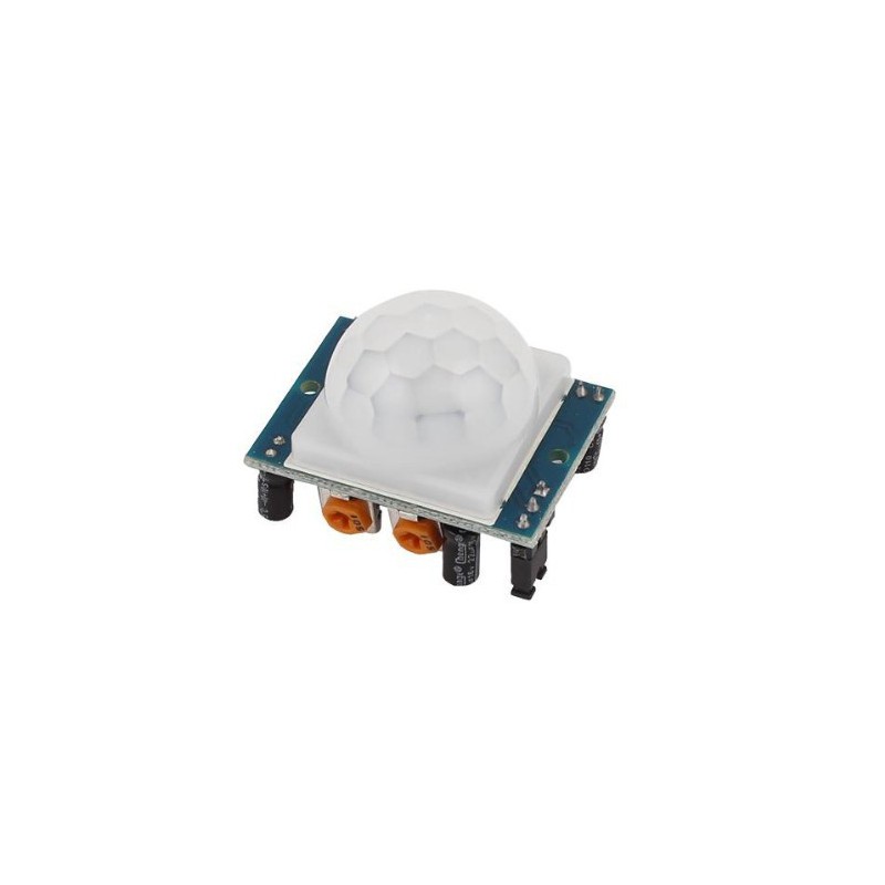
The HC-SR501 Passive Infrared (PIR) Motion Sensor
This motion sensor module uses the LHI778 Passive Infrared Sensor and the BISS0001 IC to control how motion is detected. The module features adjustable sensitivity that allows for a motion detection range from 3 meters to 7 meters. The module also includes time delay adjustments and trigger selection that allow for fine tuning within your application. This article discusses these various functions and demonstrates how to integrate them for use with your Arduino.
HC-SR501 Pin Outs and Controls
The pin-outs and controls for this device are shown in the picture below and described in the following table.
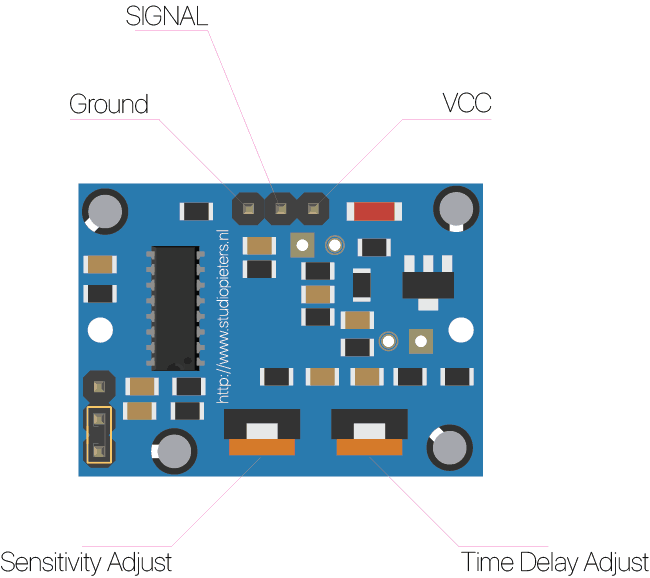
| Pin or Control | Function |
| Time Delay Adjust | Sets how long the output remains high after detecting motion…. Anywhere from 5 seconds to 5 minutes. |
| Sensitivity Adjust | Sets the detection range…. from 3 meters to 7 meters |
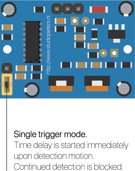
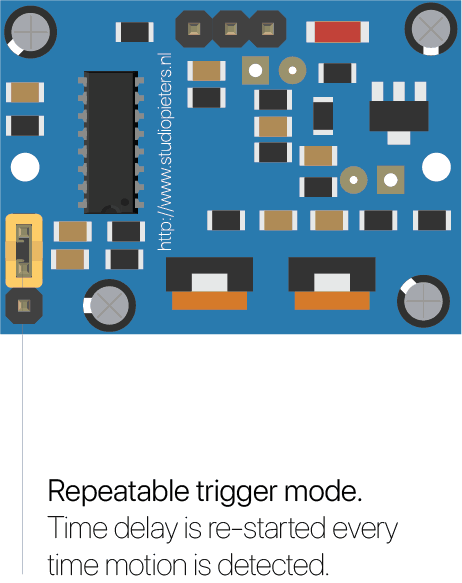
| Trigger Selection Jumper | Set for single or repeatable triggers. |
| Ground pin | Ground input |
| Output Pin | Low when no motion is detected.. High when motion is detected. High is 3.3V |
| Power Pin | 5 to 20 VDC Supply input |
HC SR501 PIR Functional Description
The SR501 will detect infrared changes and if interpreted as motion, will set its output low. What is or is not interpreted as motion is largely dependent on user settings and adjustments.
Device Initialization
The device requires nearly a minute to initialize. During this period, it can and often will output false detection signals. Circuit or controller logic needs to take this initialization period into consideration.
Device Area of Detection
The device will detect motion inside a 110 degree cone with a range of 3 to 7 meters.
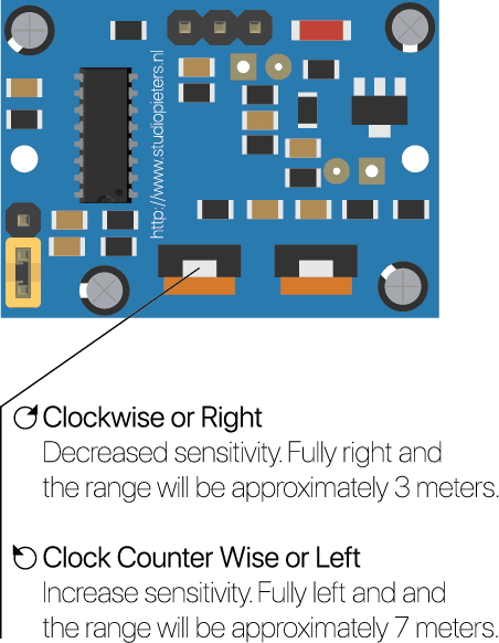
PIR Range (Sensitivity) Adjustment
As mentioned, the adjustable range is from approximately 3 to 7 meters. The illustration below shows this adjustment. You may click to enlarge the illustration.
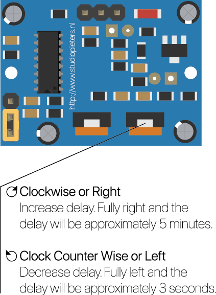
Time Delay Adjustment
The time delay adjustment determines how long the output of the PIR sensor module will remain high after detection motion. The range is from about 3 seconds to five minutes. The illustration below shows this adjustment.
3 Seconds Off After Time Delay Completes – IMPORTANT
The output of this device will go LOW (or Off) for approximately 3 seconds AFTER the time delay completes. In other words, ALL motion detection is blocked during this three second period.
For Example:
- Imagine you’re in the single trigger mode (see below) and your time delay is set 5 seconds.
- The PIR will detect motion and set it high for 5 seconds.
- After five seconds, the PIR will sets its output low for about 3 seconds.
- During the three seconds, the PIR will not detect motion.
- After three seconds, the PIR will detect motion again and detected motion will once again set the output high and the output will remain on as dictated by the Time Delay adjustment and trigger mode selection.
Trigger Mode Selection Jumper
The trigger mode selection jumper allows you to select between single and repeatable triggers. The affect of this jumper setting is to determine when the time delay begins.
- SINGLE TRIGGER – The time delay begins immediately when motion is first detected.
- REPEATABLE TRIGGER – Each detected motion resets the time delay. Thus the time delay begins with the last motion detected.
HC-SR501 Motion Application Examples
Imagine that you want to control lighting in your garden as sombody walks into the garden. Understanding how the time delay and trigger mode interact will be necessary to controlling that lighting in the manner that you want.
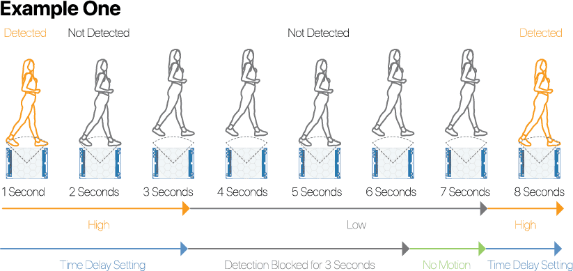
Example One
In this first example, the time delay is set to three seconds and the trigger mode is set to single. As you can see in the illustration below, the motion is not always detected. In fact, there is a period of about six seconds where motion can not be detected.
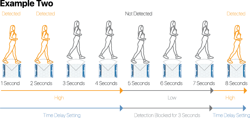
Example Two
In the next example, the time delay is still at three seconds and the trigger is set to repeatable. In the illustration below, you can see that the time delay period is restarted. However, after that three seconds, detection will still be blocked for three seconds.
As I mentioned previously, you could override the 3 second blocking period with some creative code, but do give that consideration. Some of the electronics you use may not like an on and then off jolt. The three seconds allows for a little rest before starting back up.
So as you can see there’s more to it than just sensing a motion.
REFERENCE
Henry’s Bench, Arduino HC-SR501 Motion Sensor Tutorial, http://henrysbench.capnfatz.com/henrys-bench/arduino-sensors-and-input/arduino-hc-sr501-motion-sensor-tutorial