Are you tinkering with electronics, trying to program microcontrollers, or perhaps diving into the realm of embedded systems? If so, you might have come across the FT232RL programmer module, a tiny but powerful tool that facilitates communication between your computer and various electronic devices. But what exactly are those pins on the module, and what do they do? Fear not, for we’re here to demystify the pinout of this nifty little gadget in a simple and straightforward manner.

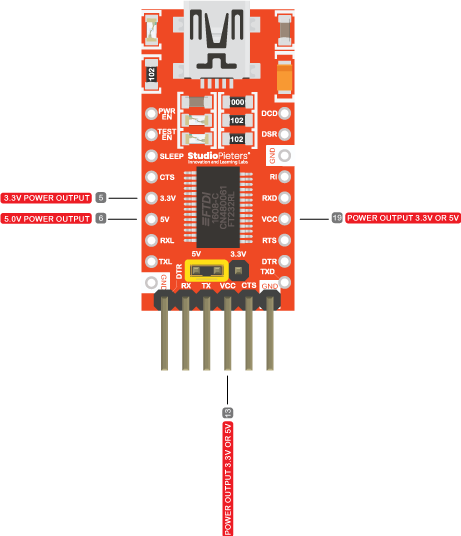
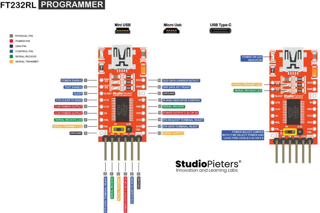
1. VCC (Pin 1): This pin provides power to the module. Connect it to a suitable voltage source, usually 5V.
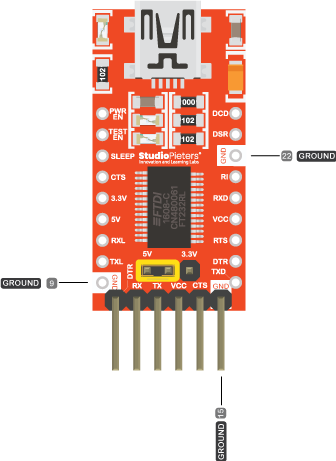
2. GND (Pin 2): Ground connection – essential for completing the circuit and ensuring stable operation.
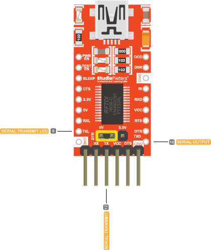
3. TXD (Pin 3): Transmit Data. This pin sends data from the module to the connected device or microcontroller.
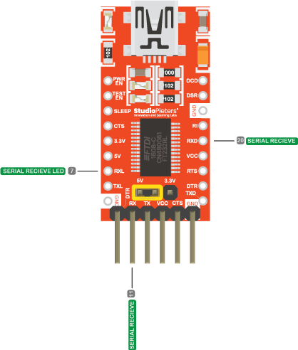
4. RXD (Pin 4): Receive Data. Data received from the connected device or microcontroller is received through this pin.
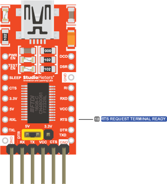
5. RTS (Pin 5): Request to Send. This pin is used in flow control mechanisms, typically hardware flow control.
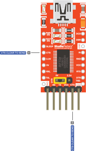
6. CTS (Pin 6): Clear to Send. It indicates whether the device connected to the module is ready to receive data.
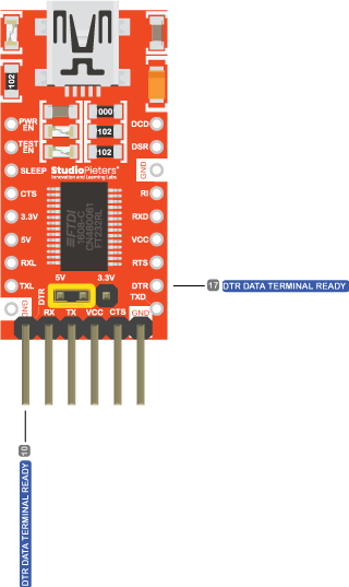
7. DTR (Pin 7): Data Terminal Ready. This pin signals to the connected device that the module is ready to communicate.
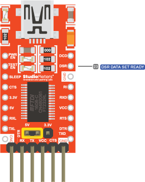
8. DSR (Pin 8): Data Set Ready. It indicates that the module is ready to receive data from the connected device.
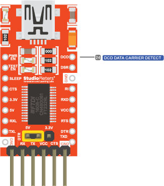
9. DCD (Pin 9): Data Carrier Detect. This pin detects the presence of a carrier signal from the connected device.
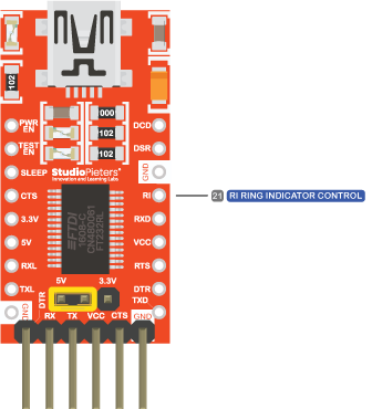
10. RI (Pin 10): Ring Indicator. Typically used in serial communication to indicate an incoming call or signal.
That’s the basic rundown of the FT232RL programmer module’s pinout. But what about those other pins you might spot on the PCB? Let’s take a quick peek:

Additional Pins
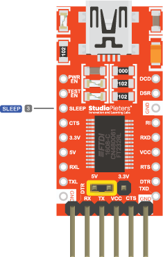
11. SLEEP (Pin 11): This pin allows the module to enter a low-power sleep mode when not in use, conserving energy.
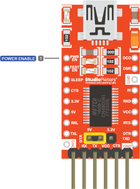
12. PWREN# (Pin 12): Power Enable. It controls the power to the external circuitry.
13. CBUS0 – CBUS3 (Pins 13-16): Configurable I/O Pins. These can be programmed for various purposes depending on your specific application needs.
And there you have it, folks! The FT232RL programmer module pinout laid bare for all to see. So, the next time you’re puzzling over which pin goes where, just remember this simple guide. Happy tinkering!
Remember, when in doubt, just follow the golden rule of electronics: when all else fails, read the datasheet!