Say if you have a sensor that is supplying a voltage that is much higher than you may need for a particular part of a circuit, such as for a chip in the circuit in this case a ESP8266. The sensor is run off of a 5.0V supply but the chip (ESP8266) in the circuit only needs 3.3V. So we need something that’s called a Voltage Divider.
Method #1 – Voltage Divider
It turns out, there are many ways of doing so, and one of the easiest and cheapest ways of doing so is simply using resistors. With resistors, we can form a voltage divider circuit, so that we can obtain any voltage we want. To know how to reduce voltage, you simply just have to understand how the math works for voltage divider circuits, and we will go over this below. Through this technique, you can take any voltage and lower it to any level you want. This is very useful if you want to connect an Sensor, that operates at 5V, to an ESP8266 that operates at 3.3V. There are two methods to do this.

Reduce Voltage in Half
To reduce voltage in half, we simply form a voltage divider circuit between 2 resistors of equal value (eg 2 x 10KΩ) resistors.
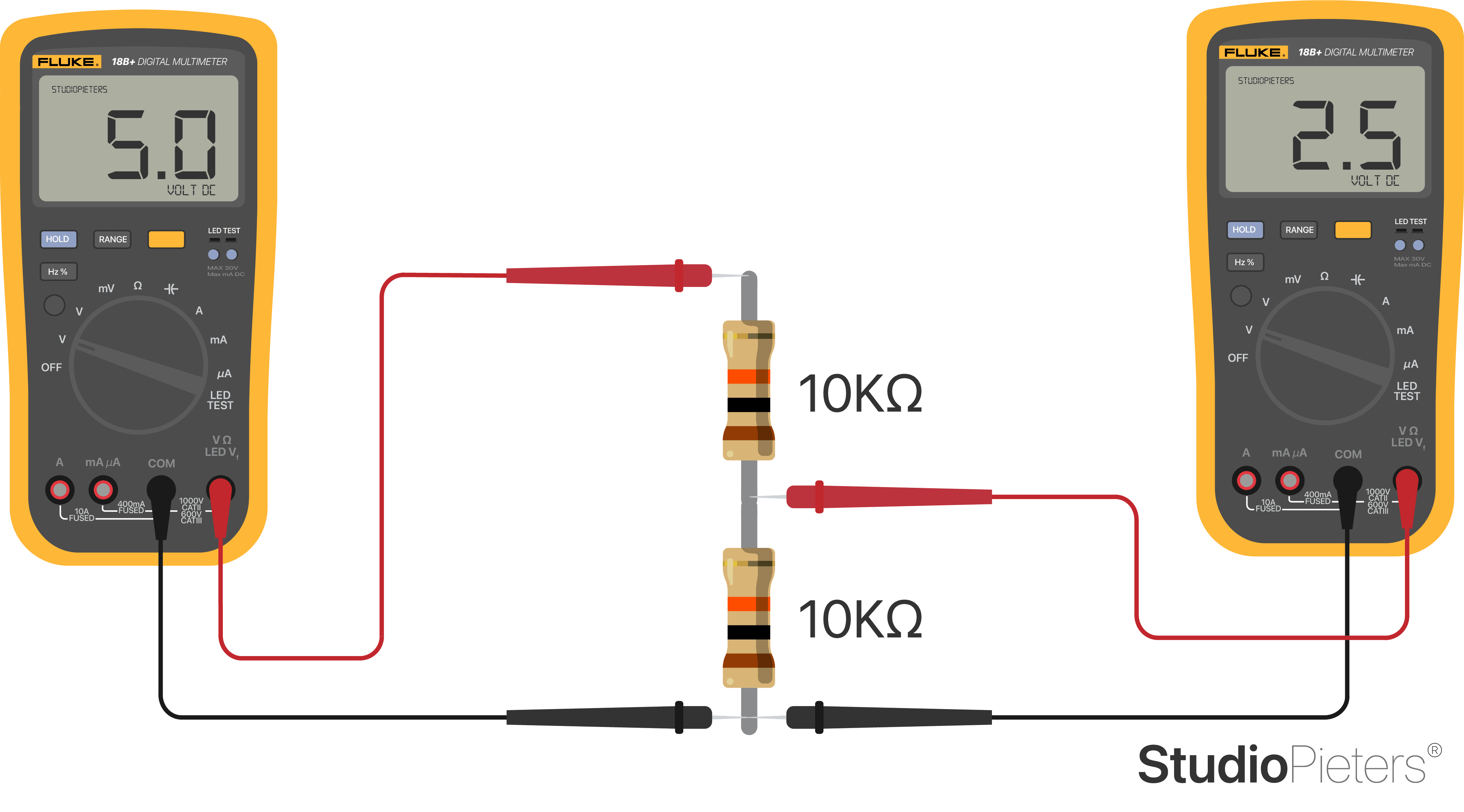
To divide voltage in half, all you must do is place any 2 resistors of equal value in series and then place a jumper wire in between the resistors. At this point where the jumper wire is placed, the voltage will be one-half the value of the voltage supplying the circuit. The 5.0V is now 2.5V. VCC is split in half.
Reduce the Voltage to Any Value
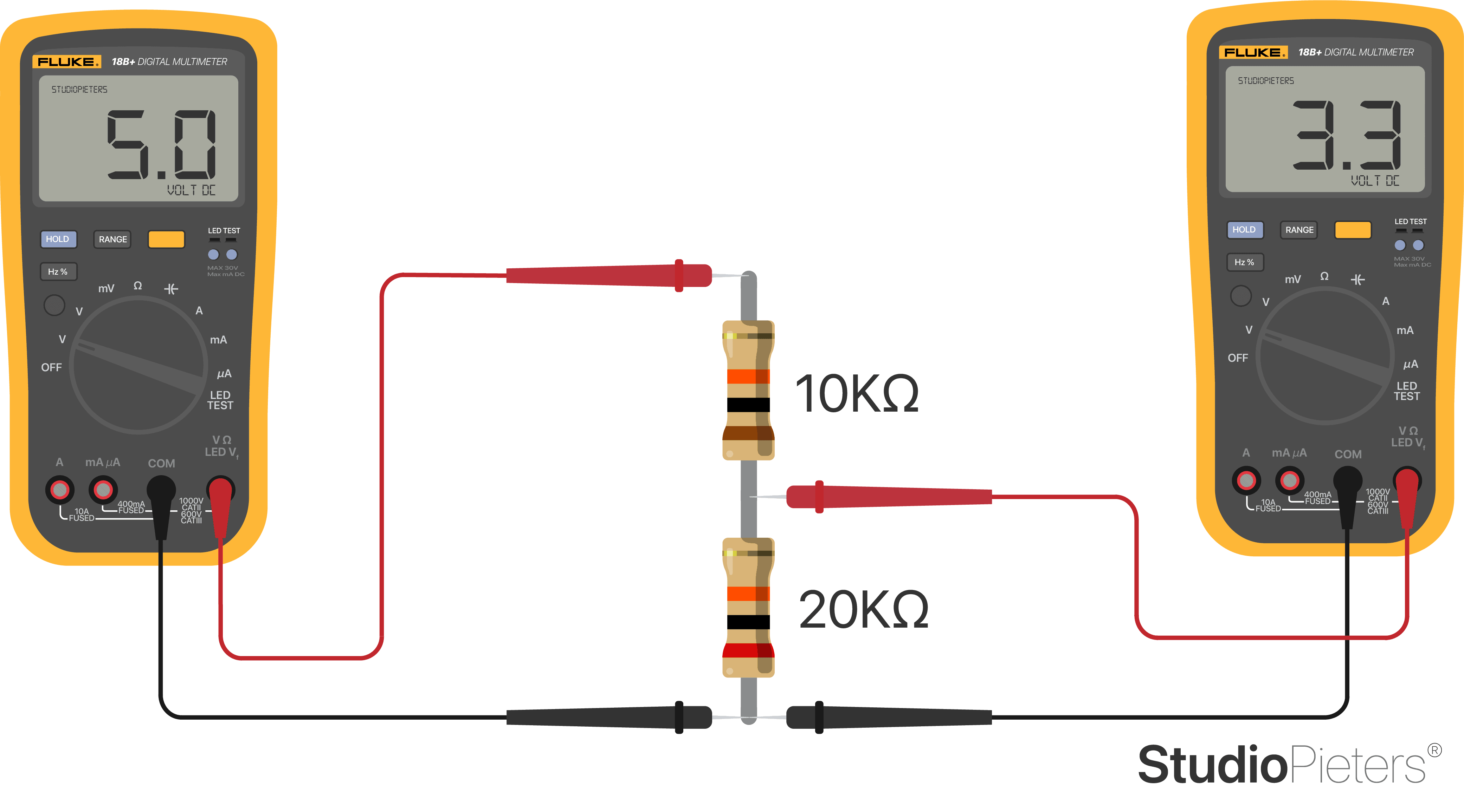
You may not always want half the voltage, but you can get the voltage to any level you want choosing the appropriate resistor values for a voltage divider circuit. Maybe your circuit is running off of 5V, yet you want only 3V to feed into a particular circuit element. How can you get the 5 volts into 3V? And you can do so with the correct resistor values in a voltage divider circuit.

Calculation
The formula for calculating the voltage that falls across the R2 resistor is shown below. But this formula, in its original form, does not help us in finding the resistor R2 we need for getting a particular voltage. Rearranging this formula and solving for R2 yields the formula below.
Default Formula:
| VOUT = VIN | R2 |
| R1 + R2 |
We fill in all variables we have:
| 3.3V = 5.0V • | R2 |
| 10KΩ + R2 |
Reformulate:
| 10KΩ + R2 = | 5.0V | R2 |
| 3.3V |
As you can see the values 5 and 1 are derived from 5V¹ and (10KΩ / 10)².
| 10KΩ = | ( | 5.0V | R2 | ) | – R2 = | 5 ¹ | R2 |
| 3.3V | 1² |
This will give us:
| R2 = | 1² | • 10KΩ |
| 5¹ |
With as end result:
| R2 = | 20KΩ |
Check by plugging , back into the voltage divider equation:
| 5.0V | 20KΩ | 5.0V • | 20KΩ | 3.3V |
| 10KΩ + 20KΩ | 30KΩ |

This is the formula we can use for choosing the resistor value we need to get any voltage we want. So back to our circuit, if we have 5V and want 3.3V from it, we use the formula above.
Warning: This method works for slow signals. For complicated communication I recommend using Method #2.
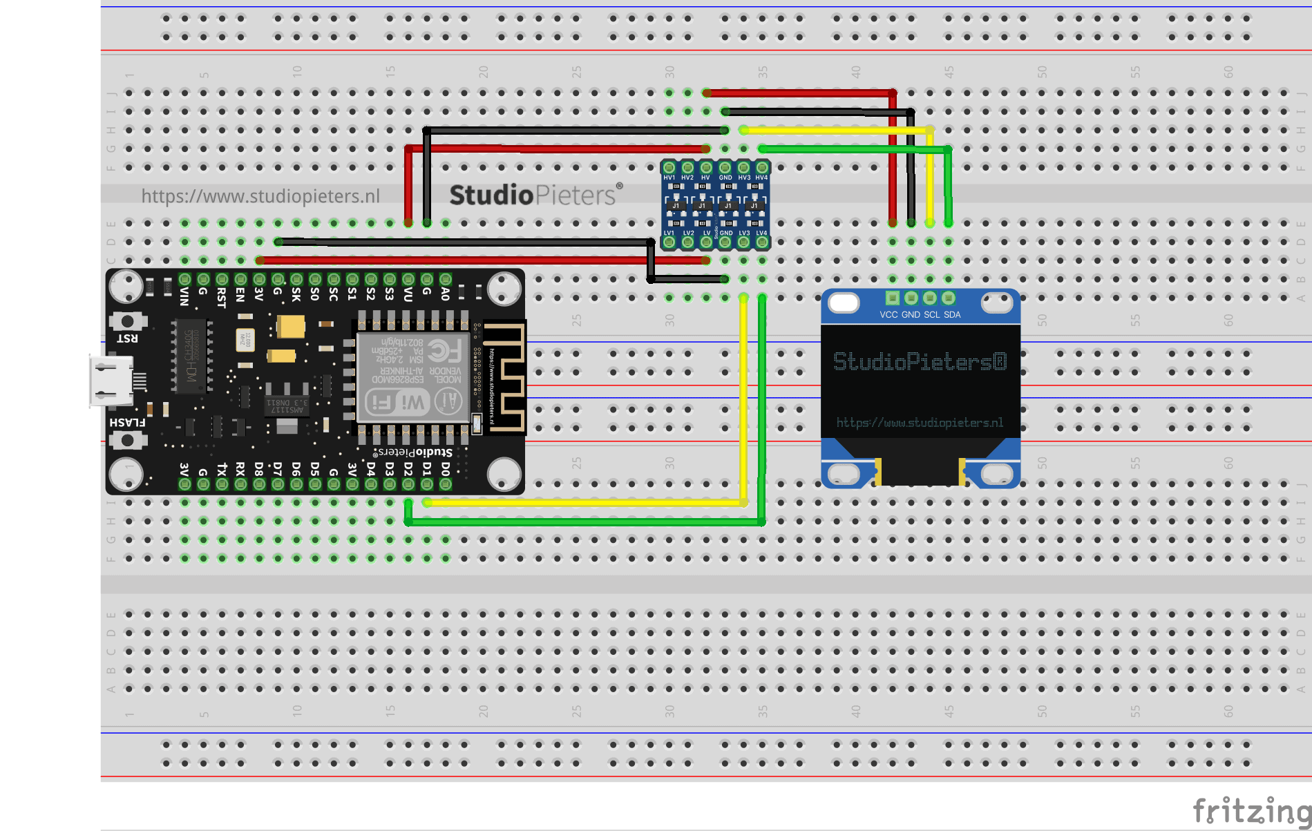
Method #2 – Bi-Directional Logic Level Converter
A Bi-Directional Logic Level Converter (LLC) also reduces the voltage from a signal. This the recommended method to level shift signals that require high speed communication (serial at a high baud rate, I2C, etc…).
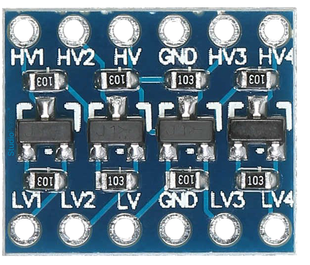
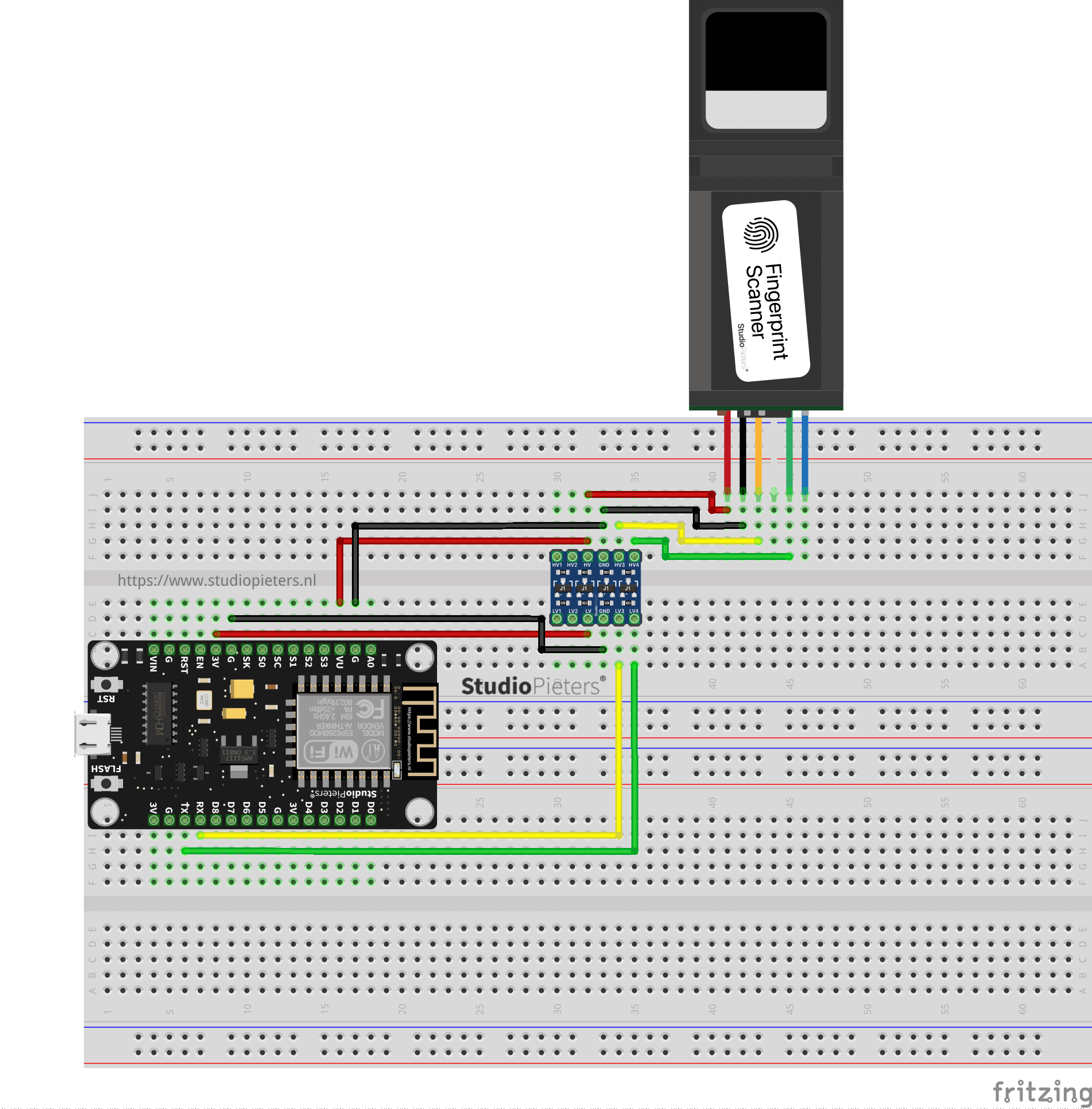
You simply connect the signal with the High Voltage to the HV pins and it outputs the signal with the Lower Voltage on the other side (LV). With the board shown in the image above you have 4 channels available. Though they’re share the same shape and size, this bi-directional logic level converter shouldn’t be confused with the more “uni-directional” version. This converter can pass data from high to low and / or low to high on all channels. It’s perfect for level-shifting between devices that are sharing a data wire, like I2C or a one-wire interface.

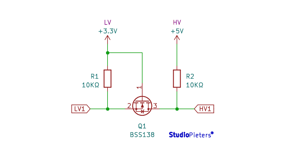
Scheme
If you take a peek at the board’s schematic, you’d find that the bi-directional logic level converter (let’s shorten that to BD-LLC) is actually a very simple device. There is basically one level-shifting circuit on the board, which is repeated four times to create four level-shifting channels. The circuit uses a single N-channel MOSFET and a couple pull-up resistors to realize bi-directional level shifting.
Bi-Directional Logic Level Converter for Serial
Although you won’t be taking advantage of the Bi-Directional Logic Level Converter, bi-directional abilities, it’s perfectly fine to use the board to shift serial communication. Serial usually requires two signal wires, RX (receive) and TX (transmit), which both have a defined direction. These signals can be passed through any of the four channels on the Bi-Directional Logic Level Converter
Bi-Directional Logic Level Converter for SPI
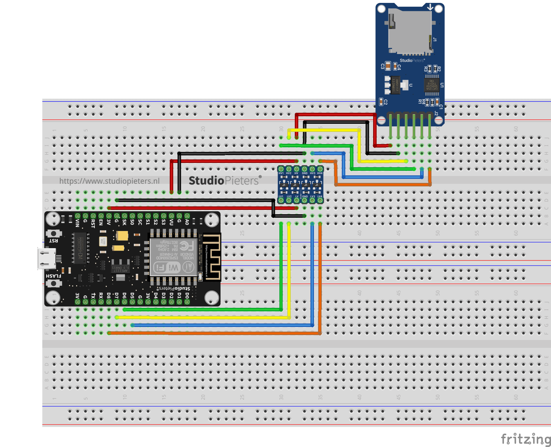
The Bi-Directional Logic Level Converter four channels are a perfect match for most SPI communications. SPI usually requires four wires: MOSI (master out, slave in), MISO (master in, slave out), SCLK (serial clock), and CS (chip select). These four wires can each be routed through a channel on the Bi-Directional Logic Level Converter.
Bi-Directional Logic Level Converter for I2C
I2C is the communication standard where the Bi-Directional Logic Level Converter really shines, because it requires that both data and clock signals, SDA and SCL, be bi-directional. Each of those lines can be passed through any of the Bi-Directional Logic Level Converter level-shifting channels.