
Electronics
More Pins for an ESP8266 with an MCP23017
A test setup that adds 16 pins to an ESP8266 with an MCP23017 I/O expander on I2C, with a led as the example.
- ESP8266
- 1 min read
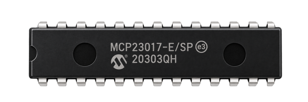
An ESP8266 does not have many pins that you can use freely. This test setup adds 16 more with an MCP23017, an I/O expander that the ESP8266 controls over I2C. A led on one of the new pins is the example: it is switched on and off through the expander.
Why an expander
Every project on this site that needs more inputs or outputs than the module has runs into the same limit. The MCP23017 gives 16 pins over two wires, so a small ESP8266 can drive many leds, relays or buttons. The MCP23017 I/O expander guide describes the chip in detail: its pins, its I2C address and its registers.
The circuit
| Part | What it does |
|---|---|
| ESP-12 module | The ESP8266, programmed with the FTDI adapter |
| MCP23017 | The expander, connected to the ESP8266 over I2C |
| Led with a resistor | The example, on one of the expander pins |
| RESET and PROGRAM buttons | For programming the module |
| FTDI adapter | Powers the setup and programs the module |
The I2C connection uses two wires, one for the clock (SCL) and one for the data (SDA). In the Arduino core for the ESP8266, the default pins for I2C are GPIO4 for SDA and GPIO5 for SCL. Follow the wires in the diagram for your own build.
Use it
The expander has two ports of eight pins each. The led shows the basic use: set a pin of the expander as an output, and switch it on or off from the ESP8266, exactly like a pin of the ESP8266 itself. This is a test setup, made to prove that the expander works with the ESP8266.
Good to know
- The repository holds the diagram and is under the MIT licence. It has no code.
The project is in the ESP8266-MCP23017 repository on GitHub.
Related
 Electronics
Halloween Jack O’ Lantern V2
After the success of my previous project, the Halloween, Jack O’ Lantern – many of you asked for something even more dynamic, with smoother flame transitions and more LED action.
Read more
Electronics
Halloween Jack O’ Lantern V2
After the success of my previous project, the Halloween, Jack O’ Lantern – many of you asked for something even more dynamic, with smoother flame transitions and more LED action.
Read more
 Electronics
RGB Light with an ESP8266 and Homebridge
An ESP8266 that drives an RGB light with PWM and answers the web requests of the homebridge-http-rgb-push plugin.
Read more
Electronics
RGB Light with an ESP8266 and Homebridge
An ESP8266 that drives an RGB light with PWM and answers the web requests of the homebridge-http-rgb-push plugin.
Read more
 Papercraft
The Stormtrooper Helmet: Pepakura Files for a Star Wars Fan
A Star Wars fan's papercraft collection, built around the First Order Stormtrooper helmet and the full armour, with more helmets and figures.
Read more
Papercraft
The Stormtrooper Helmet: Pepakura Files for a Star Wars Fan
A Star Wars fan's papercraft collection, built around the First Order Stormtrooper helmet and the full armour, with more helmets and figures.
Read more
More projects
Keep building.
Electronics, 3D printing and CNC builds, documented from the first idea to the last screw.
All projects