The I²C bus communication is one out of three possible communication protocols, the ESP8266 is able to communicate with other devices like OLED displays, barometric pressure sensors and so on. The two other communication protocols are SPI and UART. I²C stands for Inter-Integrated Circuit was invented 1982 by Philips Semiconductor (A Dutch company), now NXP Semiconductors.

I²C BUS features
I²C has multiple features which are also compared in the following table:
- Synchronous: The output of bits is synchronized to the sampling of bits by a clock signal shared between the master and the slave.
- Multi-master: You can have multiple masters controlling single, or multiple slaves.
- Multi-slave: You can connect multiple salves to a single master like SPI.
- Packet switched: The transferred data is grouped in packages / messages, made of a header and a payload.
- Single-ended: The data is transferred by a single wire.
- Serial connection: Data is transferred bit by bit along a single wire
I²C reference design with timing diagram
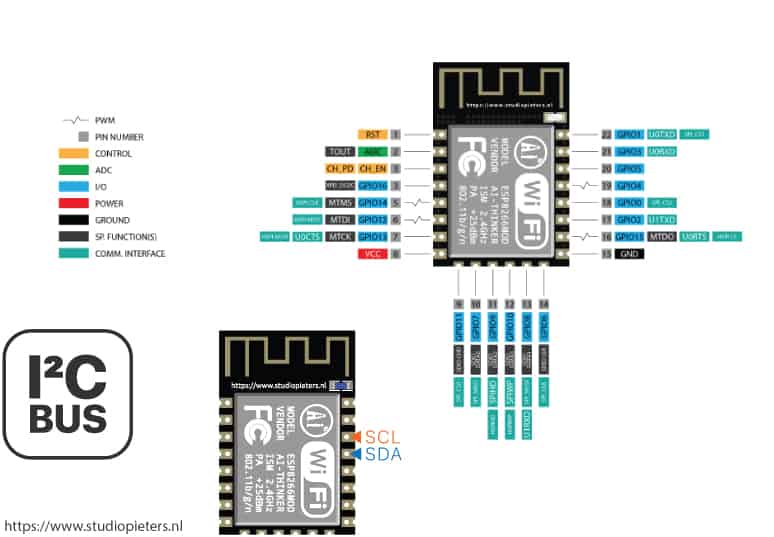
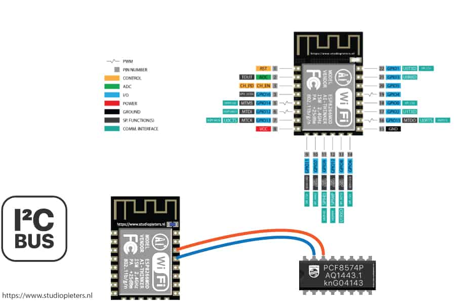
On your ESP8266 you will find two GPIO’s (SDA and SCL) for the I²C communication. If you are not sure were to find the corresponding pins, see the following pictures or for the complete pinout.
ESP8266 12F
SDA: GPIO4 ( I²C -> Data)
SCL: GPIO5 ( I²C -> Clock)
I²C communication
The two pins which you need for the I²C communication are the following, SDA (Serial Data): Connection between master and slave to send and receive data. SCL (Serial Clock): Shares the clock signal between the master and the slave, where the master always controls the clock signal.
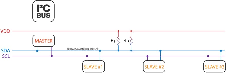
The Serial Data line and the Serial Clock line are pulled up with resistors. Therefore when there is no transmission of data on the bus, the SDA and SCL are in the HIGH state. Why a resistor is needed, see subsection “Physical layer”. Typical voltages are +5V and +3.3V and devices can communicate at 100 kHz or 400 kHz. All I²C devices are connected to the bus either with open collector or open drain pins to pull the line LOW. The communication between master and slave occurs by toggling the lines by pulling LOW and releasing HIGH. Also bits are clocked on falling clock edges.

There may be four potential modes of operation for a given bus device, although most devices only use a single role and its two modes:
- master transmit – master node is sending data to a slave,
- master receive – master node is receiving data from a slave,
- slave transmit – slave node is sending data to the master,
- slave receive – slave node is receiving data from the master.
I²C Message Protocol
The I²C message protocol is divided bit by bit into fixed sections. We will take a closer look at the six different sections of the protocol.
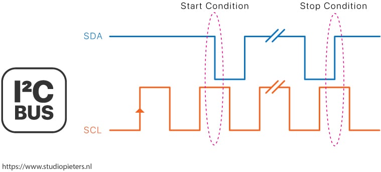
Start condition: SDA: HIGH → LOW while SCL is HIGH
Stop condition: SDA: LOW → HIGH while SCL is HIGH
Note: The start and the stop condition are the only two times in the whole I²C communication, where the SDA line changes when the SCL line is HIGH. In all other conditions the SDA line only changes state when the SCL line is LOW.
- Address Frame: The address frame is a 7 or 10 bit sequence to identify each slave for the master. The identifier is unique over all slaves. Each slave compares the address sent from the master to its own address. If the address matches, it sends a ACK bit → 0 back to the master. If the address doesn’t match, the slave does nothing and the SDA line remains high.
- Read/Write Bit
Write: Master is sending data to the slave: 0
Read: Master is requesting data from the slave: 1 - ACK/NACK Bit. If an address frame or data frame was successfully received, an ACK bit → 0 is returned to the sender from the receiving device.
- Data Frame: After the master detects the ACK bit from the slave, the first data frame is ready to be sent. The data frame is always 8 bits long and is followed by an ACK/NACK bit to verify that the frame has been received successfully. The master will continue generating clock pulses at a regular interval.
Note: Because after every Data Frame a ACK /NACK bit is transferred, the I²C communicate protocol has a data overhead.
It is possible for the master to exchange several messages in one go, without allowing an other master device take control over the bus. Therefore a repeated start condition is defines as the following:
SCL 0 → 0
SDA 0 → 1
SCL 0 → 1
SDA 1 → 0
Note that there was not Stop condition.
Clock stretching
In some cases the masters data rate will be exceed the slaves ability to provide the requested data. Therefore the slave can hold down the SCL line after the master releases the SCL line. The master will wait for the click line to be released by the slave before proceeding to the next frame.
Physical Layer
Unlike UART or SPI connections, the I²C bus drivers are “open drain”, meaning that they can pull the corresponding signal line low, but cannot drive it high. Therefore, there can be no communication where one device is trying to drive the line high while another tries to pull it low. This architecture avoids errors in the communication.
But how is it possible to pull the signal line high? Each signal line has a pull-up resistor to restore the signal to high when no device is asserting the line to low. A rule of thumb picking a resistor is 4.7 kΩ. The more devices are connected to the I²C communication the smaller has to be the resistor.
I²C allows for some flexibility in connecting devices with different I/O voltages. For an Arduino board with a voltage level of 5V as master, a slave of 3.3V will be work without problems. But if the voltage of the slave will be lower than 3.3V for example 2.5V there is the possibility to buy a I²C level shifter board.

I²C Speed Modes
- Low speed mode: 10 kbit/s
- Standard mode: 100 kbit/s
- Fast mode: 400 kbit/s
- Fast mode plus: 1 Mbit/s
- High speed mode: 3.4 Mbit/s
- Ultra fast mode: 5 Mbit/s
Advantages and Disadvantages of I²C communication
| Advantages | Disadvantages |
| Only uses two wires Supports multiple masters and multiple slaves Well known and widely used protocol |
Slower data transfer rate than SPI The size of the data frame is limited to 8 bits |
I²C Examples
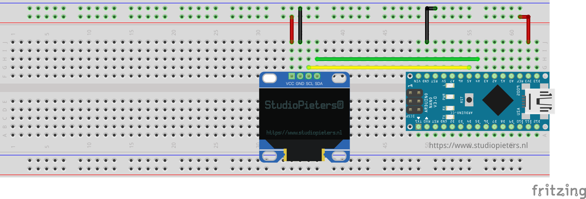
We leave the theory behind us and attend to practical examples. Before we can control an I²C device, we first have to find out its HEX address. Therefore, our first example will be an I²C HEX address scanner. After we found out the HEX address of the I²C LCD display, we will control the display accordingly to send messages from the ESP8266 via I²C to the LCD display.
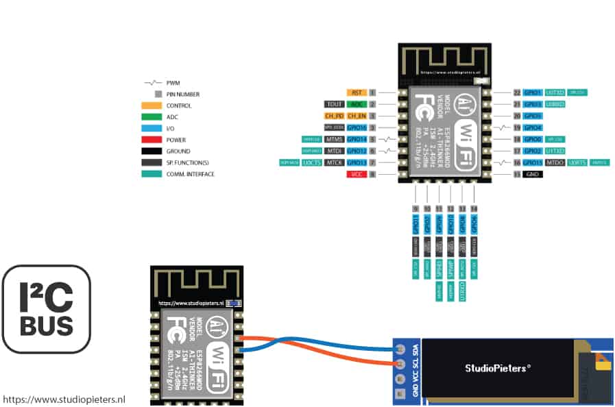
| ESP8266 12F | I²C Oled Display |
| GND | GND |
| VIN | VCC |
| GPIO4 | SDA |
| GPIO5 | SLC |
How to find the HEX Address?
For demonstration purpose we use the Arduino IDE software you can download it here for free.
#include "Wire.h"
The “Wire.h” library allows the micro-controller to communicate with I²C devices. Therefore this library is essential every time you want to use the I²Ccommunication.
void setup(){
Serial.begin(115200);
while(!Serial){} // Waiting for serial connection

Serial.println();
Serial.println("Start I²C scanner ...");
Serial.print("\r\n");
byte count = 0;
This sketch uses only the setup function, because we want only one time to scan all connected devices. First we define the baud rate to 115200 and we will memorize to set the baud rate of the serial monitor to the same value. Than we wait until the serial connection is established that we are able to scan devices. After we define some cool printings on the serial monitor, we define a variable count to zero. The variable will be increased when we find an I²C device and is therefore the sum of connected I²C devices.
Wire.begin();
for (byte i = 8; i < 120; i++)
{
  Wire.beginTransmission(i);
  if (Wire.endTransmission() == 0)
  {
    Serial.print("Found I2C Device: ");
    Serial.print(" (0x");
    Serial.print(i, HEX);
    Serial.println(")");
    count++;
    delay(1);
  }
}
With Wire.begin() the micro-controller joins the I²C bus as master or slave. If no address is provided in the function like Wire.begin(address), the device joins as master like we want. To scan all possible I²C HEX addresses we use a for loop. To begin the transmission to the possible I²C slave we use the Wire.beginTransmission(address) function. If there is a valid I²C slave we get a 0 by ending the transmission to the slave through Wire.endTransmission(). We print the HEX address of the connected device on the serial monitor. Also if we found an I²C device we increase the counter by 1 and use a little delay before trying to connect to the next device.
Serial.print("\r\n");
Serial.println("Finish I2C scanner");
Serial.print("Found ");
Serial.print(count, HEX);
Serial.println(" Device(s).");
}

void loop() {}

At the end of the script we print the total number of found I²C devices. We do not use the loop function. Feel free to copy the whole script in your Arduino IDE.
#include "Wire.h"

void setup() {
  Serial.begin(115200);
  while (!Serial) {} // Waiting for serial connection

  Serial.println();
  Serial.println("Start I2C scanner ...");
  Serial.print("\r\n");
  byte count = 0;

  Wire.begin();
  for (byte i = 8; i < 120; i++)
  {
    Wire.beginTransmission(i);
    if (Wire.endTransmission() == 0)
    {
      Serial.print("Found I2C Device: ");
      Serial.print(" (0x");
      Serial.print(i, HEX);
      Serial.println(")");
      count++;
      delay(1);
    }
  }
  Serial.print("\r\n");
  Serial.println("Finish I2C scanner");
  Serial.print("Found ");
  Serial.print(count, HEX);
  Serial.println(" Device(s).");
}

void loop() {}
If we look at the serial monitor, the result is the following I²C Scanner Serial Output We found the connected I²C LCD display with the HEX address 0x27. We will need this address for our next example.
Control an LCD Display
With the I²C HEX scanner we found out that the HEX address of the LCD display is 0x27. Now we can program the script to communicate with the LCD display. I made already two blogs about I²C OLED displays you can find more information here and here.
I²C Multiplexer
If you want to connect a lot of sensors to your ESP8266 and your normal I²C connection comes to a limit? Maybe the sensors have the same I²C address. The solution to your problem is the PCF8574 1-to-8 I²C expander. The PCF8574 Breakout enables communication with multiple I²C devices that have the same address making it simple to interface with them. PCF8574 is an eight-channel I²C expander which allows eight separate I²C devices to be controlled by a single host I²C bus. The PCF8574 is a 8-bit input/output (I/O) expander for the two-line bidirectional bus (I²C) and designed for operation voltages between 2.5V and 6V. The standby current consumption is very low with 10μA. The PCF8574 is connected to the ESP8266 as follows:
P0…P7 are the P-port input/output with push-pull design structure. Here you connect your I²C devices to the PCF8574. A0…A2 are address inputs for the PCF8574 itself. Click here, if you want to look at the complete datasheet of the PCF8574.

DO YOU HAVE ANY QUESTIONS? LEAVE A COMMENT DOWN HERE.
REFERENCE
diyi0t, https://diyi0t.com/i2c-tutorial-for-arduino-and-esp8266/ , https://diyi0t.com/i2c-tutorial-for-arduino-and-esp8266/