Slowly but surely I am looking at the extensions of the “standard” ESP HomeKit accessories, how to implement them. Now I am working on the Battery status. We need some circuit which can effectively measure voltage. Battery monitoring circuit is a traditional voltage divider circuit. I am going to measure 3.7 volt (lithium Polymer) battery.
Voltage divider working and calculations
ESP8266 is a tiny device, it works on 3.3 volts. Since it is working on 3.3 volts its pins can source and sunk 3.3 volts only. Voltage greater than 3.3 volt may blow the pin or fry the ESP8266. In our case we want to measure 3.7 volt battery and ESP8266-12 ADC (Analog to Digital Channel) can only accept 1.0 volts.
ESP8266 ADC Resolution
The ADC pin has a 10-bit resolution, which means you’ll get values between 0 and 1024. The ESP8266 ADC pin input voltage range is 0 to 1V if you’re using the bare chip. However, most ESP8266 development boards come with an internal voltage divider, so the input range is 0 to 3.3V. So, in summary:
- ADC Voltage range in ESP8266 development boards: 0 to 3.3V (for example: ESP8266 12-E NodeMCU Kit, WeMos D1 Mini, …)
- ADC Voltage range in ESP8266 chip: 0 to 1V (for example: ESP-07 chip, ESP-12E chip, …)
We need to play smartly here. What we will do is divide the voltage between two resistors and measure only voltage across one resistor and remaining resistor voltage will be calculated mathematically. Typical voltage divider circuit and formula is given below.
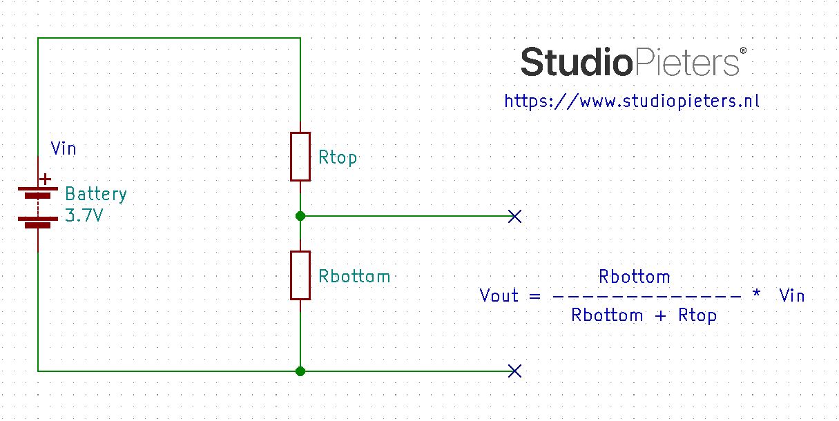
Now lets calculate the values for Rtop and Rbottom. Here we need some important considerations to be taken seriously.
- Low ohm resistors can sunk much current and wires could be heated instantly. Consequently wires can melt down in seconds. So always use sufficient amount of resistors for bigger ampere hour batteries. I selected one resistor Rbottom to be 10KΩ.
- During charging battery voltage can increase to 4.2 volts
Formula Calculations
Forumula:
| Vout = Vin | Rbottom | ||
| Rbottom + Rtop | |||
When whe fill in our variables that are available, into our formula.
Forumula:
| 1.0V = 4.2V | 10KΩ | ||
| 10KΩ + Rtop | |||
Forumula:
| 10KΩ + Rtop | 42KΩ | ||
| 1.0V | |||
Forumula:
| Rtop= | 42KΩ – 10KΩ |
Forumula:
| Rtop = | 32KΩ |

Forumula:
| Vrbottom= Vin | Rbottom | ||
| Rbottom + Rtop | |||
Forumula:
| Vrbottom= 3.7V | 10KΩ | ||
| 32K + 10KΩ | |||
Forumula:
| Vrbottom | 37KΩ | ||
| 42KΩ | |||
Forumula:
| Vrbottom = | 0.88 volts drops at rbottom |
Forumula:
| Vrtop = | 3.7 – 0.88 = 2.82 volts dropt at Rtop |

| At 4.2 Volts Vbottom is 1.0 volts | At 3.7 Volts Vbottom is 0.88 volts | |||||
| Vrbottom Ratio = | 4.2V | = 4.20 | Vrbottom Ratio = | 3.7V | = 4.20 | |
| 1.0V | 0.88V | |||||
Two cases are given above when source is at 4.2 volt and when source is at 3.7 volt in both the cases the ratio comes out to be constant value. This ratio is utilized in code for predicting the actual battery voltage. Ratio is multiplied with voltage at Rbottom for actual voltage value. The circuit diagram is given below. I am using ADC channel of ESP8266 to measure the battery voltage. Both the battery and ESP8266 power must be grounded together in order to complete the circuit. Its a most common mistake will measuring the voltage that both grounds are not grounded together. If the ESP8266 ground is not connected with the battery ground the ADC pin will become a floating pin and it starts reading floating values.
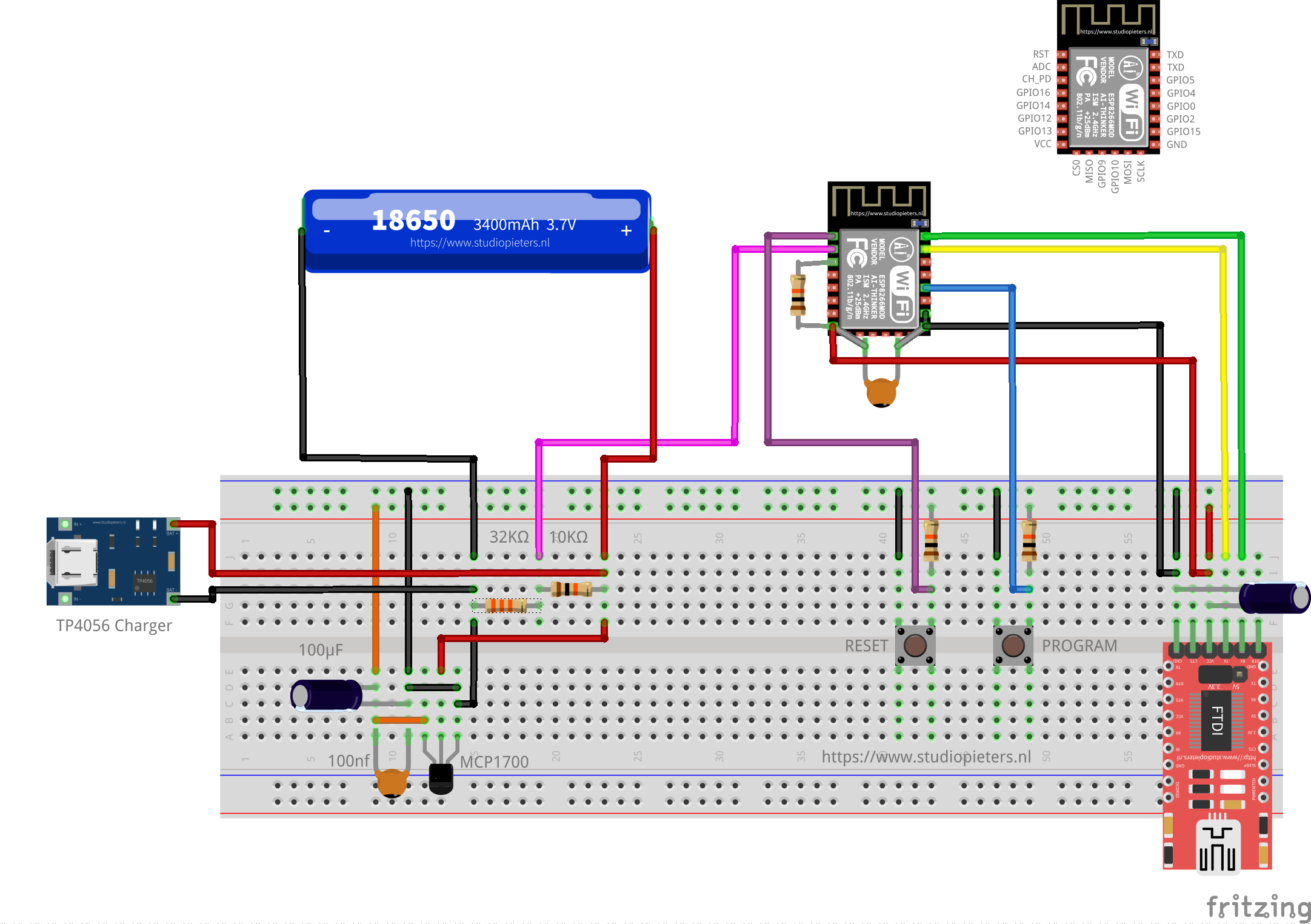

After you completed the circuit its time to move on to code. Code is written in C. the most important part is where the measurement takes place.
int low_battery_value;
float battery_value;

homekit_characteristic_t status_low_battery = HOMEKIT_CHARACTERISTIC_(STATUS_LOW_BATTERY, 0);

void battery_low_task(void *_args) {

        while (1) {
                battery_value = sdk_system_adc_read();
                printf ("ADC voltage is %.3f\n", 1.0 / 1024 * sdk_system_adc_read()* 4.2);
                vTaskDelay(3000 / portTICK_PERIOD_MS);
                if (1.0 / 1024 * battery_value * 4.2 < 3.900) {
                printf ("Battery value is low.\n");
                low_battery_value = 1;
                }
                else{
                printf ("Battery value is not low.\n");
                }
                homekit_characteristic_notify(&status_low_battery, HOMEKIT_UINT8(low_battery_value));
                vTaskDelay(3000 / portTICK_PERIOD_MS);
        }
}
void battery_low_init() {
        xTaskCreate(battery_low_task, "Battery Low", 256, NULL, 2, NULL);
}

&status_low_battery,


battery_low_init();
DOWNLOAD Eve for HomeKit
![]()
![]()
Status when the battery is not low in the HomeKit App.
status when the battery is not low in the EVE App.
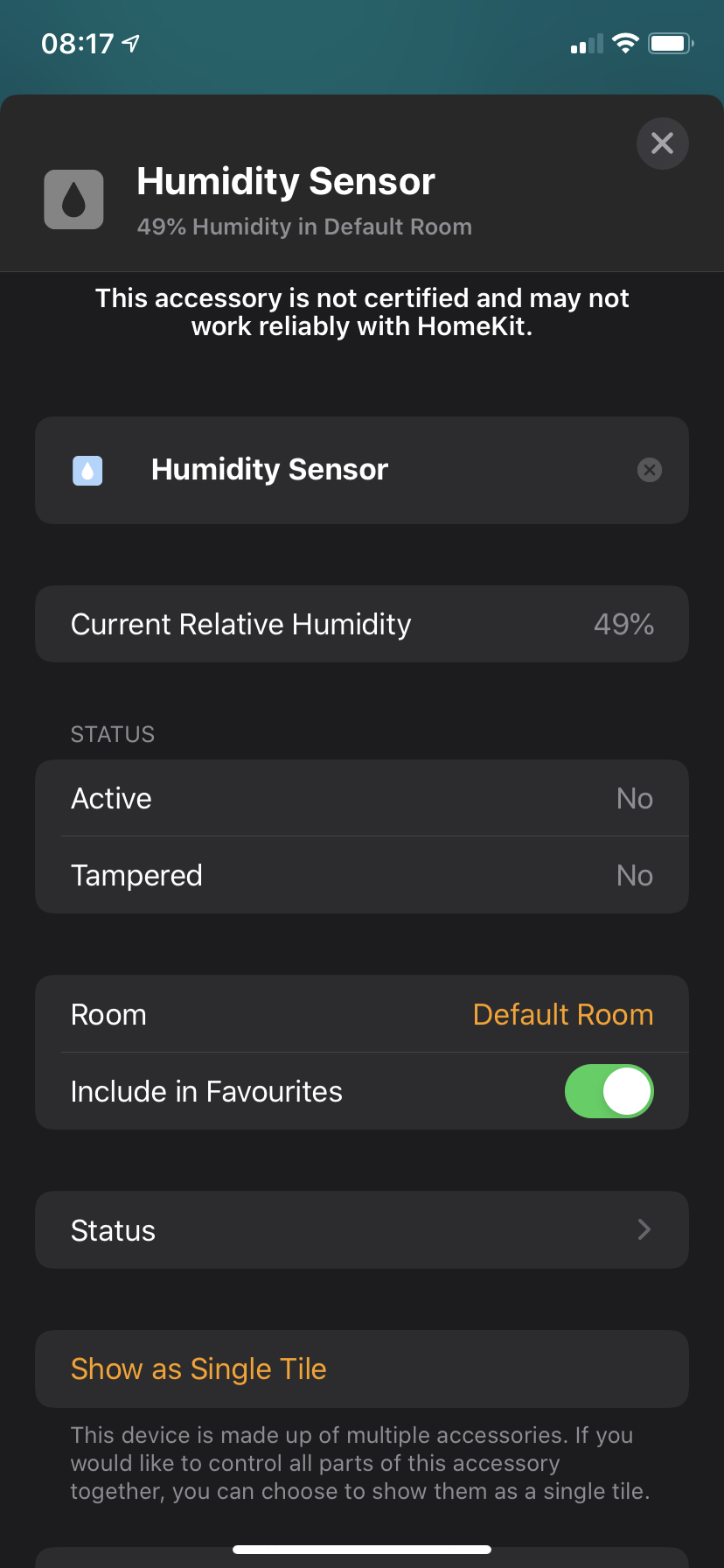
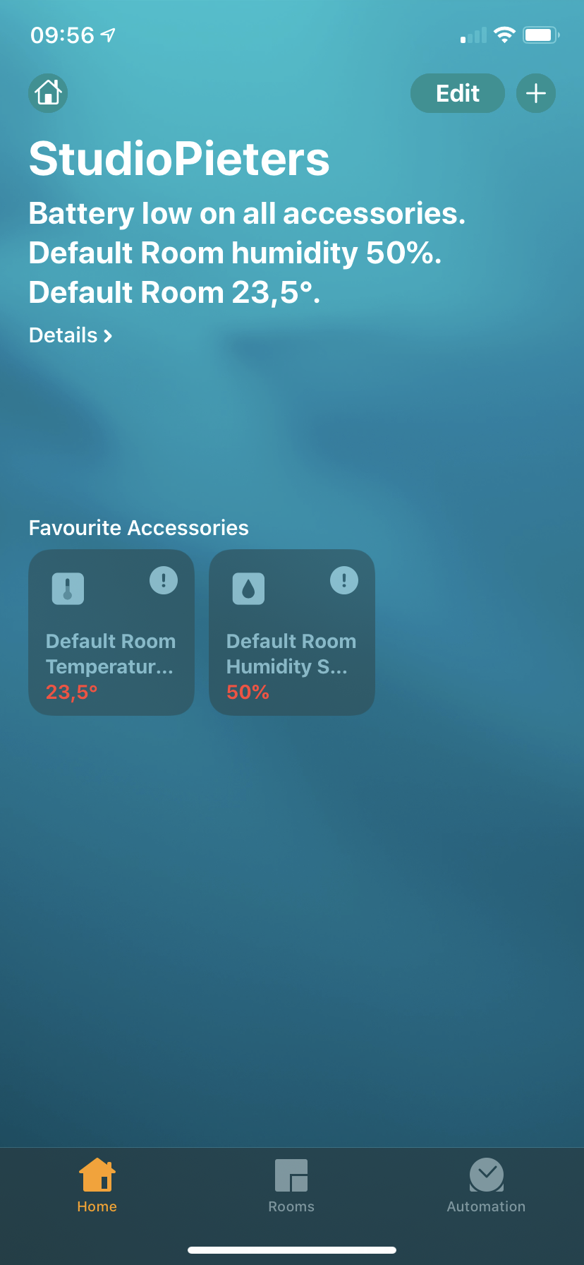
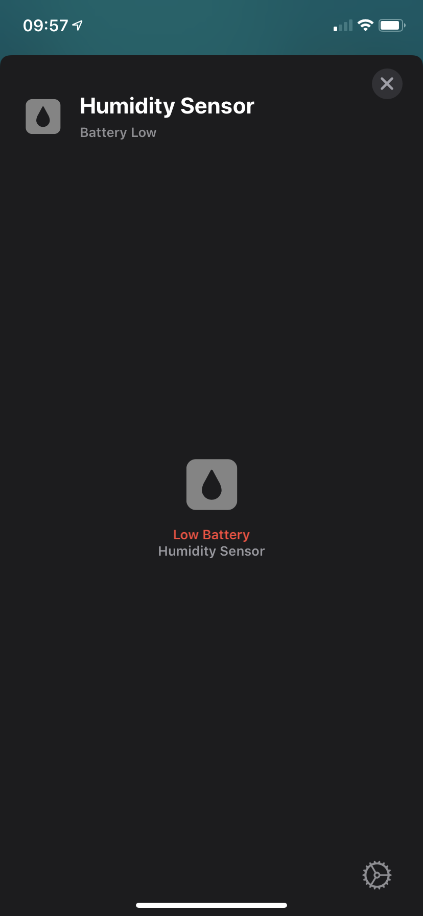
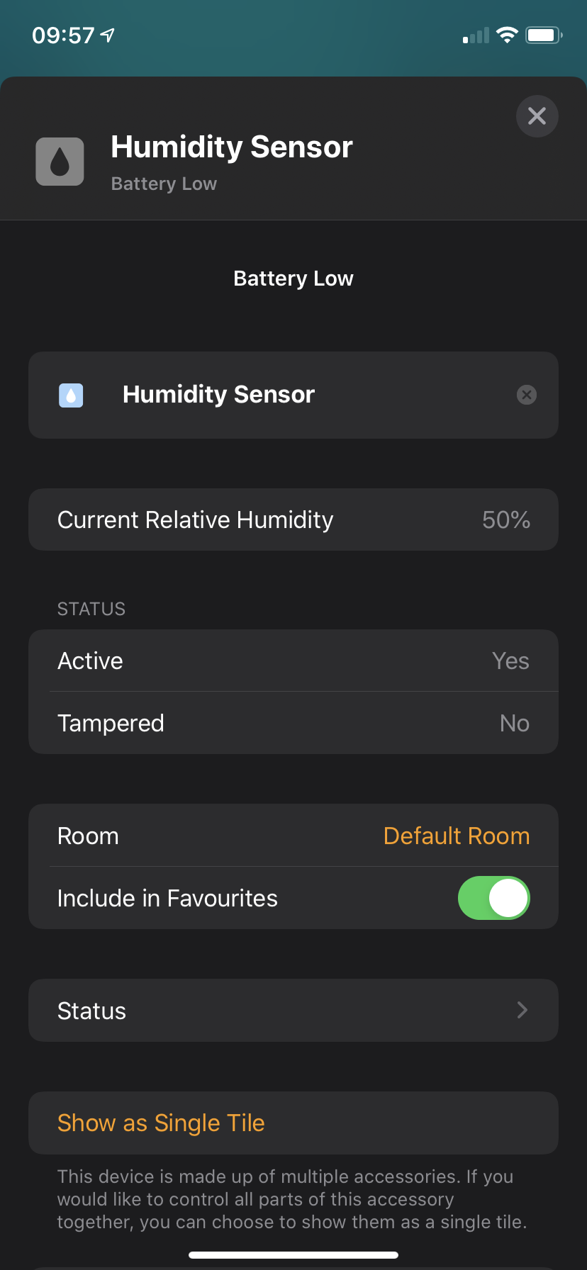
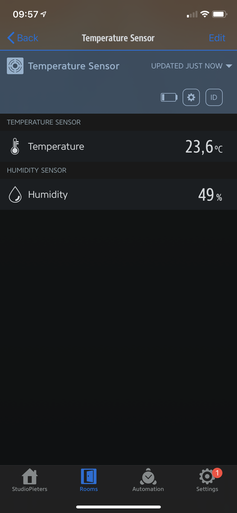
Status when the battery is low in the HomeKit App. The Measurements turn red. When we click on the sensor we see that it says Low Battery. Also in the settings of the sensor you will see Battery Low.
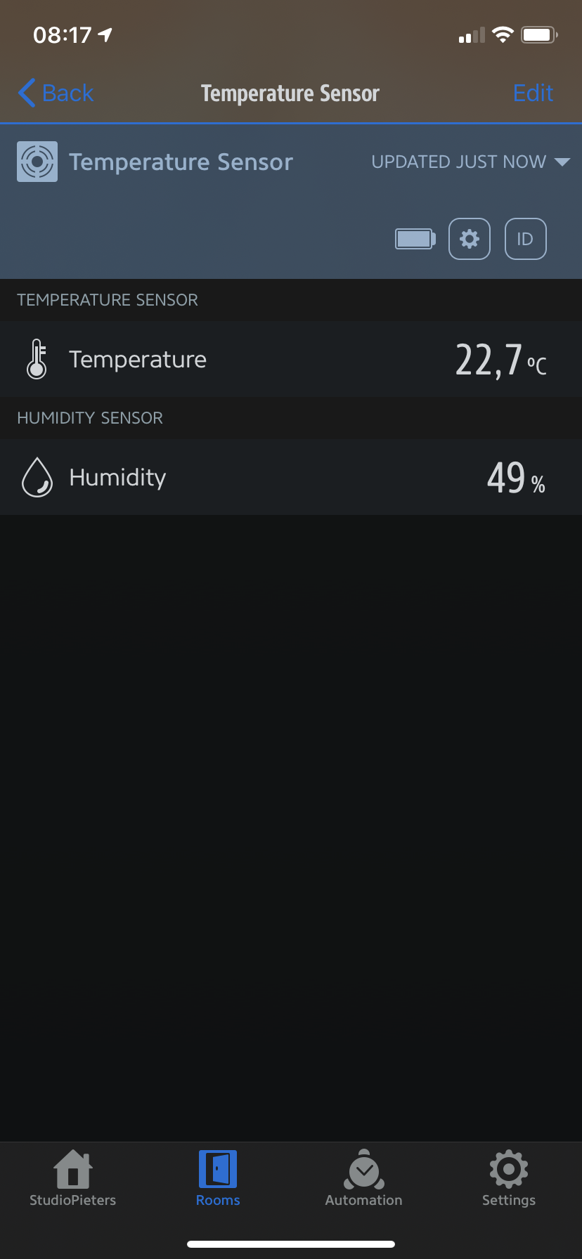
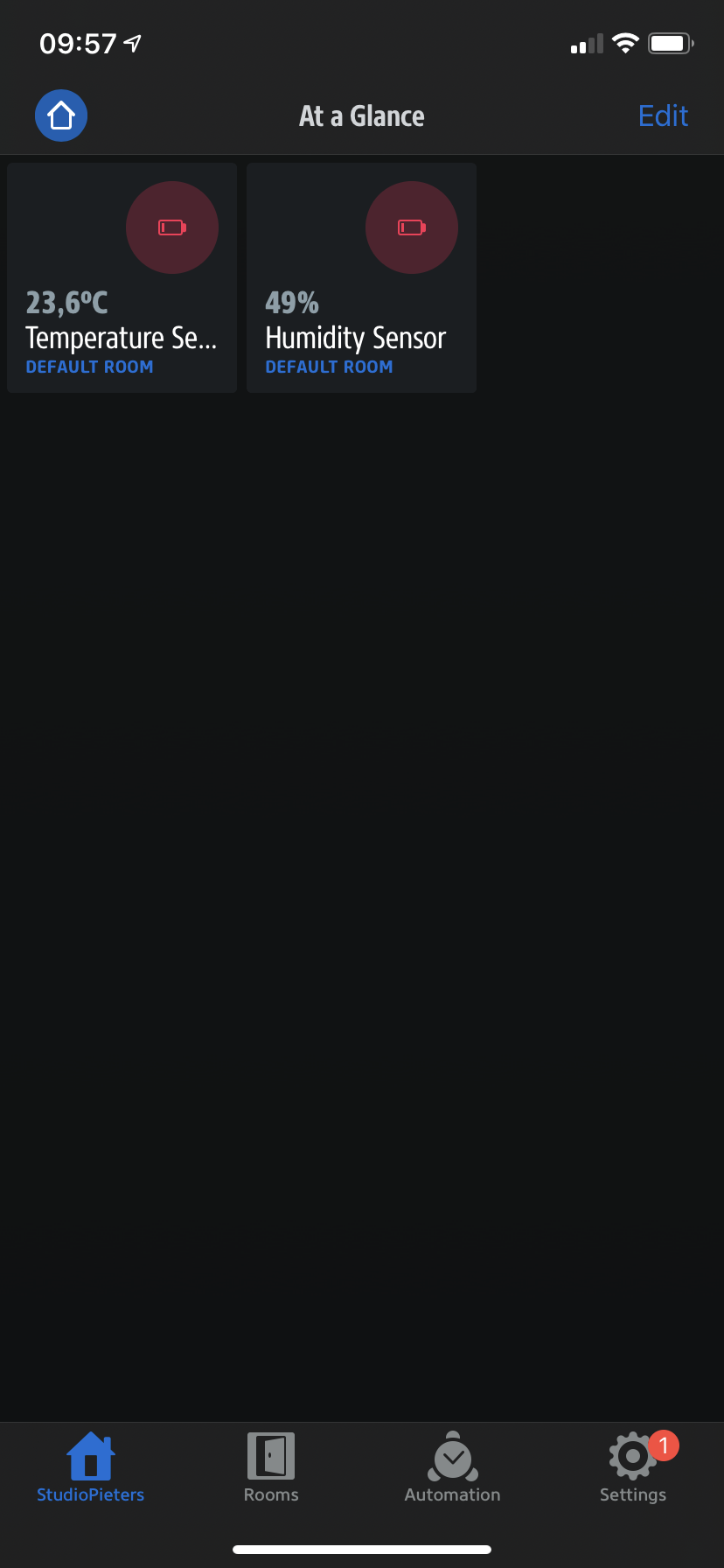
Status when the battery is low in the EVE App. You will see that there will appear a Low battery icon in the sensor tile. Also in the settings of the sensor you will see Battery Low icon.
![]()

DO YOU HAVE ANY QUESTIONS? LEAVE A COMMENT DOWN HERE.
Note: To produce and sell HomeKit compatible accessories, your company need to be certified for that (https://developer.apple.com/homekit/, If you’re interested in developing or manufacturing a HomeKit accessory that will be distributed or sold, your company must enroll in the MFi Program.) Espressif have their implementation of HomeKit framework, but it will give you it only if you have MFi certification (notice this text at the bottom of page you mentioned: Please note that the Espressif HomeKit SDK is available to MFi licensees only, and you need to provide the Account Number for verification purposes when requesting the SDK.).This project is a non-commercial implementation of HAP protocol, not meant for commercial use.
REFERENCE
Maxim Kulkin, esp-homekit-demo (2019), Demo of Apple HomeKit accessory server library , https://github.com/maximkulkin/esp-homekit-demo Paul Sokolovsky, esp-open-sdk (2019), Free and open (as much as possible) integrated SDK for ESP8266/ESP8285 chips, https://github.com/pfalcon/esp-open-sdk Espressif Systems, esptool (2019), ESP8266 and ESP32 serial bootloader utility, https://github.com/espressif/esptool HomeACcessoryKid, life-cycle-manager (2019), Initial install, WiFi settings and over the air firmware upgrades for any esp-open-rtos repository on GitHub, https://github.com/HomeACcessoryKid/life-cycle-manager evehome, eve app (2019), Eve works with all HomeKit-enabled accessories. See your home at a glance., https://www.evehome.com/en/eve-app Engineersgarage, nodemcu-battery-voltage-monitor (2020), https://www.engineersgarage.com/esp8266/nodemcu-battery-voltage-monitor