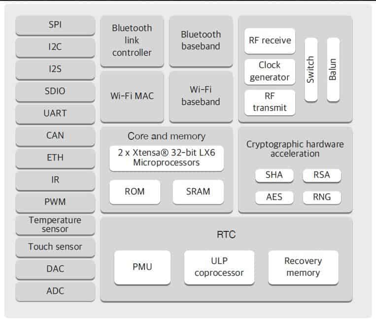
The ESP32 comes with 2 Xtensa 32-bit LX6 microprocessors. So, it is dual core. When we run code on the Arduino app, by default, it runs on core 1. In this blog we’ll show you how to run code on the ESP32 second core by creating tasks. You can run pieces of code simultaneously on both cores, and make your ESP32 multitasking!

ESP32 Dual Core with Arduino IDE
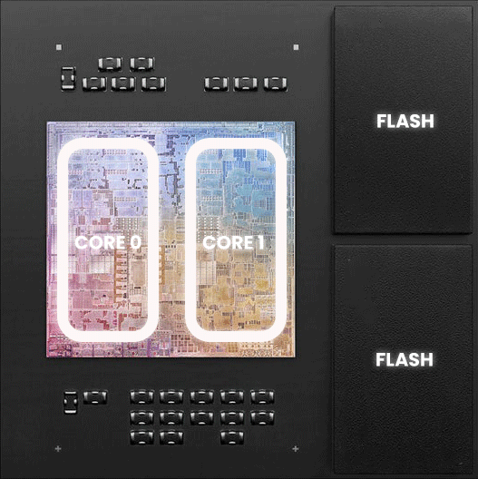
The ESP32 comes with 2 Xtensa 32-bit LX6 microprocessors, so it’s dual core, respectively: Core 0 and Core 1
When we upload code to the ESP32 using the Arduino IDE, it just runs – we don’t have to worry which core executes the code.
There’s a function that you can use to identify in which core the code is running:
xPortGetCoreID
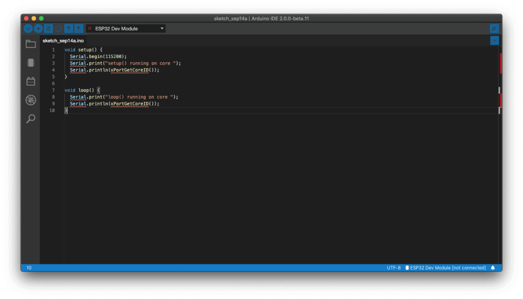
If you use that function in an Arduino sketch, you’ll see that both the setup() and loop() are running on core 1. Test it yourself by uploading the following sketch to your ESP32.
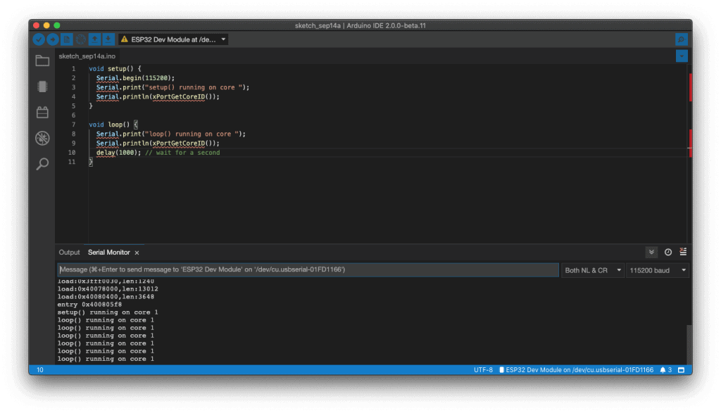
Open the Serial Monitor at a baud rate of 115200 and check the core the Arduino sketch is running on.

Create Tasks
The Arduino IDE supports FreeRTOS for the ESP32, which is a Real Time Operating system. This allows us to handle several tasks in parallel that run independently.
Tasks are pieces of code that execute something. For example, it can be blinking an LED, making a network request, measuring sensor readings, publishing sensor readings, etc…
To assign specific parts of code to a specific core, you need to create tasks. When creating a task you can chose in which core it will run, as well as its priority. Priority values start at 0, in which 0 is the lowest priority. The processor will run the tasks with higher priority first.
To create tasks you need to follow the next steps:
1. Create a task handle. An example for Task1:
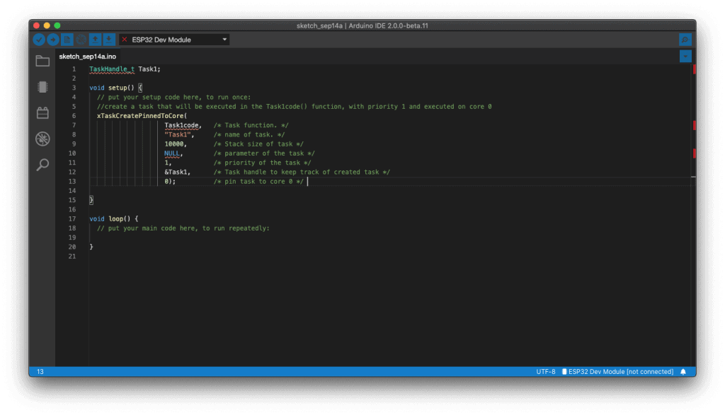
2. In the setup() create a a task assigned to a specific core using the xTaskCreatePinnedToCore function. That function takes several arguments, including the priority and the core where the task should run (the last parameter).
3. After creating the task, you should create a function that contains the code for the created task. In this example you need to create the Task1code() function. Here’s how the task function looks like:
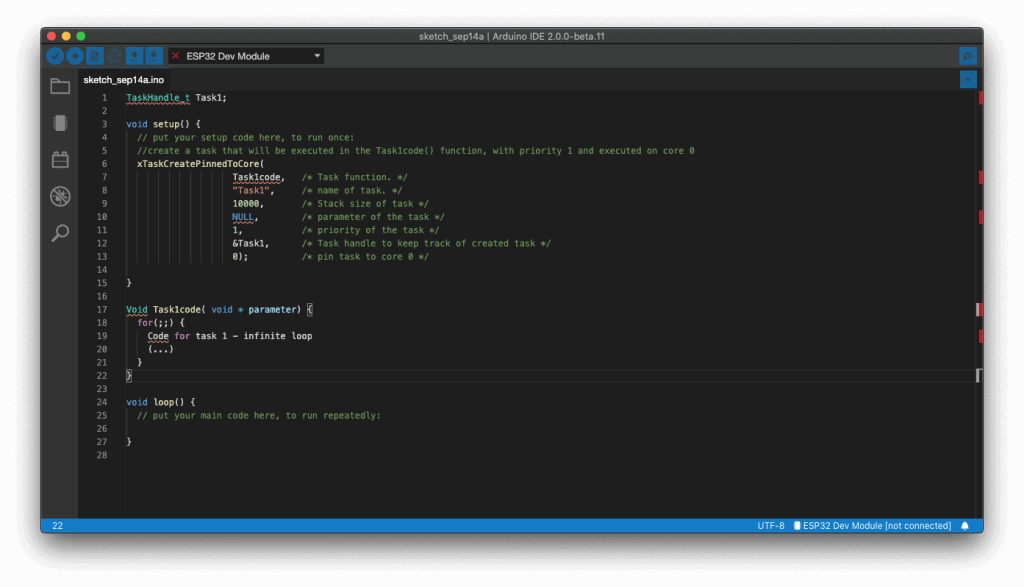
The for(;;) creates an infinite loop. So, this function runs similarly to the loop() function. You can use it as a second loop in your code, for example.
If during your code execution you want to delete the created task, you can use the vTaskDelete()function, that accepts the task handle (Task1) as argument:
vTaskDelete(Task1);

Let’s see how these concepts work with a simple example.
Create Tasks in Different Cores – Example
To follow this example, you need the following parts:
- ESP32 DOIT DEVKIT V1 Board
- 2x 5mm LED
- 2x 330 Ohm resistor
- Breadboard
- Jumper wires
You can use the preceding links or go directly to MakerAdvisor.com/tools to find all the parts for your projects at the best price!
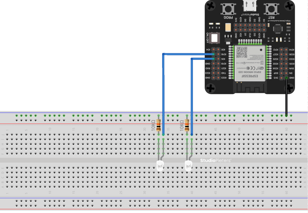
To create different tasks running on different cores we’ll create two tasks that blink LEDs with different delay times. Start by wiring two LEDs to the ESP32 as shown in the following diagram:
We’ll create two tasks running on different cores:
- Task1 runs on core 0;
- Task2 runs on core 1;
Upload the next sketch to your ESP32 to blink each LED in a different core:

How the Code Works
Note: in the code we create two tasks and assign one task to core 0 and another to core 1. Arduino sketches run on core 1 by default. So, you could write the code for Task2 in the loop() (there was no need to create another task). In this case we create two different tasks for learning purposes.
However, depending on your project requirements, it may be more practical to organize your code in tasks as demonstrated in this example.
The code starts by creating a task handle for Task 1 and Task 2 called Task1 and Task2.
TaskHandle_t Task1;
TaskHandle_t Task2;
Assign GPIO 2 and GPIO 4 to the LEDs:
const int led1 = 2;
const int led2 = 4;
In the setup(), initialize the Serial Monitor at a baud rate of 115200:
Serial.begin(115200);Declare the LEDs as outputs:
pinMode(led1, OUTPUT);
pinMode(led2, OUTPUT);
Then, create Task1 using the xTaskCreatePinnedToCore() function:
xTaskCreatePinnedToCore(
             Task1code, /* Task function. */
             "Task1",   /* name of task. */
             10000,     /* Stack size of task */
             NULL,      /* parameter of the task */
             1,         /* priority of the task */
             &Task1,    /* Task handle to keep track of created task */
             0);        /* pin task to core 0 */
Task1 will be implemented with the Task1code() function. So, we need to create that function later on the code. We give the task priority 1, and pinned it to core 0.
We create Task2 using the same method:
xTaskCreatePinnedToCore(
             Task2code,  /* Task function. */
             "Task2",    /* name of task. */
             10000,      /* Stack size of task */
             NULL,       /* parameter of the task */
             1,          /* priority of the task */
             &Task2,     /* Task handle to keep track of created task */
             1);         /* pin task to core 0 */
After creating the tasks, we need to create the functions that will execute those tasks.
void Task1code( void * pvParameters ){
  Serial.print("Task1 running on core ");
  Serial.println(xPortGetCoreID());

  for(;;){
    digitalWrite(led1, HIGH);
    delay(1000);
    digitalWrite(led1, LOW);
    delay(1000);
  }
}
The function to Task1 is called Task1code() (you can call it whatever you want). For debugging purposes, we first print the core in which the task is running:
Serial.print("Task1 running on core ");
Serial.println(xPortGetCoreID());
Then, we have an infinite loop similar to the loop() on the Arduino sketch. In that loop, we blink LED1 every one second.
The same thing happens for Task2, but we blink the LED with a different delay time.
void Task2code( void * pvParameters ){
  Serial.print("Task2 running on core ");
  Serial.println(xPortGetCoreID());

  for(;;){
    digitalWrite(led2, HIGH);
    delay(700);
    digitalWrite(led2, LOW);
    delay(700);
  }
}
Finally, the loop() function is empty:
void loop() { }Note: as mentioned previously, the Arduino loop() runs on core 1. So, instead of creating a task to run on core 1, you can simply write your code inside the loop().
Demonstration
Upload the code to your ESP32. Make sure you have the right board and COM port selected.
Open the Serial Monitor at a baud rate of 115200. You should get the following messages:
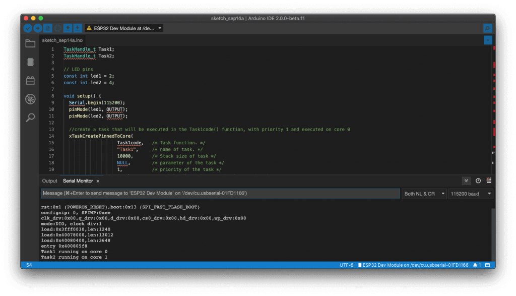
As expected Task1 is running on core 0, while Task2 is running on core 1.

In your circuit, one LED should be blinking every 1 second, and the other should be blinking every 700 milliseconds.
Wrapping Up
In summary:
- The ESP32 is dual core;
- Arduino sketches run on core 1 by default;
- To use core 0 you need to create tasks;
- You can use the xTaskCreatePinnedToCore() function to pin a specific task to a specific core;
- Using this method you can run two different tasks independently and simultaneously using the two cores.
In this tutorial we’ve provided a simple example with LEDs. The idea is to use this method with more advanced projects with real world applications. For example, it may be useful to use one core to take sensor readings and other to publish those readings on a home automation system.
Reference:
Espressif, ESP32 Datasheet, https://www.espressif.com/sites/default/files/documentation/esp32_datasheet_en.pdf Randomnerdtutorials, How to use ESP32 Dual Core with Arduino IDE, https://randomnerdtutorials.com/esp32-dual-core-arduino-ide