After releasing my project the ESP32 – Homekit Camera, some readers reported issues when trying to use the ESP32-CAM. This blog is a compilation with the most common errors when using the ESP32-CAM and how to fix them.
Some of our readers reported errors when trying to follow the ESP32 – Homekit Camera Project. There are some modified lines in the code, so most of the problems related with this project should be fixed. Please note that we couldn’t reproduce some of the errors on our end. However, we’ve gathered all the information given by our readers to get answers to the most common issues.

Under construction
The ESP32 HomeKit camera is still a work in progress (at time of writing), It’s works, but there still has to be done some work.
Common errors
A fatal error occurred: Failed to connect to ESP32: Timed out waiting for packet header
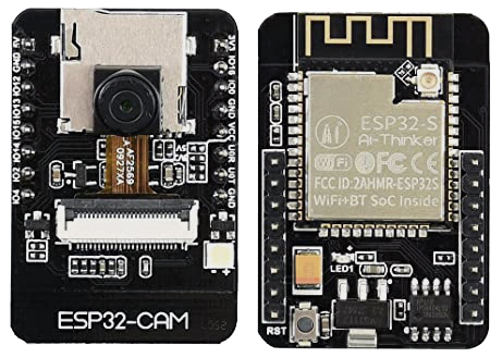
This error means that the ESP32-CAM is not in flashing mode or it is not connected properly to the FTDI programmer. Double-check that you’ve followed the exact steps to put your ESP32-CAM in flashing mode. Failing to complete one of the steps may result in that error. Here are the steps you need to follow. Connect the ESP32-CAM board to your computer using an FTDI programmer.
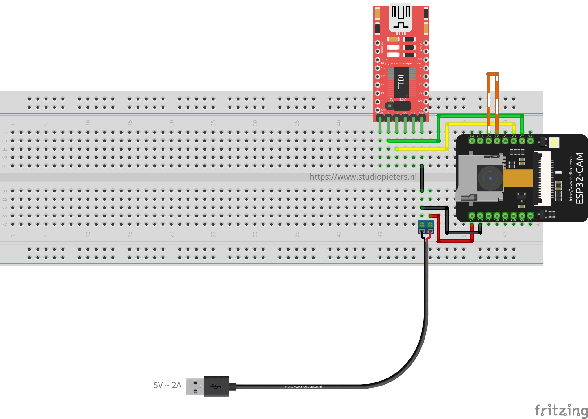
Many FTDI programmers have a Jumper that allows you to select 3.3V or 5V. Make sure the jumper is in the right place to select 5V.
Note: I advise not to use the FTDI Programmer as power source but use a external one shown in the scheme above.
Important: GPIO 0 needs to be connected to GND so that you’re able to upload code.
| ESP32-CAM | FTDI Programmer |
| GND | GND |
| 5V | VCC (5V) |
| U0R | TX |
| U0T | RX |
| GPIO 0 | GND |
FTDI Programmer output
Measure the output voltage of your FTDI programmer (VCC and GND) using a Multimeter to ensure it’s providing 5V to your ESP32-CAM.
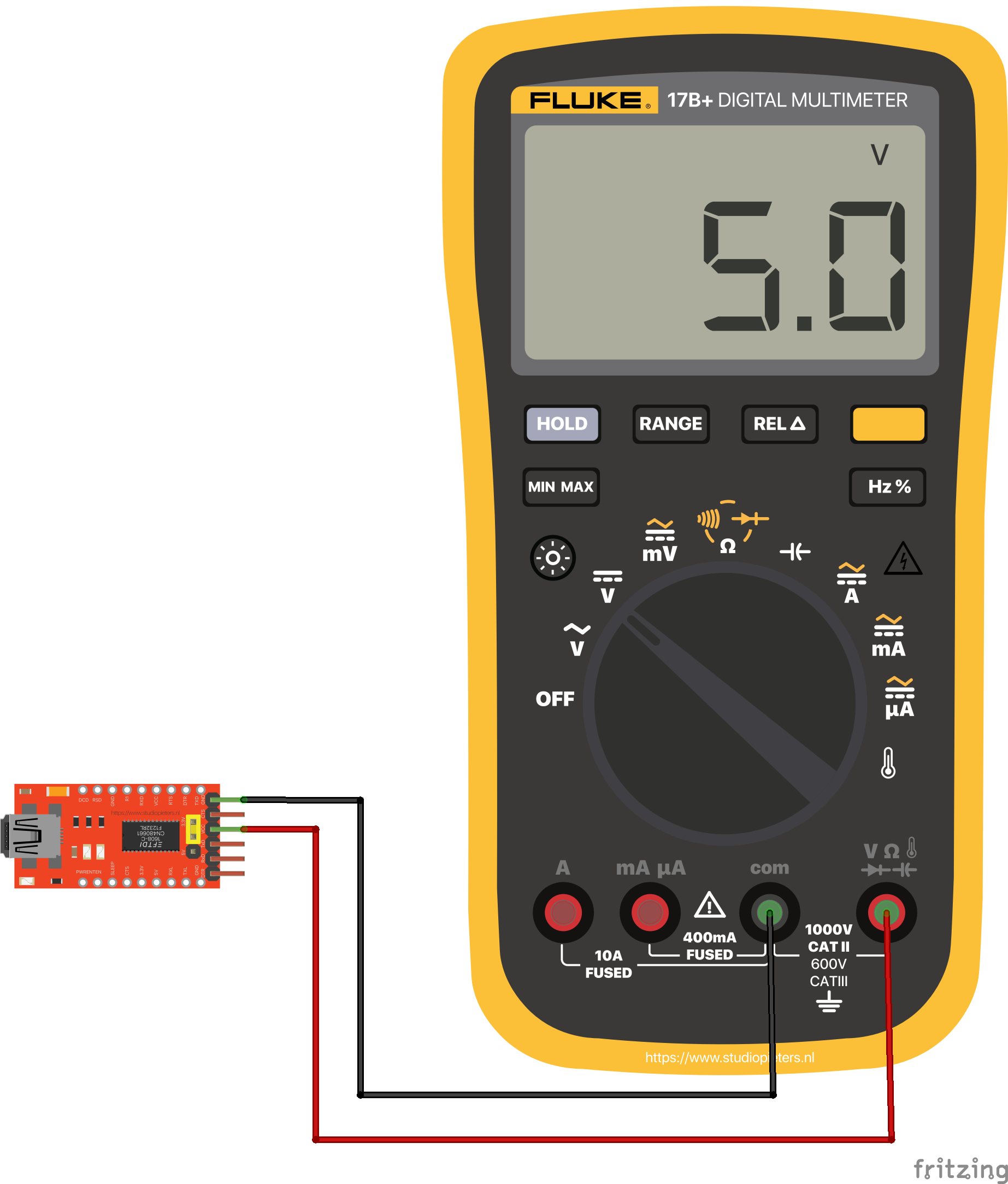
Note: I advise not to use the FTDI Programmer as power source but use a external one this give more stable results.
Camera init failed
E (12013) esp32_camera: Camera init failed with error 0x20001
If you get this exact error, it means that your camera OVX is not connected properly to your ESP32 board or you have the wrong pin assignment in the code. Sometimes, unplugging and plugging the FTDI programmer multiple times or restart the board multiple times, might solve the issue.
Camera not connected properly
The camera has a tiny connector and you must ensure it’s connected in the the right away and with a secure fit, otherwise it will fail to establish a connection.

Wrong pin assignment in the code
When you get this error, it might also mean that you didn’t select the right board in the define section or the pin definition is wrong for your board. Make sure you select the right camera module in your projects.
There are many esp32-cam boards being released (“fake boards”) that the wiring between the ESP32 and the OV camera might be different, so selecting the camera module, might not be enough. You might need to check each gpio declaration with your board pinout. For example, M5Stack board without PSRAM has a different pin assignment than the M5STACK with PSRAM.
Not enough power through USB source
If you’re powering your ESP32 through a USB port on your computer, it might not be supplying enough power.
Note: I advise not to use the FTDI Programmer as power source but use a external one this give more stable results.
The camera/connector is broken
If you get this error, it might also mean that your camera or the camera ribbon is broken. If that is the case, you may get a new OV2640 camera module.
Brownout detector or Guru meditation error
Brownout detector was triggered
It means that there’s some sort of hardware problem. It’s often related to one of the following issues:
- Poor quality USB cable
- USB cable is too long;
- Board with some defect (bad solder joints);
- Bad computer USB port;
- Not enough power provided by the computer USB port.
Solution: try a different shorter USB cable (with data wires) use a different computer USB port or use a USB hub with an external power supply some readers reported that when powering the ESP32-CAM with 5V, the issue was fixed.
Weak Wi-Fi Signal
Some readers reported that after powering the ESP32-CAM with 5V, they’ve gotten a more stable Wi-Fi signal. The ESP32-CAM has the option to use either the built-in antenna or an external antenna. If your ESP32-CAM AI-Thinker has no Wi-Fi connection or poor connection, it might have the external antenna enabled. If you connect an external antenna to the connector, it should work fine.

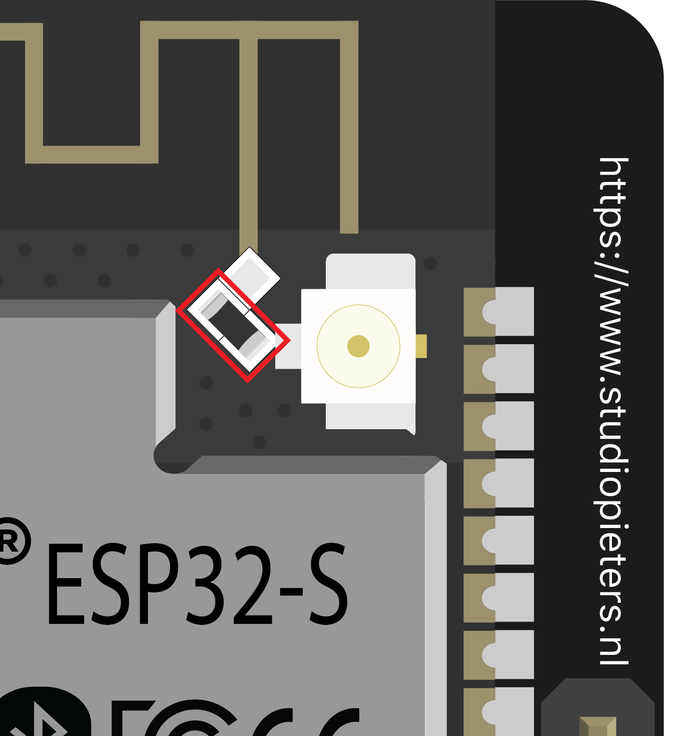
Check if the jumper 0K resistor by the antenna connector is in the proper position for the desired antenna. There are 3 little white squares laid out like a “<” with the middle position being common. The following photo shows a closer look at that area. You can clearly see a small 0K resistor connecting to the built-in antenna. With board turned so the the PCB antenna is up:
To use the PCB antenna, the resistor must be on the top position, like this: /
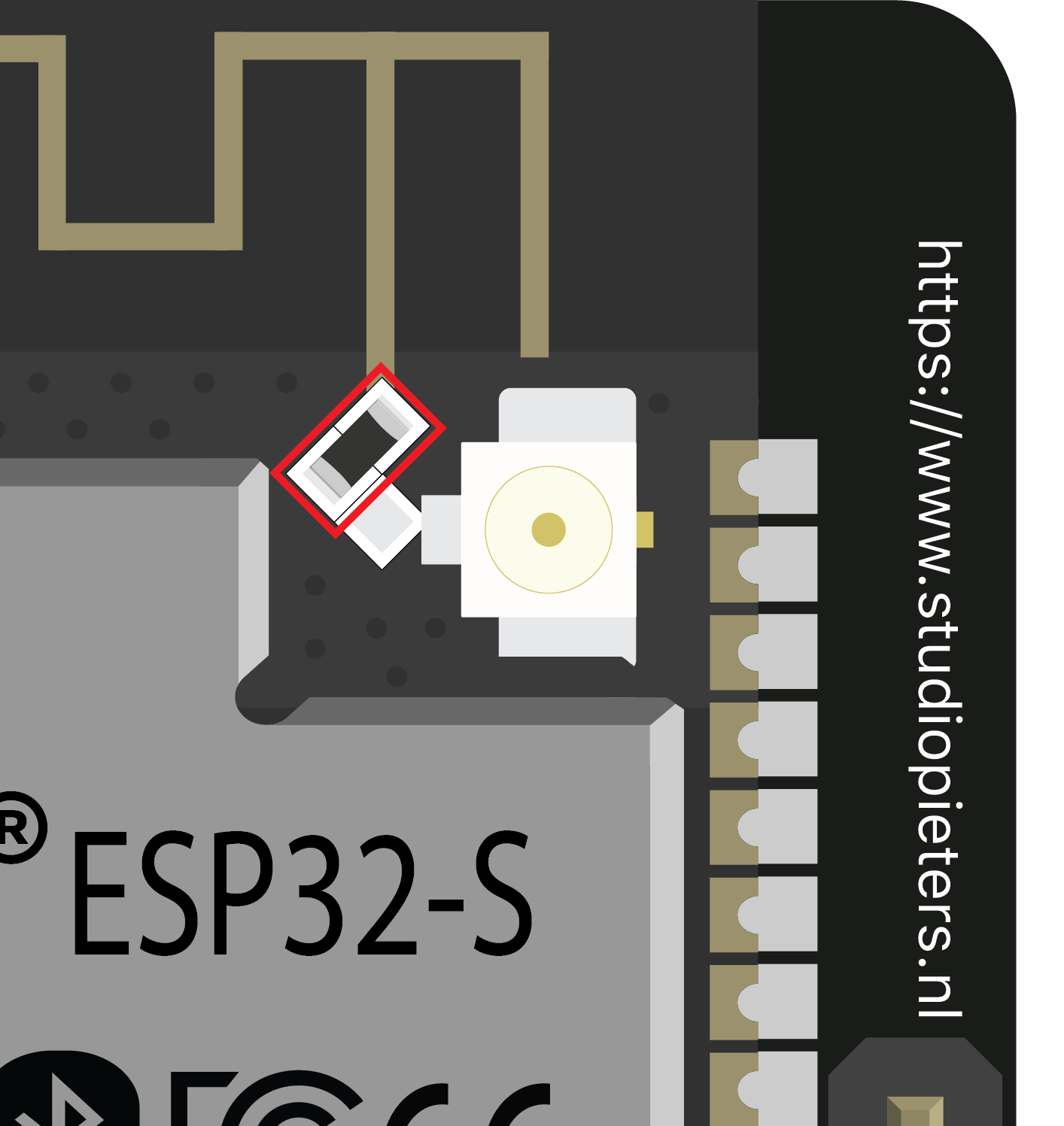
For the antenna connector, the resistor must be on the bottom position, like this: \
The image lags/shows lots of latency
Having some latency is normal for such a small and cheap camera. Some readers have suggested the following to reduce latency: Power the ESP32-CAM with a standalone 5V power supply Reduce the frame size with the following in your code.
Using larger microSD card sizes
According to he datasheet, the ESP32-CAM should only supports 4GB microSD cards. However, we’ve tested with 16GB microSD card and it works well. You might not be able to store more than 4GB, even though you have 16GB. We haven’t tested storing more than 4GB, so we’re not sure about this.
We hope you’ve found this troubleshooting guide useful and you were able to make your ESP32-CAM work with your projects. It is very difficult to understand what’s wrong with your project when we can’t reproduce the error on our end. However, if you post the error, there might be other readers with the same issue/solution, so we encourage you to interact in the comment’s section.

If you have any other issues or suggestions on how to fix them, please post a comment below.