This blog will step you through the process of taking a finished model, generating a tool path and exporting it as g-code. Making the output compatible with GRBL controllers as in my CNC machine, the CNC 3018.

Fusion 360 | For personal or hobby use
First, we need AutoCAD Fusion 360. Autodesk Fusion 360 is awesome, it’s one of my favorite pieces of software. Get access to Fusion 360 for personal use, including standard features for home-based, non-commercial projects. Fusion 360 for personal use is a limited free version that includes basic functionality and can be renewed on a 3-year basis.

Let’s Start
Open the file you want milled (you can download the example I am using here) and switch to the ‘CAM’ workspace. This switches us over to Fusion’s computer aided manufacturing functionality for generating CNC tool paths.

Open AutoCAD Fusion 360.
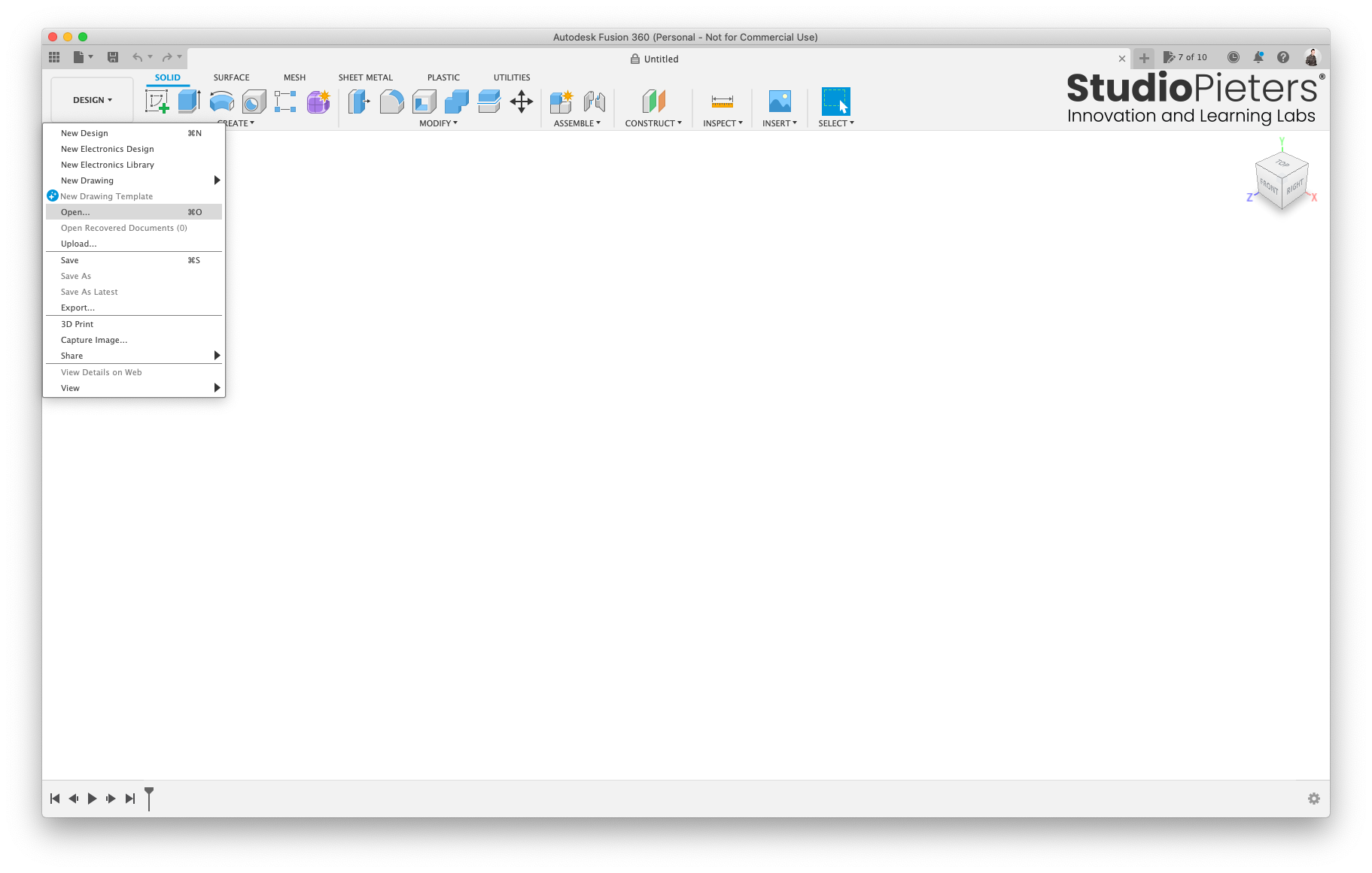
Click File icon and select Open…
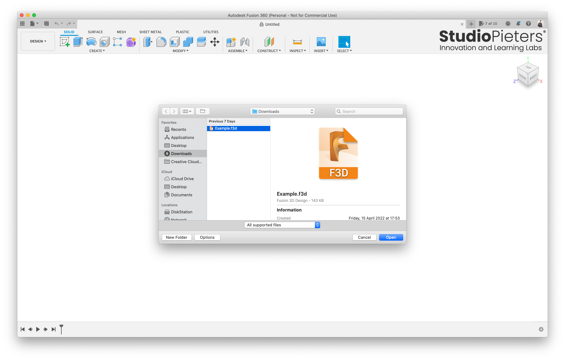
Go to the Download folder and open the Example.f3d file.
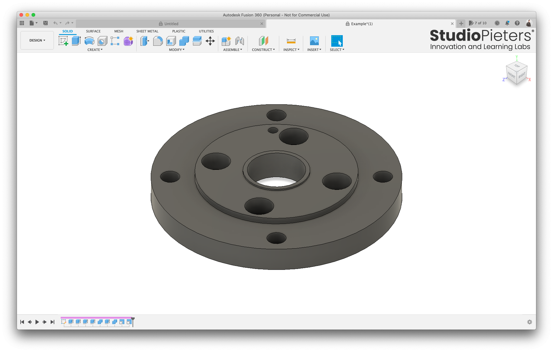
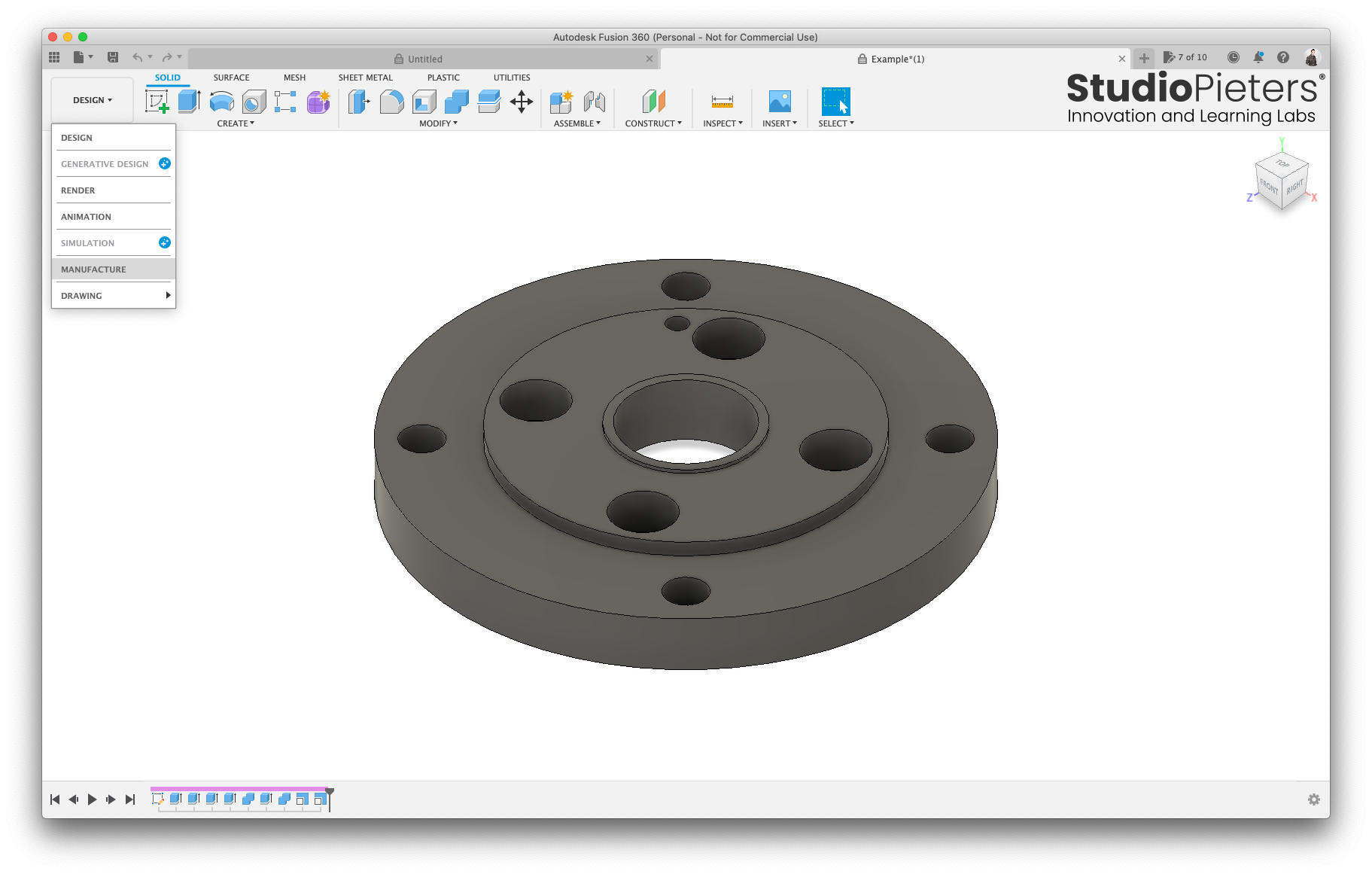
You should now see this.
Go to DESIGN and select MANUFACTURE.
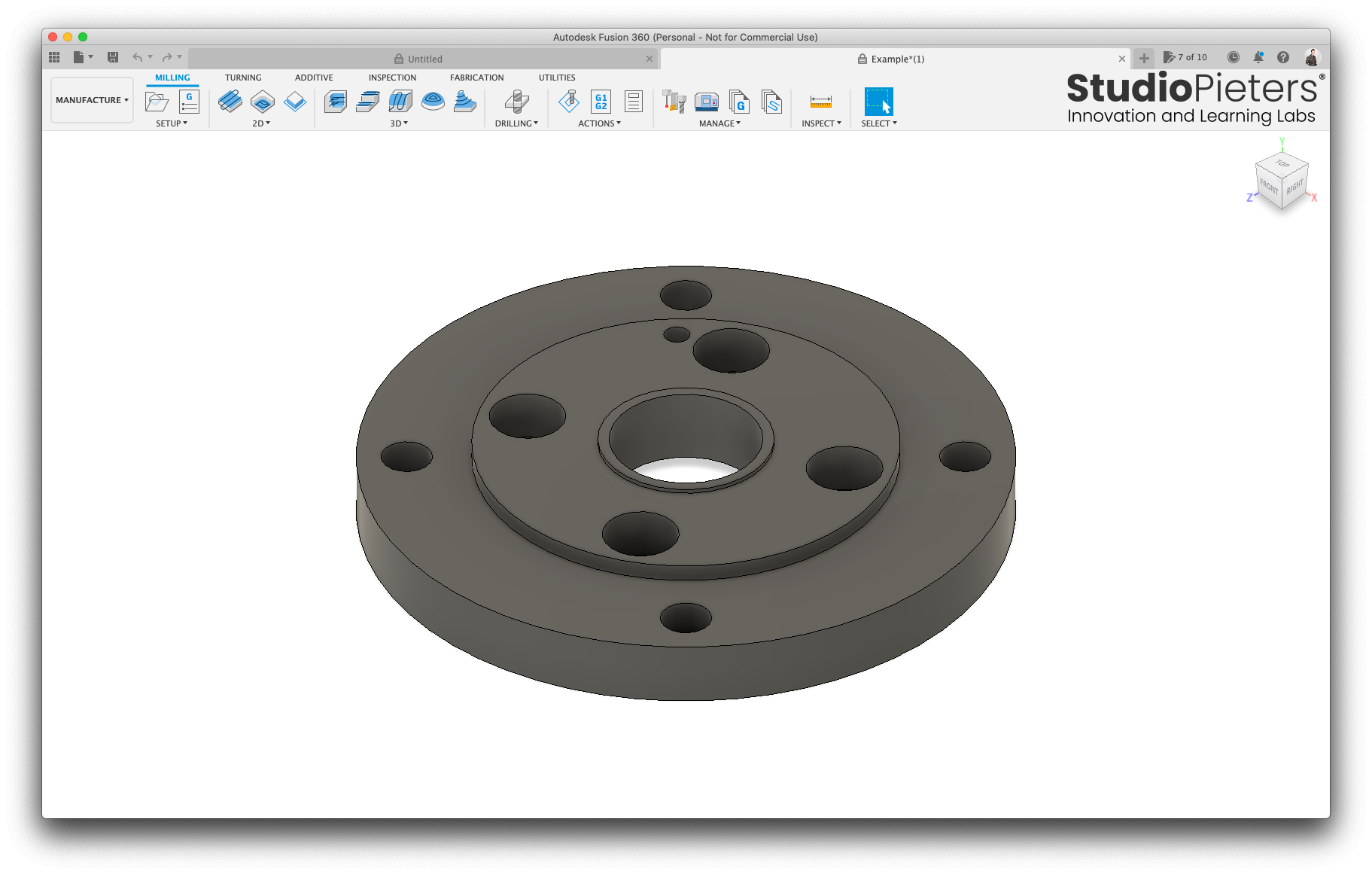
You are now in the Manufacture or CAM environment of AutoCAD Fusion 360.
SETUP
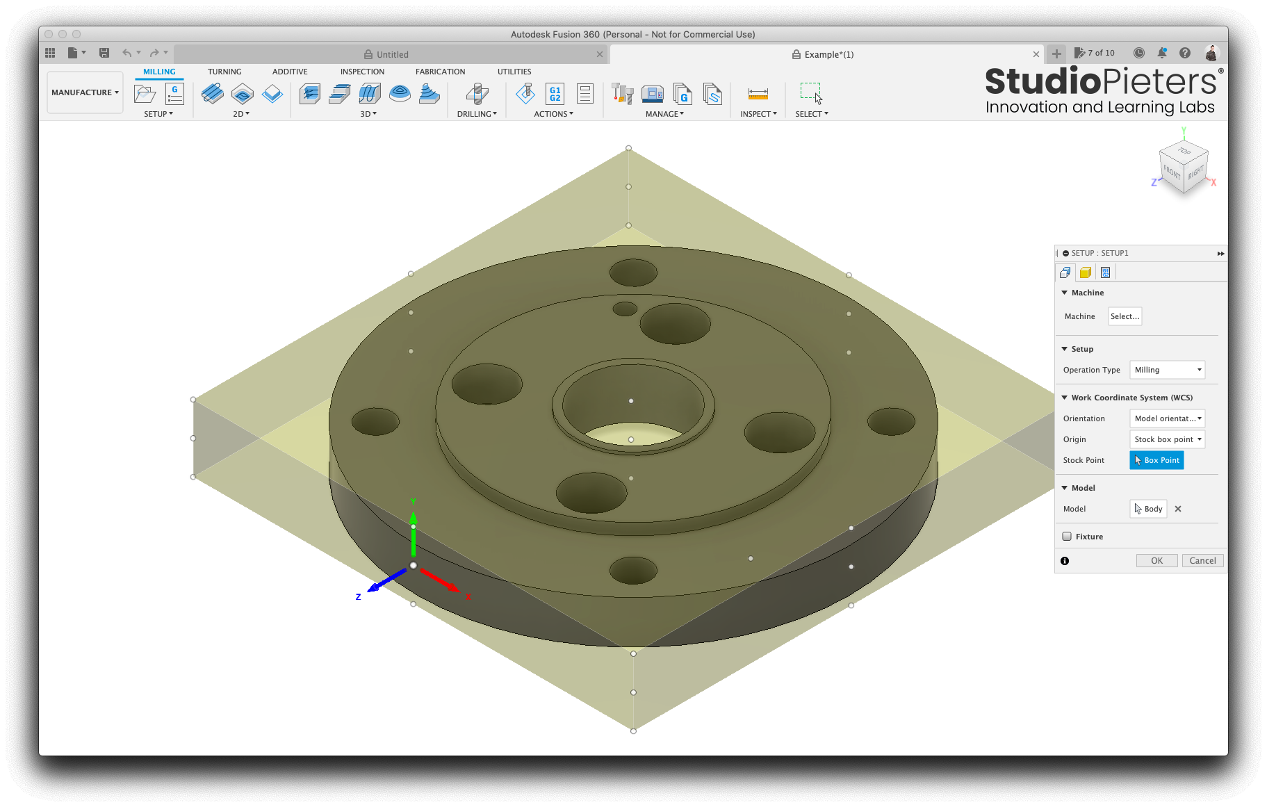
A setup holds general properties about the milling job. It lets us tell Fusion a few details about the stock, or the material we will be using to cut the part from. Most importantly, it lets us set up how our stock will be orientated in our mill. We need to set the coordinate system such that the Z-axis points up, while the x and y-axis from the plane matching the top of the stock (the yellow semi-transparent box).

Select the SETUP menu and select New Setup.
You now should see the SETUP menu.
In the Setup tab, select the orientation drop down and click Select Z axis/plane & X axis.
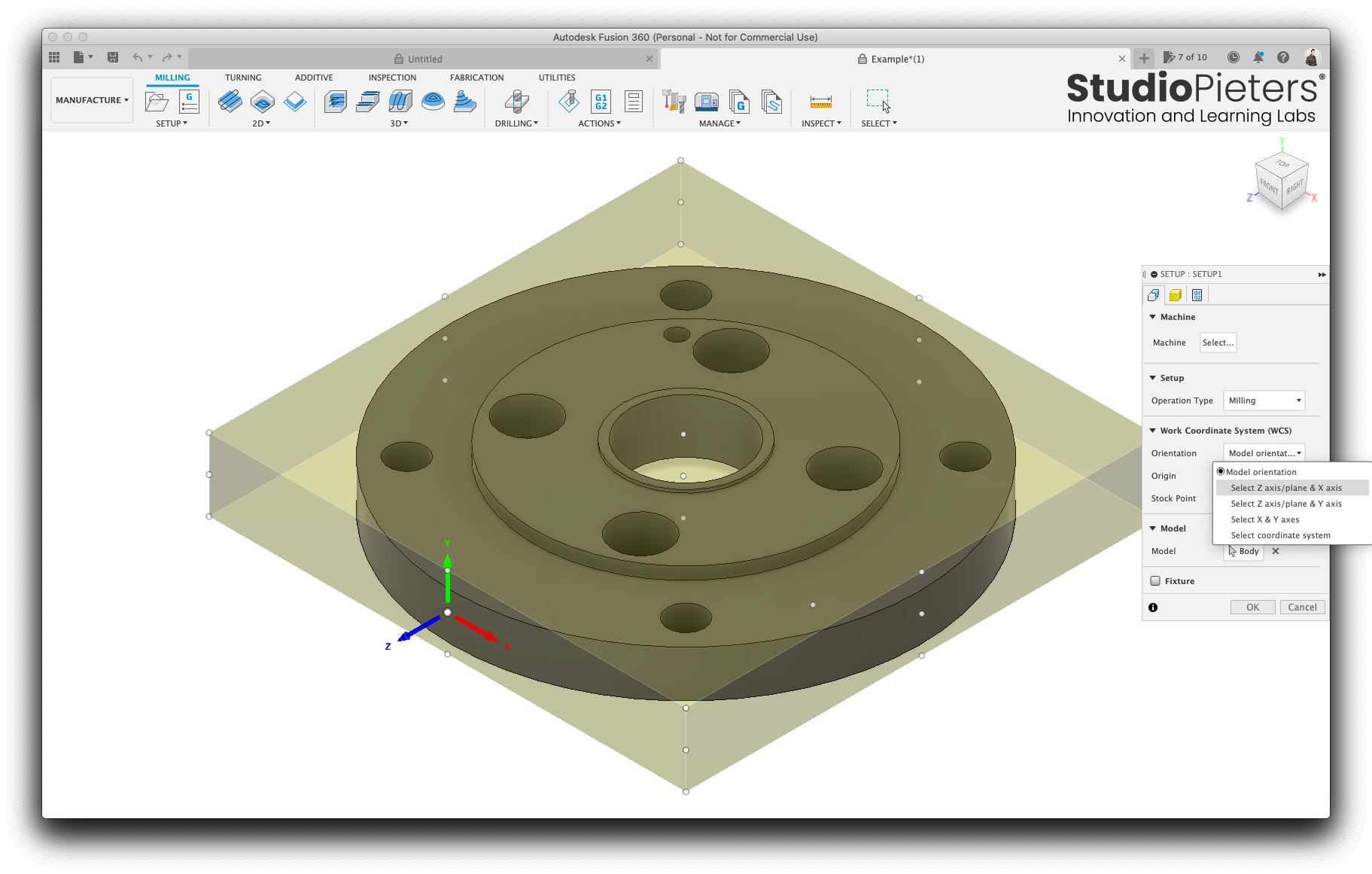
Select the button with the arrow behind A-Axis.
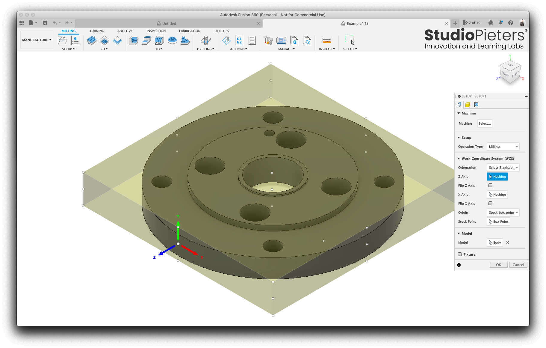
We need to define the Z-Axis, we do so by clicking on the side of the model (the white marked in the picture).
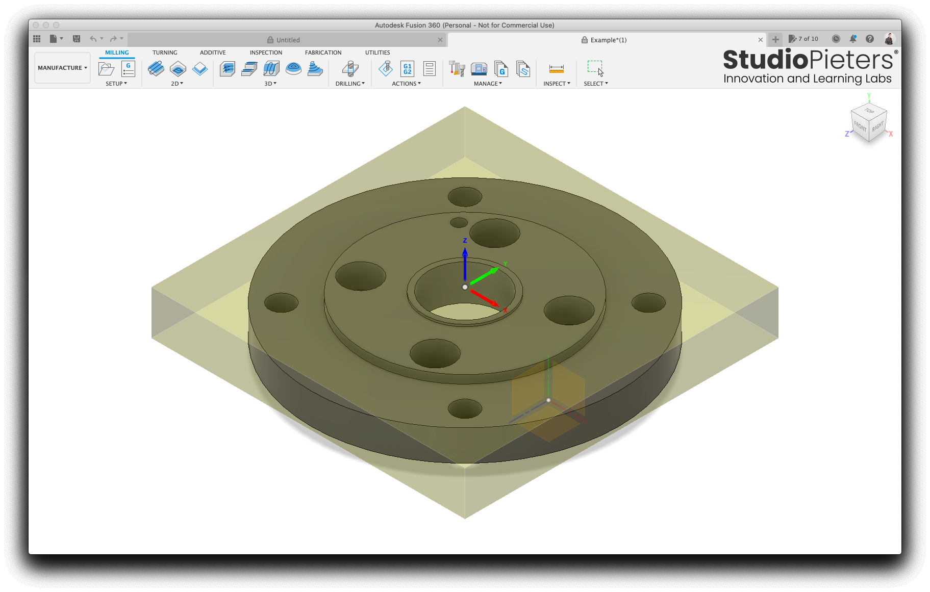
As you can see in the picture below, the Z-Axis is now pointing up.
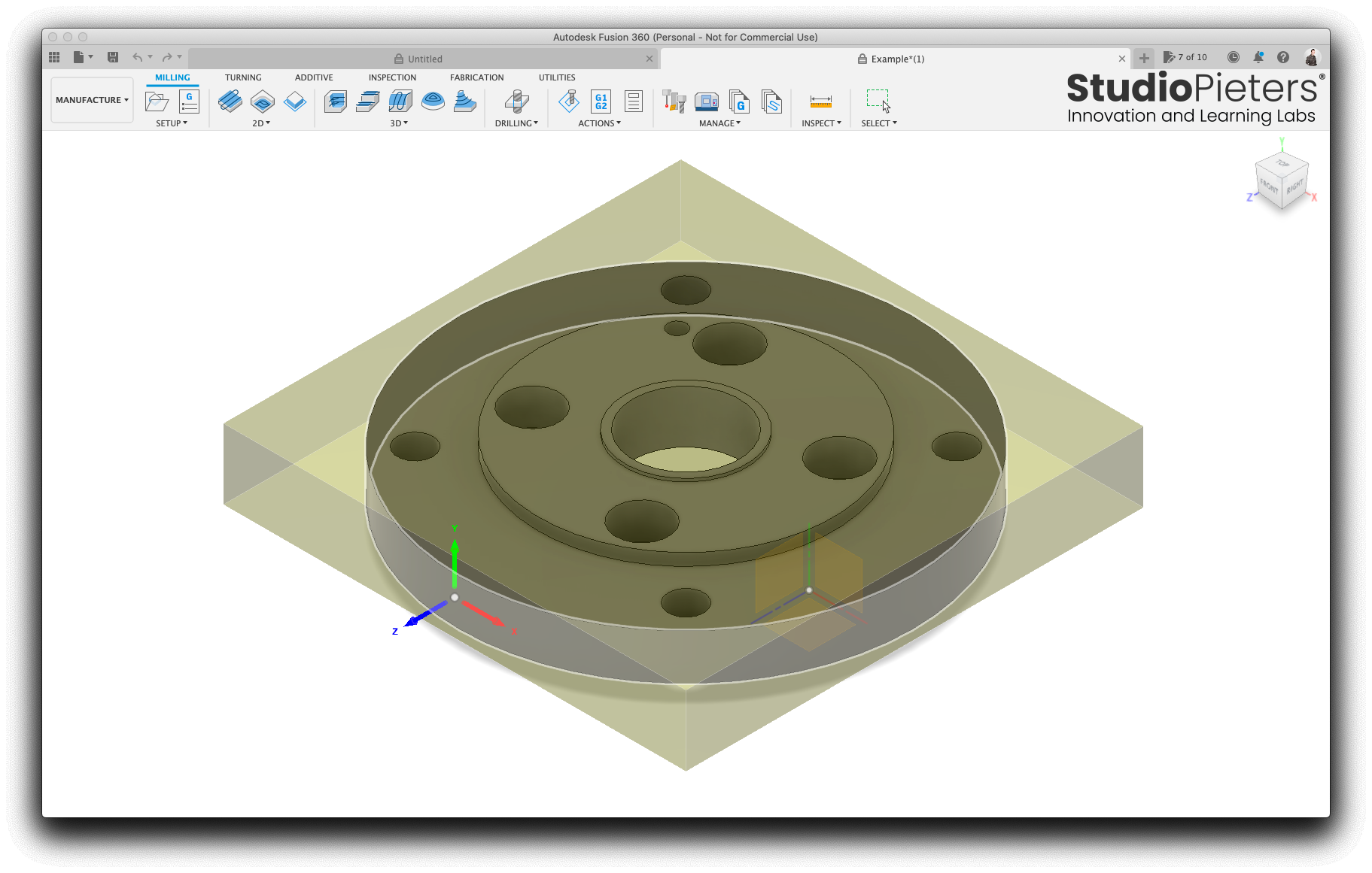
Select Box Point to select a stock point to be the origin for our job.

Click the left upper point on the top of the yellow semi-transparent stock box.
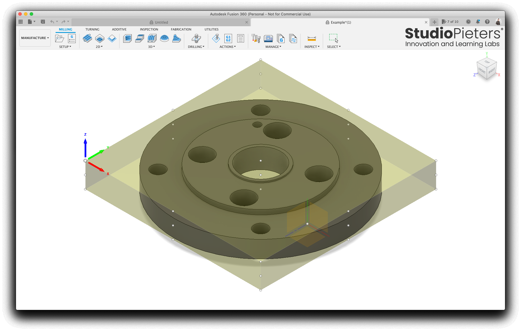
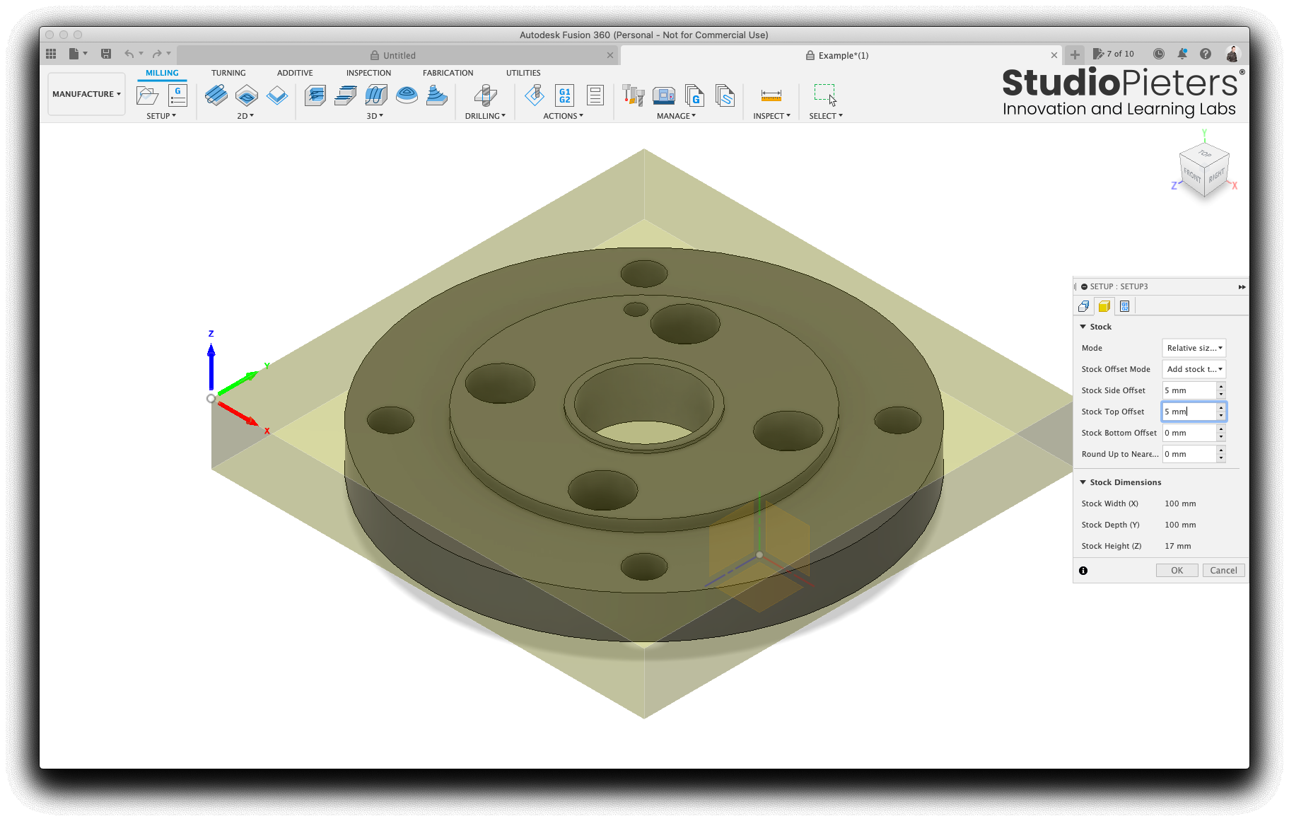
Select the Stock tab.

Bump the side offset up by to 5 mm, to give us a bit of a margin when cutting the part. Set the top offset to 0 mm (assuming we will be cutting this from material that is the same thickness as the part) and press, OK.
Pocket Clearing
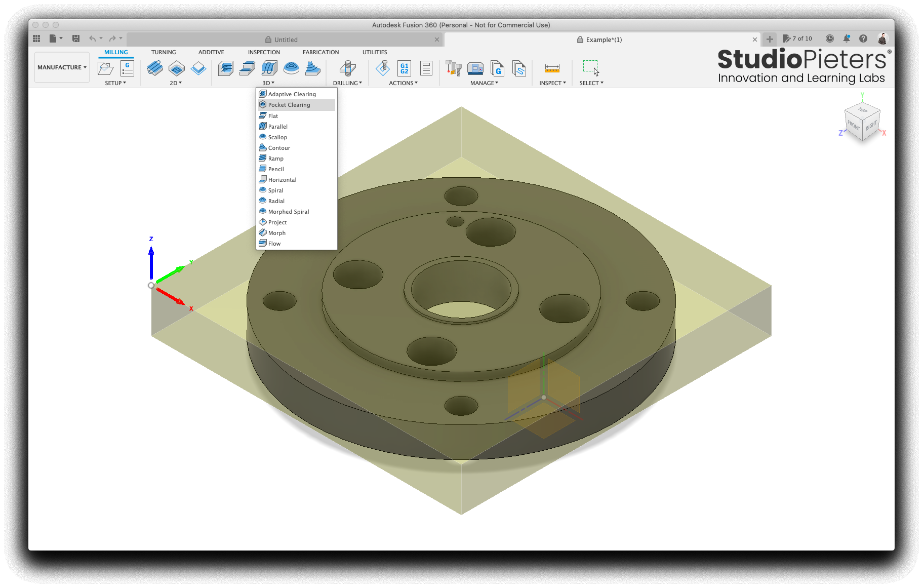
Now we are ready to start giving actions for our CNC mill to perform. The first is to clear out all the holes in the piece, some of these are countersunk, so we will use ‘pocket clearing’ for this.

Select the 3D menu and press Pocket Clearing.
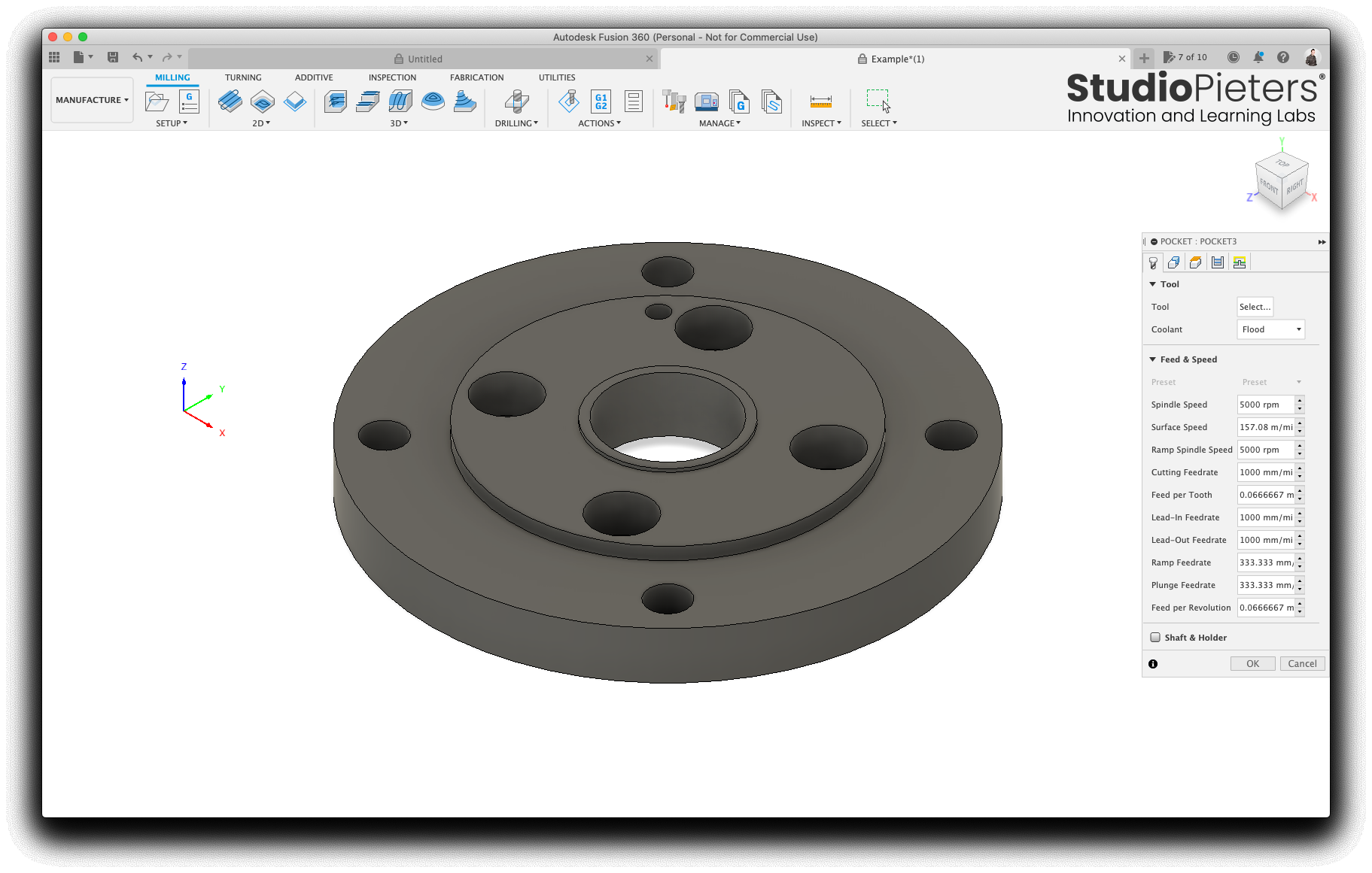
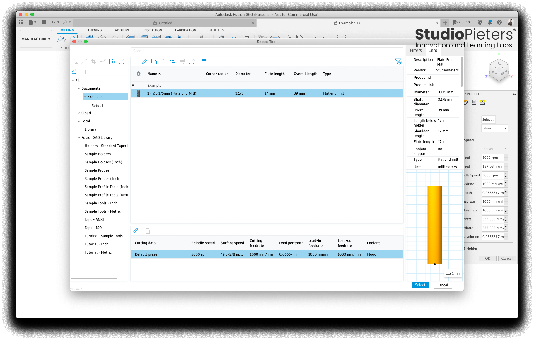
Press the Select… button next to tool.
A new window opens, press the blue plus sign.
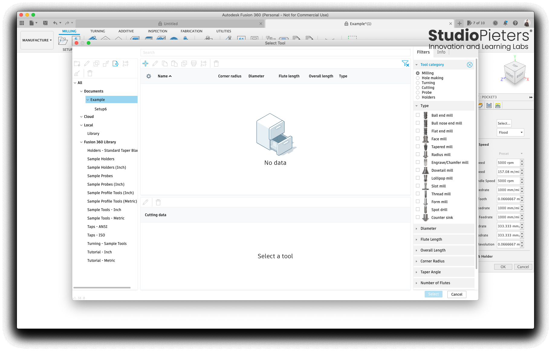
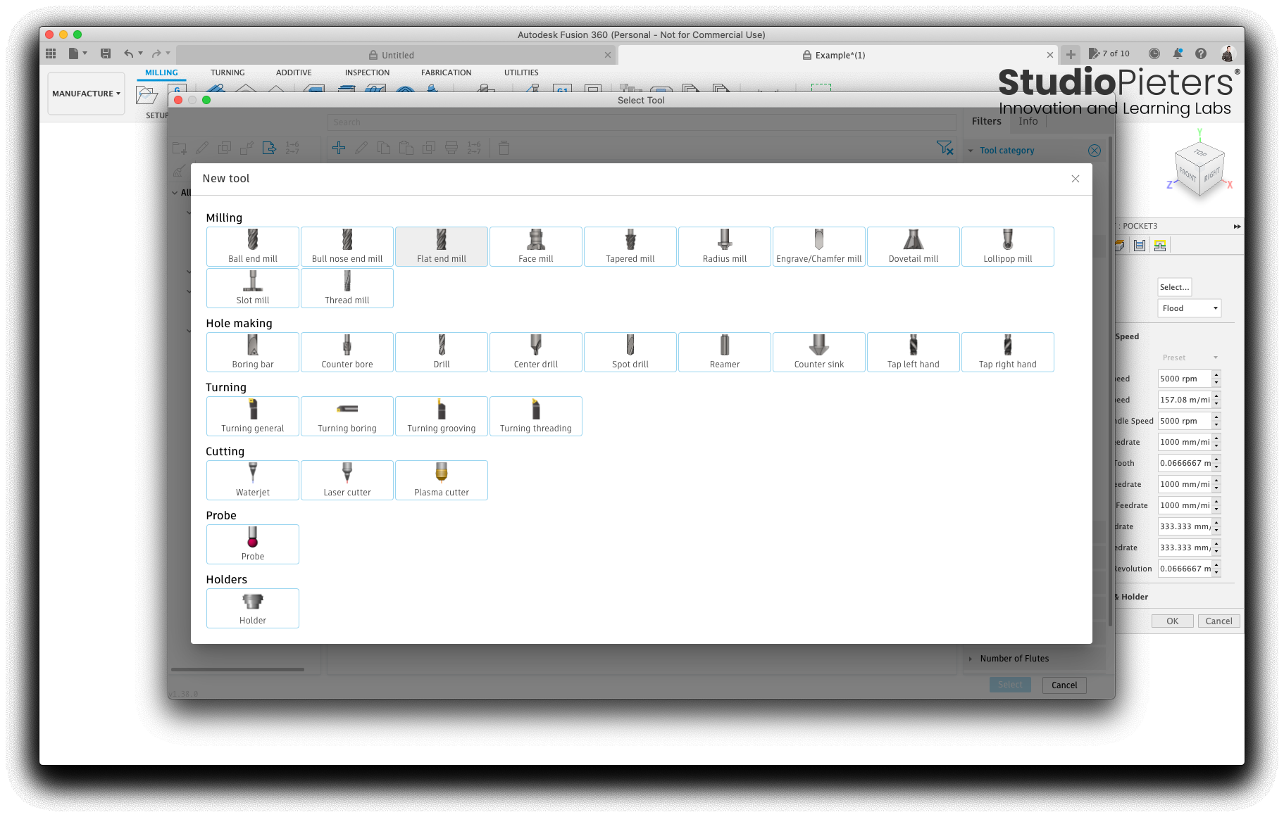
Once again, a new window opens called New tool.
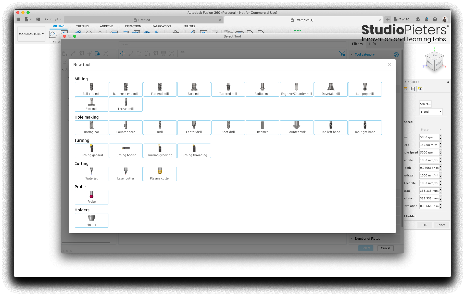
Here we select a Flat End Mill.
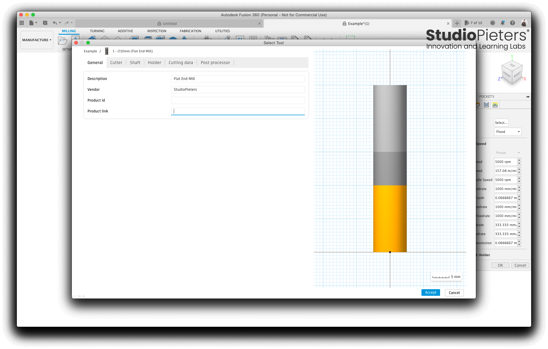
Now we can set up our Mill. In the General tab, you can fill in whatever you want.
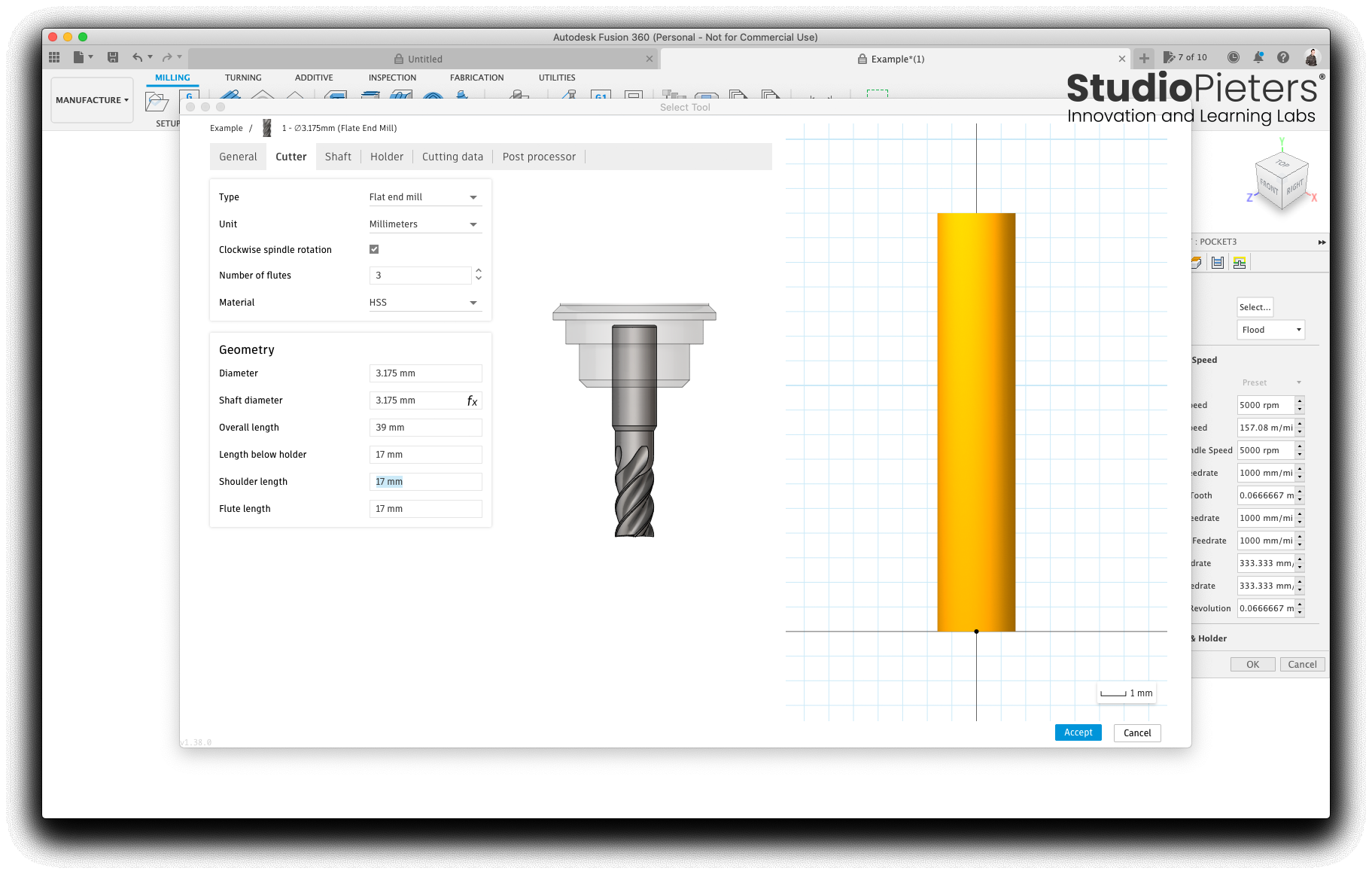
Select the cutter tab and fill out all the details for the milling bit you are going to use. I used a set of digital calipers to make all the measurements. The only that might not be obvious is ‘Number of flutes’, a flute is the channel in the side of the bit. Those helical troughs that spiral up the side. My tool had two. Press Accept when finished entering the details.
Now that we have Set up our drilling tool, we press Select.
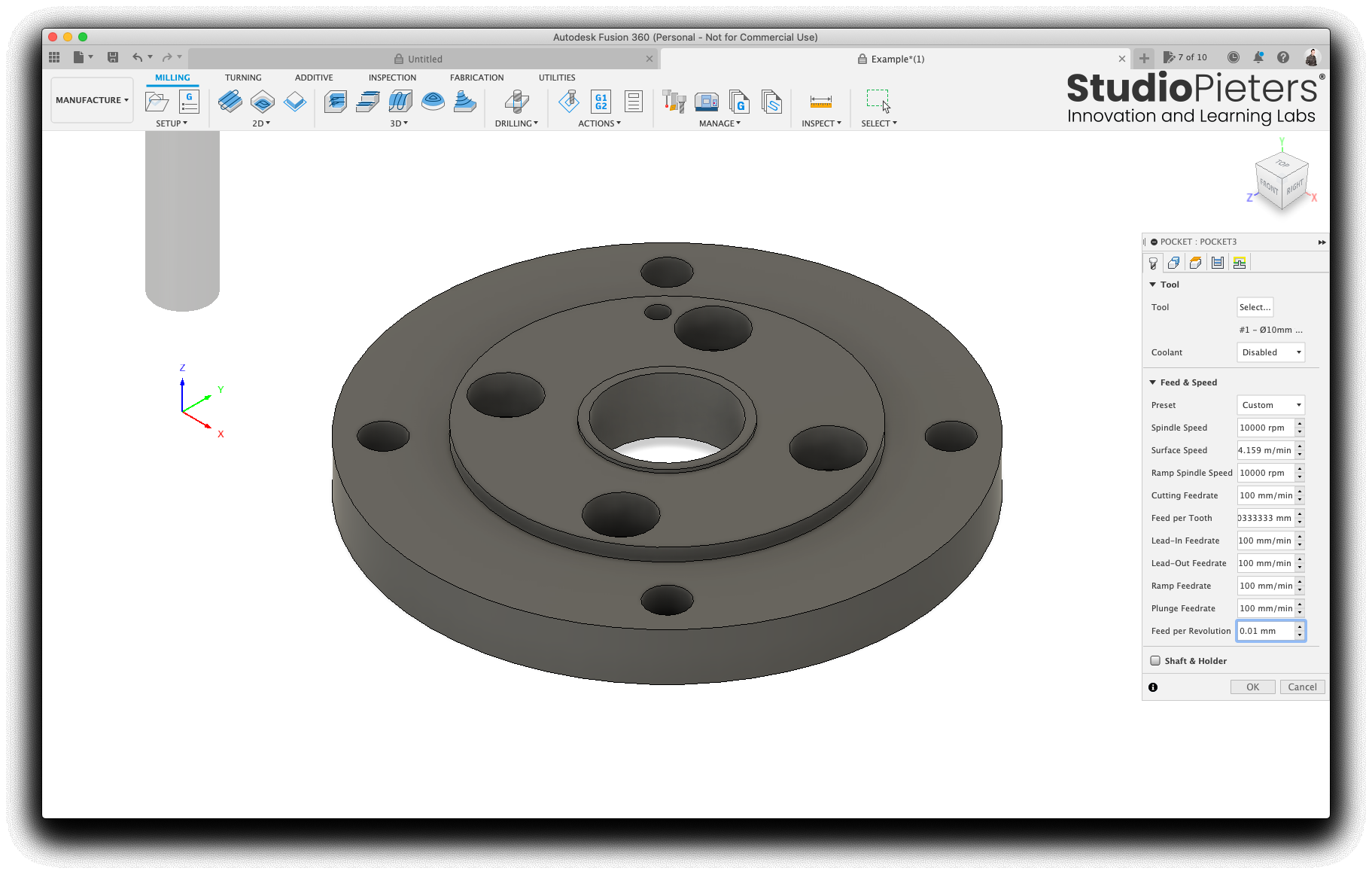
Set the feed rates for the operation, I dial these ways back to 100 mm/min for my little mill on acrylic. It’s too easy to break the tool otherwise.
Select the geometry tab, and change the Matching Boundary to Silhouette.
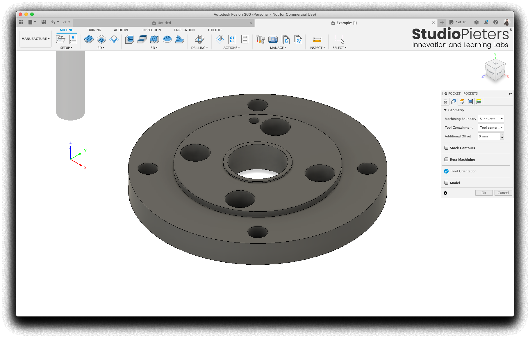
Press OK.
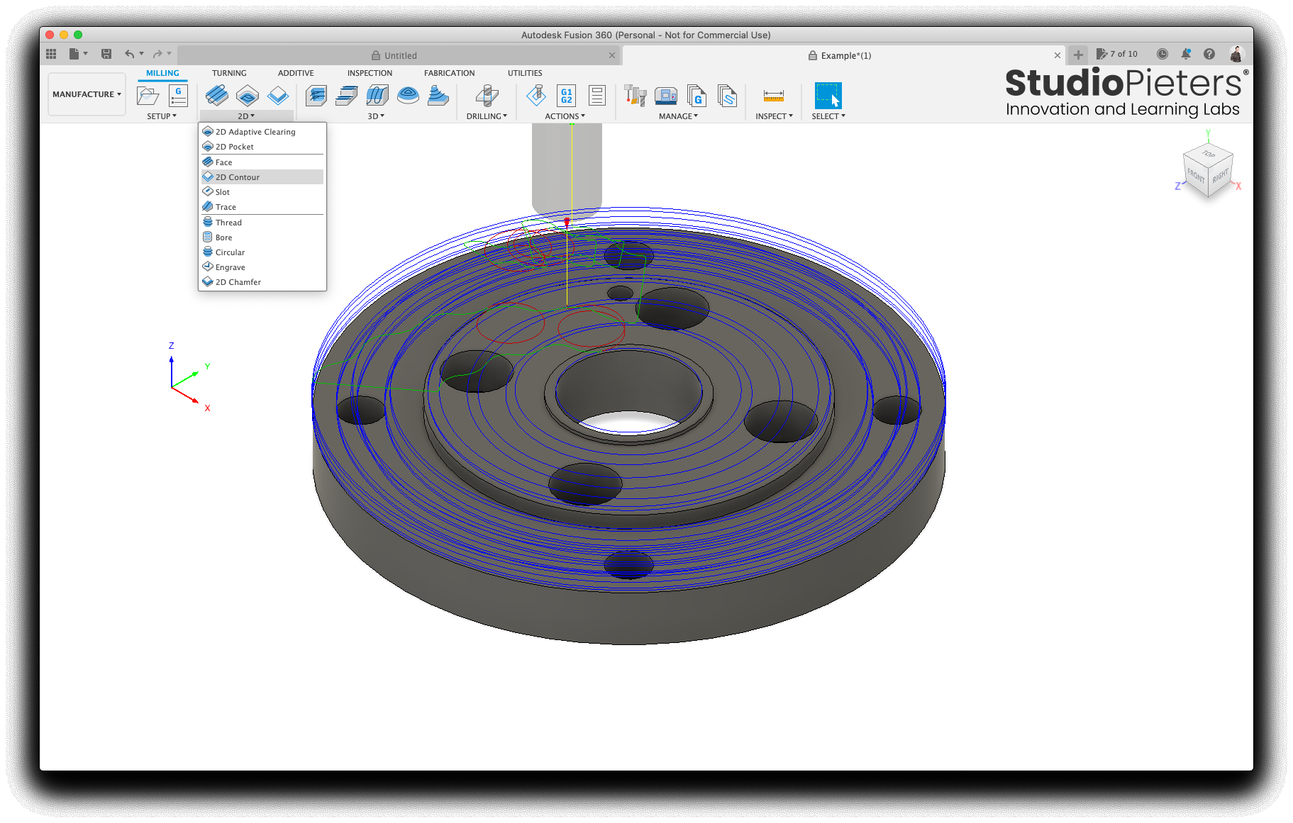
2D contour
The next operation for our mill is to cut the whole part out from the stock. Our shape is just a flat 2D part, so we can use a 2D contour for this.

Select the 2D menu and press 2D contour.
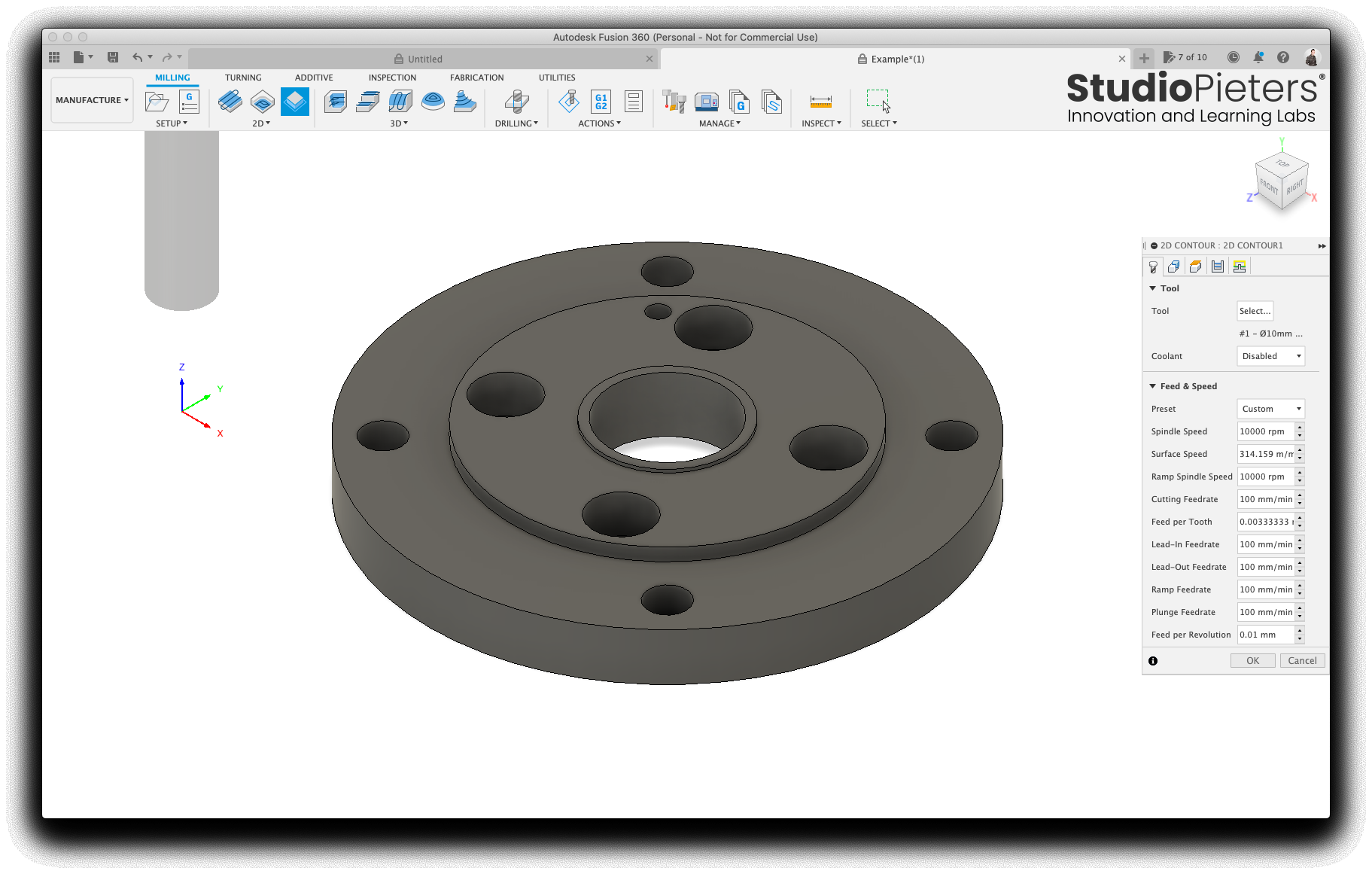
Fusion should remember the tool selection and feed rates, so nothing to change in the tool tab.
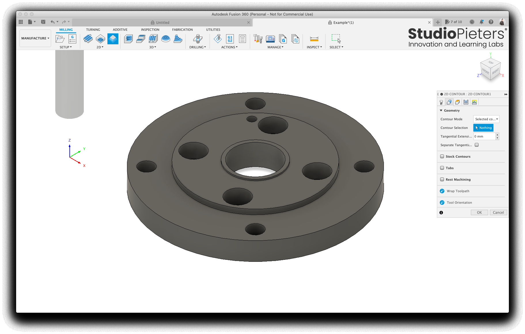
Select the geometry tab, click the button to the right of contour selection.
Select the BOTTOM edge of the part. If you select the top, you will only make a scratch in the top of the stock and won’t cut the part out completely.
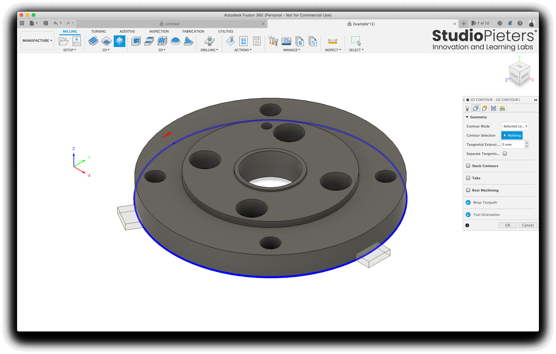
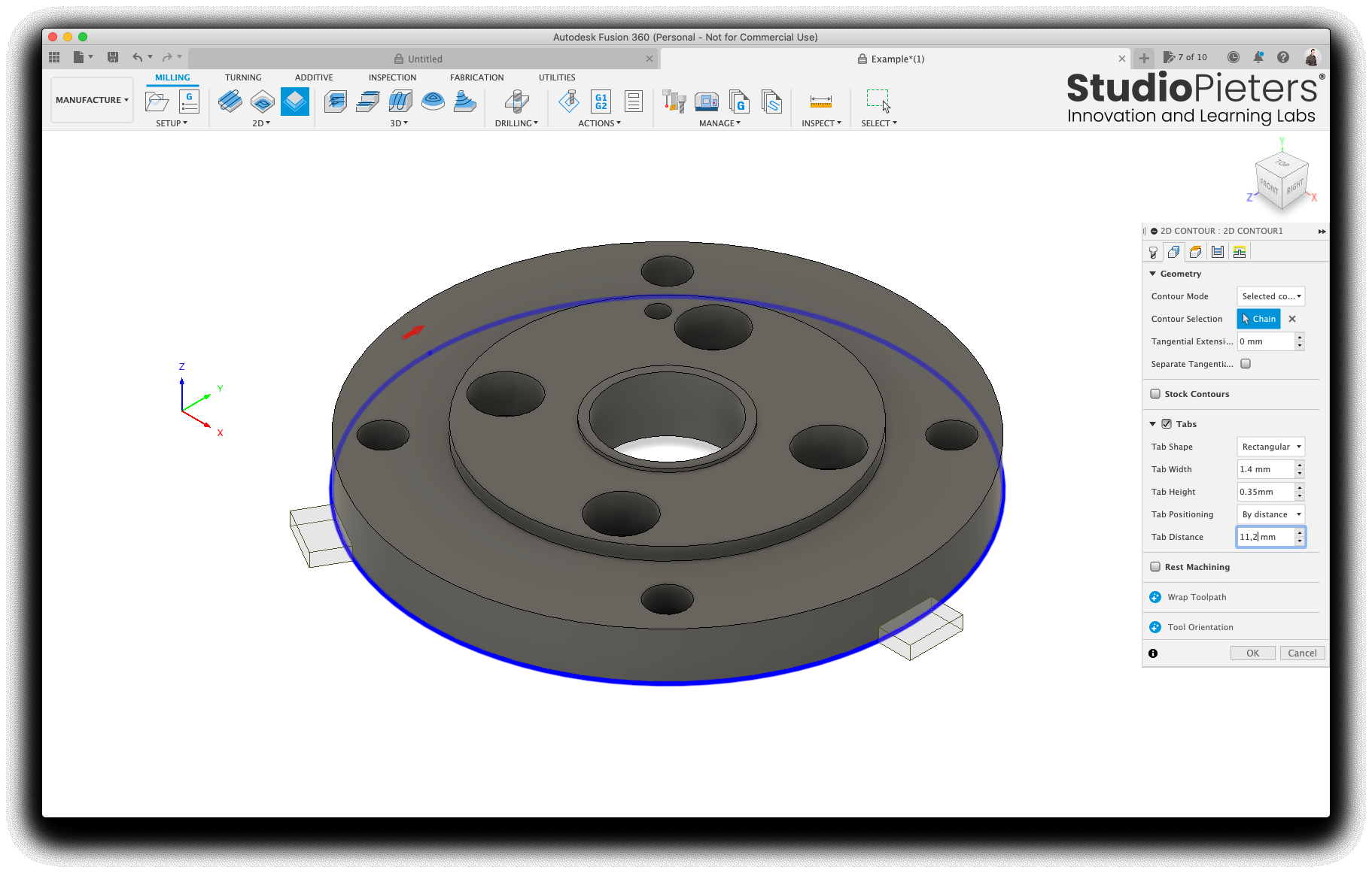
Select Tabs, these little things hold the part in place while milling to stop it flying away and getting damaged right at the end of the job. They are pretty easy to break away and sand off at the end.
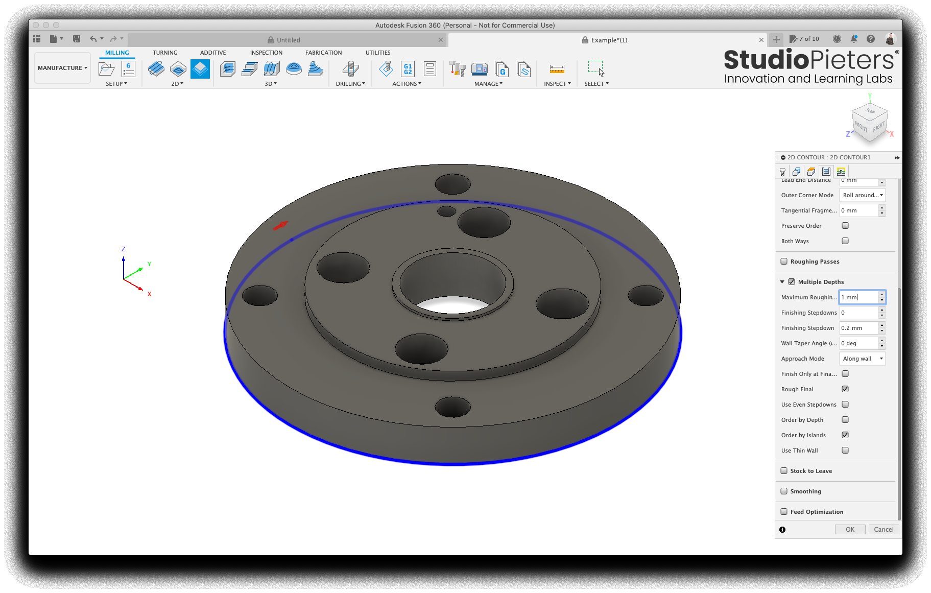
Select Passes tab and enable multiple depths. For my little 3018CNC mill, I can’t really take away more than a 1 mm of acrylic each pass. Press OK.
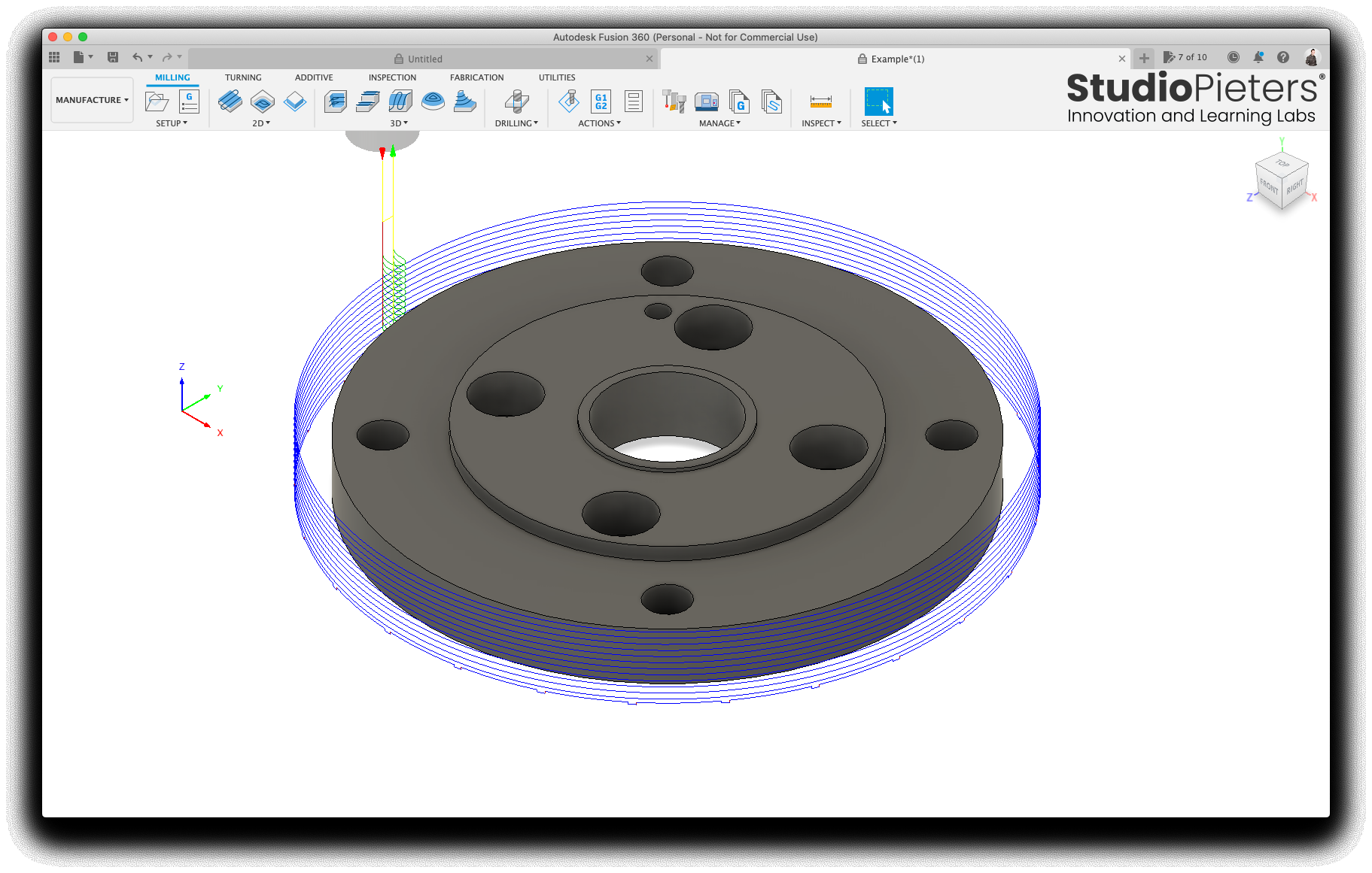
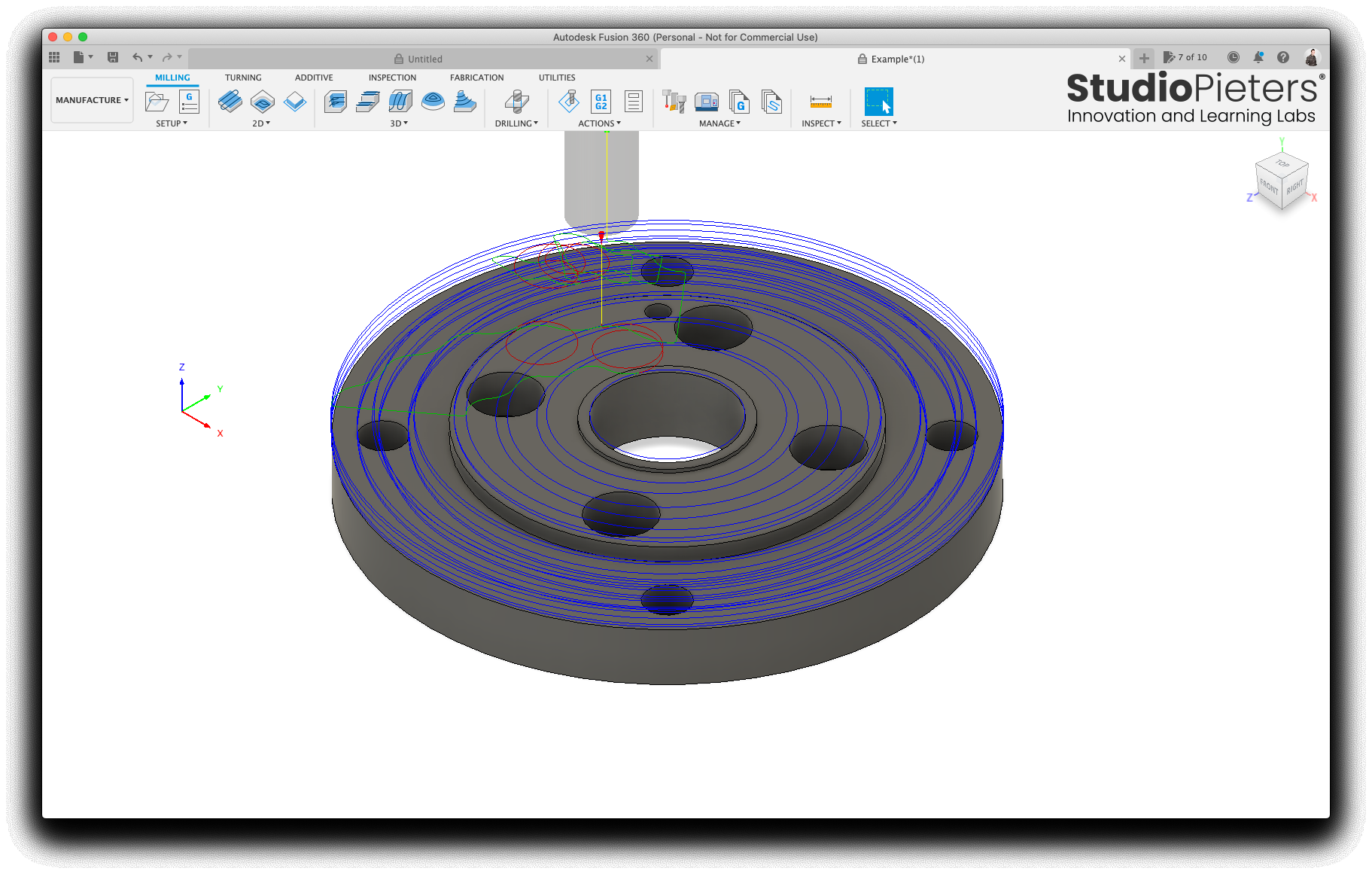
Simulation in Fusion
Now that our tool path is all defined, we can run a simulation in Fusion. It’s the button with an icon that looks a little joystick button in the top menu. I turn the stock on, so I can see fusion digitally carving away on the part. After you are happy that everything is working correctly, we can export the g-code.

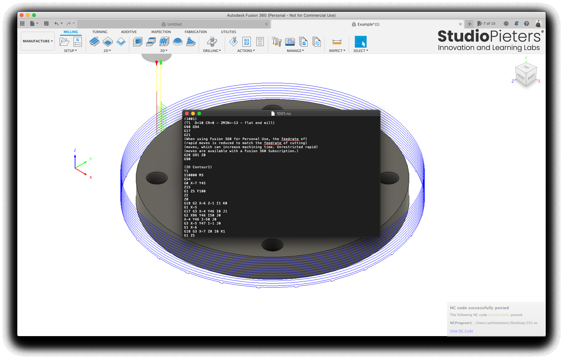
Right-click on your setup and select post-process. Select GRBL from the post processor drop down.
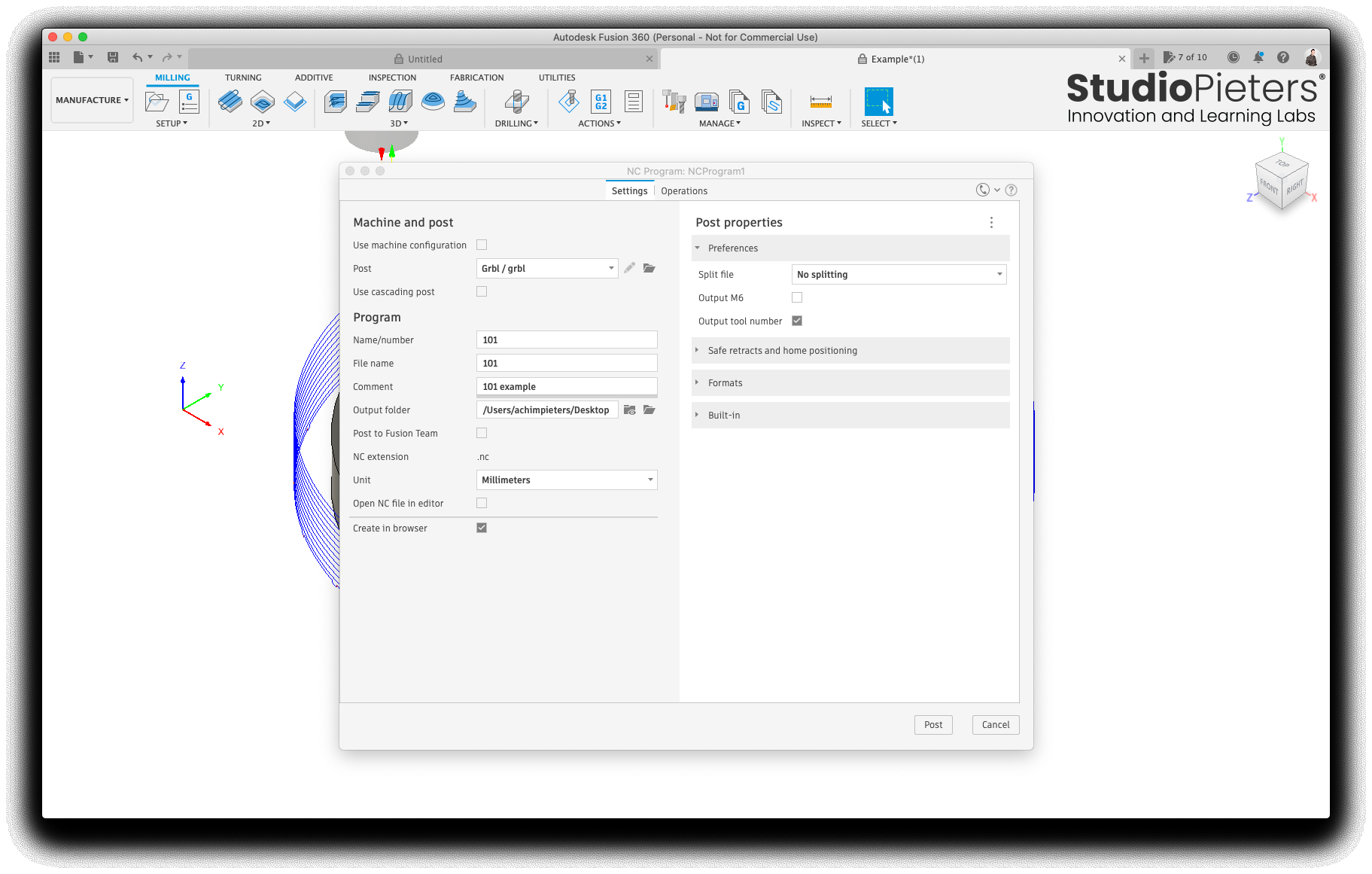
Press OK and tell fusion the filename for your g-code file. After Fusion has finished writing the file, you will be presented with an editing window filled with the completed g-code. You can close this if you don’t have any changes you want to make by hand.
That’s it, now you have a g-code file that can be loaded up in Octoprint or whatever else you are using to send commands to your GRBL powered CNC mill.

Reference
AutoCAD, Fusion 360, Fusion 360 is a cloud-based 3D modeling, CAD, CAM, CAE, and PCB software platform for product design and manufacturing, https://www.autodesk.com/products/fusion-360 Reprage, How to export g-code from Autodesk Fusion360 for generic 2418 CNC mills, https://reprage.com/post/fusion360-to-gcode-to-grbl-CNC-mill