CNC – 3018 Pro Assembly
Finally It’s here my CNC 3018 Pro Router! I came really fast within one week. Time to see what is in the box and then assembly af de CNC 3018 Pro Router. Hope you enjoy this blog.

Unboxing
The box it gets delivered inside a brown box and is surprisingly compact. It measures approx 430 x 220 x 200 mm. The contents are well packed in soft foam that is shaped to fit the components. The first parts I pulled out were these two small stepper motors. There is a third stepper motor already mounted on the spindle assembly. As you can see these a ‘standard’ Nema Motors as you also can find on 3D printers.

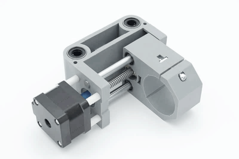
Here is the spindle mount assembly. It is constructed from a hard plastic, possibly ABS. I had read other reviews that suggested the plastic parts on these machines were 3D printed, but these were made in a plastic injection mold tool. The ejector pin marks are clearly visible.
The spindle motor comes with an ER11 collet extension already attached, complete with a 1/8″ ER11 Collet. ER11 series collets have a capacity of .020-.3125 inches. Each ER11 collet has a range of .020 inches(0.5mm). The size indicated on the collet is the largest size it can hold and can be collapsed smaller within its collapse range of .020 inches(0.5mm). For example, ER11-3mm can grab a round shank from 3mm diameter to 2.5mm diameter.

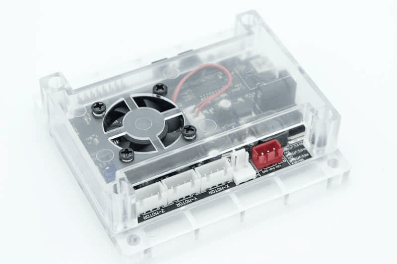
There is a 24V power supply, which looks very similar to a laptop power brick. and is a default Power supply. The control board comes mounted inside a clear protective case with a built in cooling fan. In the image you can see the connection points for the stepper motors and spindle. There is also an ‘offline controller’ supplied that can be used to manually move the machine for setting up your datum positions. Programs can also be ran from this using the supplied micro USB card, but I didn’t order that one.
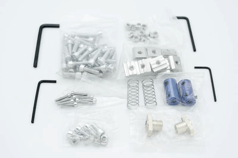
There are a couple of packs of hardware included, one with the screws to build the machine and another pack with clamps for work holding. The added engraving bits are identical and not very useful for general milling. And there is a bag of cables for the stepper motors and the spindle, and some small zip ties.
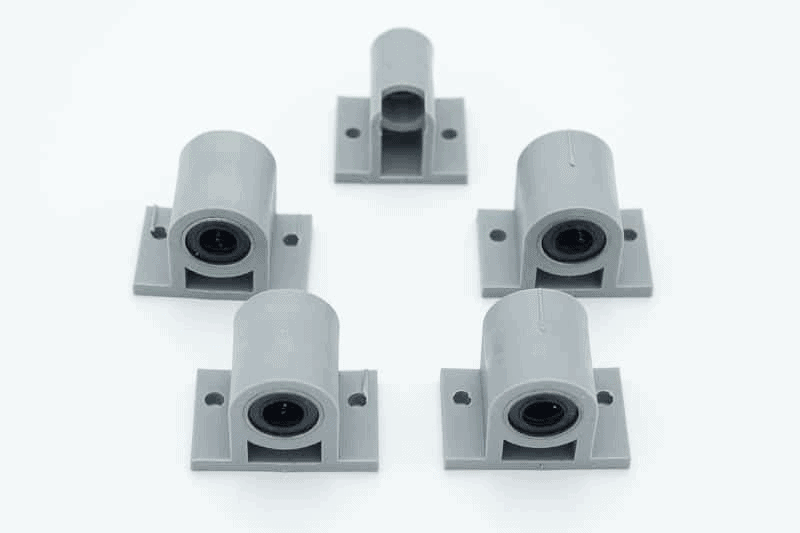
There are a set of four ‘Y axis sliders’ which bolt to the underneath of the table and a ‘Y axis nut seat’. These are also made from injection moulded plastic. These sliders have to be the most disappointing parts in the kit. The base of each part is badly warped and one has lumps on it that need removing so that it can be mounted properly. The injection mold tool used to make these parts was clearly damaged and poorly made. The warping is probably due to the mold not being cooled properly during use.

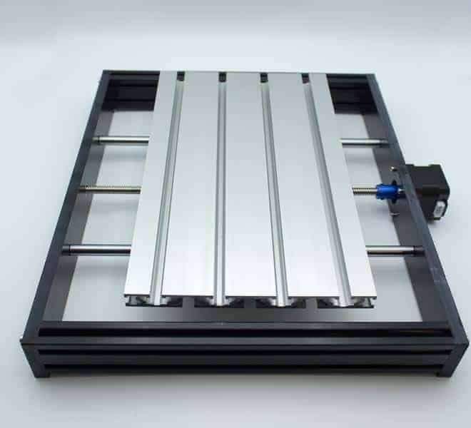
Next out of the box is the mill table. It is made from an aluminum extrusion and appears to be of good quality. This was covered in a protective film.
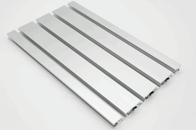
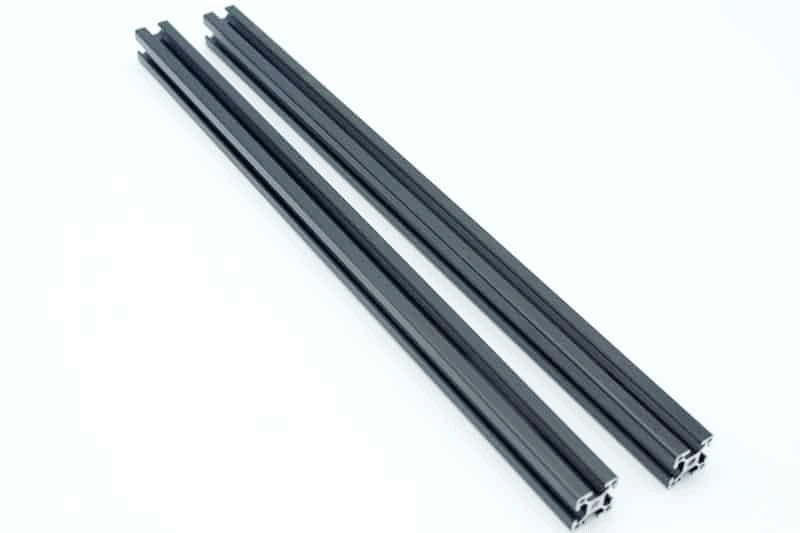
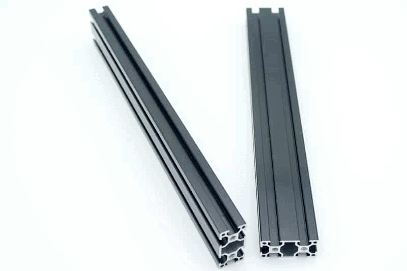
Next out of the box are the structural components of the mill. These consist of aluminum extrusions for the sides and vertical cross braces. Although the aluminum extrusions are of good quality they are shipped full of chips from being drilled and tapped. These all need cleaning out, especially from the threads so they don’t get damaged when you assemble them.
 |  |
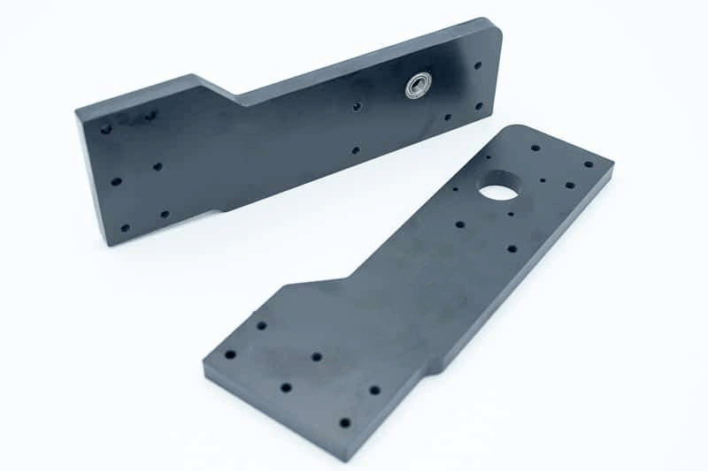
The remaining structural components are made from Bakelite. These parts are for the front and back of the base structure and the vertical sides that support the spindle assembly.
 | |
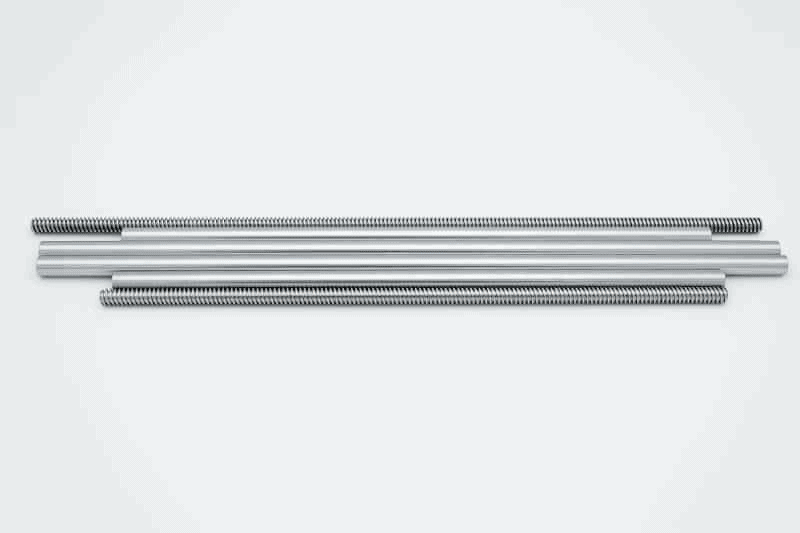
These are the two leadscrews and the ground bars that the table and spindle travel on. These all appear to be very good quality.
You will also receive a small manual, which is as short as possible.

CNC 3018 Pro Assembly
Of course we start at Step 1 in the manual. The construction of this machine is very straightforward, there are a few areas to be careful with, which I will point out when needed. For step 1 you need to clean the chips from the ends of the extrusions and remove the lump(s) from the base of the ‘Y axis sliders’. There is some flash on the moldings that need removing as well. The emphasis here is to make them sit flat on the bottom of the machine table. I did not do anything about the warping on the base of these parts, when they are clamped to the machine table they flatten out.
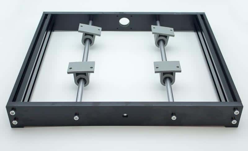
Step 2 consists of adding the Y axis leadscrew and the machine table. There is an extra ‘copper nut’ to add to the Y axis nut seat, this is added along with a spring. The spring adds pressure between the two nuts pushing them against the leadscrew threads to prevent the table from rattling.
 |  |
Position the stepper motor with the connection point to the side. When clamping the Y axis sliders to the base of the machine table, it is a good idea to set the table square to the frame. I did this by sliding the table forward and trapping two blocks between the table and the frame. Then tightening the bolts to lock the table to the sliders.
 |  |
Step 3 consists of adding the first Bakelite vertical support. The support is positioned 46.5mm from the inside of the back frame. This dimension is not critical but when you add the second support it needs to be the same distance.
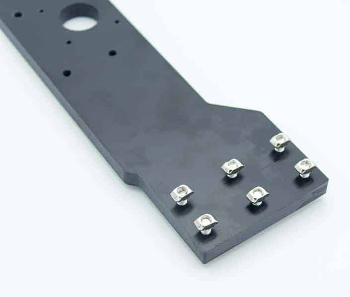
The t-nuts added to the vertical support. If you don’t have any measuring callipers to match the two distances you can find something to hold between the frame and support. A small wooden dowel cut to length could be used, just set it in the groove of the extrusion and push the support against it while the bolts are tightened. Then repeat with the same dowel on the other side.

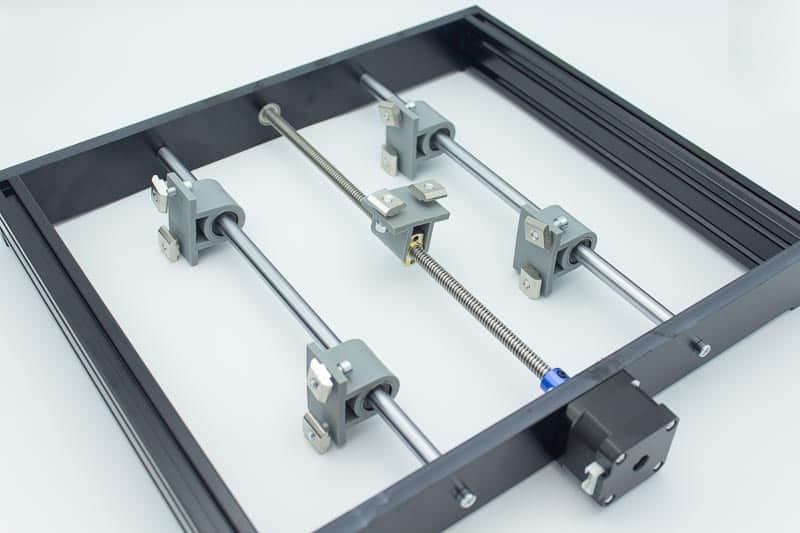
In step 4 you need to add the cross supports and ‘slide rods’ to the vertical support. I didn’t finish tightening the bolts until the other vertical support was added. The lead screw can be threaded in after the second vertical support is added.

Step 5 in the manual. In this step you add the second vertical support. It is important to position this the same distance away from the rear cross member as the other side. Use calipers or a short dowel as mentioned earlier. When these are tight, the support bars the spindle slides on can be tightened. I tightened the right hand bolts with the spindle assembly moved over to the right. This ensures that the bars are set at the correct distance apart. This was repeated on the left side by sliding the spindle assembly to the left before tightening the left side bolts. Then the X axis leadscrew can be added and the stepper motor can be bolted to the vertical support.
Step 6 is just sliding the spindle motor into the Z axis assembly. The bolt needs loosening off and the molding needs prying apart. The motor is reassuringly tight in the assembly, even with the bolt loose.

Step 7 consists of bolting the control board to the back of the horizontal cross braces.


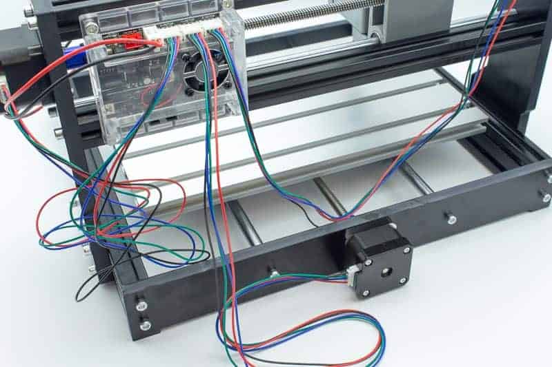
The last step of the build is to attach the cables from the control board to the stepper motors and spindle motor. The manual shows a picture of the board and where each connection is located.
Here’s a video go my whole building proces, enjoy!
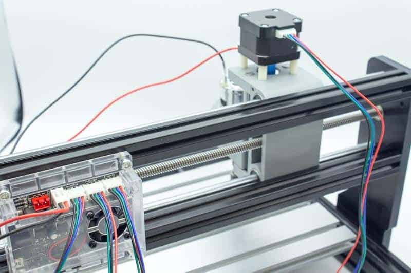
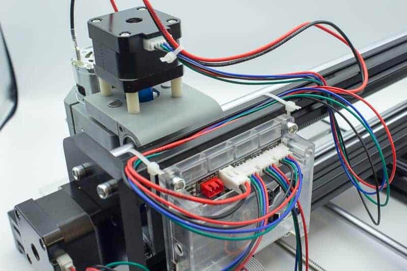
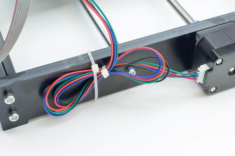
Adding the wiring
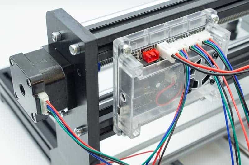
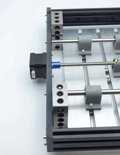
A view showing the X axis stepper motor now plugged in to the control board The X axis stepper motor is mounted on the vertical support, the Y axis motor is mounted at the back moving the table.
|  |
 |  |
 |  |
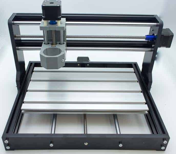
The finished machine ready for testing & learning!

Conclusion
It works, I can say that much… I found it really easy to use the GBRL candle software, I set up the tool, set the datum and it ran when I sent the program to the machine. This machine is probably about as easy an introduction to CNC machining you can get, at a really affordable price.
The only Negatives to the 3018 CNC machine is that it vibrates, constantly. I’m sure this is normal for this type of machine. It vibrates when engraving a piece of plywood with a tiny tool, cutting only .015″ deep. Although it wasn’t as bad when I used a decent ball end cutter. I have only tried a few simple programs so far, I am going to try more involved projects in the future to see what can be done on this machine.
Do I recommend a beginner buying one of these machines? Yes, if you are aware of its limitations and want to use it to learn and try some basic projects, it is perfect for this. It is fun and easy to use, it has a really simple construction and should be straightforward to fix, if and when parts wear out. There are several upgrade parts available. Inexpensive and educational are its main selling points.
Where to Buy
There are a few reliable places to get a CNC 3018 or its upgraded Pro version. We recommend purchasing from a reputable seller that offers warranties and easy replacements. Some retailers even have technical support available! I bought Mine at Aliexpress You can use the buy Botton below, this is a affiliate link, more information about affiliate links can be found here!


REFERENCE
All3DP, The CNC 3018 (Pro) Buyer’s Guide (2020), Nowadays, lots of hobby machines are operated through computer numerical control (CNC), https://all3dp.com/2/cnc-3018-pro-buyer-s-guide SainSmart ,CNC Router 1810-PRO DIY Kit (2020), affordable CNC Router Kit, the 1810-PRO boasts the same outstanding performance as the 3018, in a compact and affordable package., https://www.sainsmart.com/collections/cnc-machines/products/sainsmart-genmitsu-cnc-router-1810-pro-diy-kit cncphilosophy, CNC 3018 (2020), The mill or router isn’t the only piece of equipment you will need and there is a steep learning curve if you have no previous experience., https://cncphilosophy.com/3018-cnc