If you’ve worked on electronic projects in the past, you’ve probably heard of breadboards before, and maybe even used them. But what does ‘breadboard’ mean? Breadboards can be a little confusing at first if you don’t understand the logic behind them – which is exactly why we came up with this blog to get you started with your breadboard. We’re going to briefly explain how breadboards are built and how they work, how to connect components to the breadboard, where they get power from, what types of breadboards are out there, and how to use a breadboard with your StudioPieters® project.

Breadboard
A breadboard is a rectangular board with many mounting holes. They are used for making electrical connections between electronic components and single board computers or microcontrollers such as an Arduino and ESP32 development board. The connections are not permanent and can be removed and reinserted. You can even replace components to customize your project or work on a completely different project, using the same breadboard.
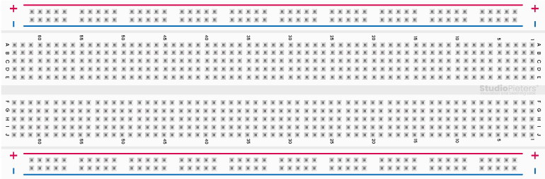
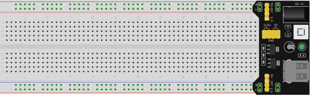
The vertical columns of the breadboard are calledTerminals, while the horizontal long rows are called Power rails because they are usually used to connect power to the breadboard. The positive rails are indicated by Red lines, while the negative rails are indicated by Bleu lines.
Breadboards are used to help you connect components to complete your basic circuit. The reason it is called breadboard dates back to the time when electronic components were much larger and people actually used wooden breadboards (boards used to cut bread) to connect electronic circuits. Fortunately, things have changed since then and only the name has been preserved. Breadboards are sold separately by most electronics distributors, and they also appear in most basic electronics kits you buy.

Breadboard connections
A breadboard connection to an electronic component is made using bone-like structures made of metal. These are called “leads” and can vary in size. The shorter ones are often called pins. So if your electronic component has cables, it can be plugged directly into the breadboard. DIP-based (that’s a double inline package) integrated circuits are built to fit perfectly into a breadboard, with each pin fitting over a breadboard hole.
These cables can be pushed into holes designed to hold them in place and prevent them from coming loose or falling out of the breadboard. You can even hold the breadboard upside down and these connections wouldn’t come loose. They are tight enough to fit and remove, but not enough for breadboard connections to come loose on their own.
The tightness comes from the fact that breadboards have little metal clips hidden under these holes, which hold everything in place. They basically grab onto the leads you insert. Aside from that, breadboards usually also have a backing to hold the clips themselves in place. This backing is normally made of double sided tape. One side of the tape is usually covered to avoid exposing the sticky layer.
However, if the breadboard needs to be attached to your electronic project, you can take this cover off and use the other sticky side. The next thing to notice on a breadboard are the markings such as letters, numbers, and symbols. The way these marks are laid out can vary from breadboard to breadboard. But the goal is all the same. These markings help users find the exact holes they need to connect the components. The closest example of this is an Excel spreadsheet. You have cells, rows and columns. The row number and respective column letter tell you which cell to look at. It’s almost the same with breadboards.

For example, C12 refers to the breadboard hole under column C and in row 12.

Breadboard power supply
There are plenty of ways to power a breadboard. For starters, you can always borrow power from development boards like Arduino or ESP32 development board. Arduino boards come with female headers from which power can be drawn. You have a series of ground and power pins that connect to the power rows of a breadboard. The Arduino board itself gets power from an external power source connected to the circuit. This can be a battery or a USB port.
Apart from that, you have binding messages on certain breadboards. These posts need to be connected to the board using jumper cables first and then you connect wires to the binding posts. Other than that, you have breadboard power options, such as a benchtop power supply and specialty power supplies built exclusively for breadboards. These units usually come as part of a breadboard kit. Some let you get power directly from a wall unit or from your computer via the USB port.

One of the common breadboard power supplies is a printed circuit board that plugs into the top of a breadboard. This module supplies power through the breadboard power rails. These modules can be either in 3.3V or 5V dual output fixed configurations. There are also a few with variable power supplies. This can be useful if you need more than 5 V.
How do you use a breadboard
Now that you have a basic idea of a breadboard, the next step is to actually learn how to use it. The way breadboards are used can vary depending on the specific project you are working on. So to give you a practical example of how a breadboard works, let’s use a small circuit as an example. As example we use a standerd Built-in Example from Arduino called, Blink.
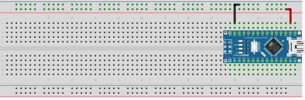
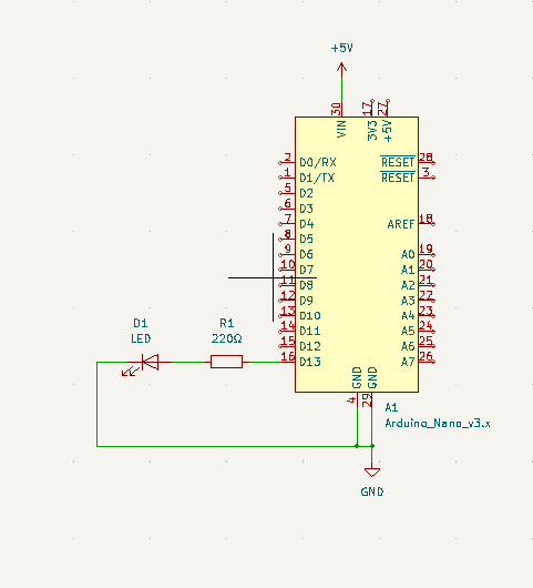
If you want to lit an external LED with this sketch, you need to build this circuit, where you connect one end of the resistor to the digital pin correspondent to the LED_BUILTIN constant. Connect the long leg of the LED (the positive leg, called the anode) to the other end of the resistor. Connect the short leg of the LED (the negative leg, called the cathode) to the GND. In the diagram below we show an UNO board that has D13 as the LED_BUILTIN value.
The value of the resistor in series with the LED may be of a different value than 220 ohm; the LED will lit up also with values up to 1K ohm. The whole project can be found here. You can use a Fritzing diagram to get a clear idea of how to make the circuit.
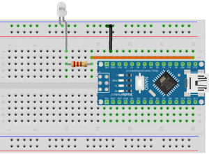
You can also refer to this image. Of course, you don’t have to follow the diagram exactly as it is. You can make changes as long as the circuit is “electrically equivalent“. That means the electricity has to flow through a closed circuit, allowing it to function as intended.
Types of breadboards
Today’s breadboards are made from a variety of materials and they also vary in size and shape. Larger breadboards are great for prototyping complex projects; mini breadboards are suitable for smaller ones.
However, if you were to divide breadboards into broader categories, you’d end up with two main types of breadboards: solderless and soldered. Solderless breadboards are what we’ve discussed so far and they’re the best option, especially if you’re a beginner. They are called “solderless” because there is no soldering required to make connections or hold things in place. For those wondering what soldering is, it is a method of joining electronic components together by melting a metal known as solder. The molten solder conducts electricity, which helps make the circuit, and it fuses with the connected ends to hold the connection together.
Which brings us to the topic of soldered breadboards. These are breadboards to which the connections are soldered. There are no metal clips to hold the leads. Soldered breadboards are rarely used. In fact, soldering is usually done on PCBs or printed circuit boards. Before that happens, engineers or technicians will actually use a solderless breadboard for prototyping. They don’t switch to a soldered circuit board until the prototype is a success. So these are the two main breadboards you’re likely to encounter.

Color jumper wires
Does it matter which color jumper wires I use on my breadboard. The simple answer to this question is “no”. Jumper wires are all the same. However, to avoid confusion, it is recommended that you use one set of wires of the same color for “+” terminals and one set of a different color for “–” terminals.

It’s even better if you use red wires for “+” connections and blue or black for “–” connections.
You may ask if it’s important to use a specific breadboard hole when making connections? The hole doesn’t matter as long as you use one that is on the same busbar or terminal strip. This is because the busbars are linked together and so are the terminal blocks. So the current and conductivity are kept within a specific strip.

However, if you were to jump to another terminal block or busbar, you would see a problem with your connection.
The horizontal, the “–” and “+” busbars, rails work in much the same way. They are all connected together and are used to connect the positives and the negatives. Note, however, that the busbars on either side of the breadboard are not connected. So if you must use both busbars, make sure that both are connected to the breadboard’s main power supply (and thus to each other).
Prototype to product
As we mentioned before, breadboards are used to create prototype circuits. Once you’ve tested a prototype and it turns out to be successful, the next step is to proceed with making a PCB (Printed Circuit Board). Breadboards are temporary and they will always be disconnected, which isn’t helpful if you’re going to build a device that needs the connections to stay undisturbed. This is where PCB’s come in handy. The connections in a printed circuit board are soldered and therefore permanent. Breadboards are mainly used as a planning tool for PCB manufacturing. This will allow you to test the basic layout of your electronic circuit and tell you where to place a particular part and how to wire it up.
You can use Fritzing Fab for this. Fritzing Fab is an online tool that allows you to create real PCB’s from your fritzing sketches. PCB’s are quite complex and the kind of people who work on them are usually electricians and other experienced individuals who have been working on circuits for a long time. One of the most popular tools used to design PCB’s is KiCAD.

Conclusion
We hope you found this guide helpful and that you now have a better understanding of what breadboards are and how to use them. As we mentioned before, breadboards are not complex devices. They may be a little confusing at first, but they are far from complicated. All you have to do is learn about it and after that things get super easy.
We invite you to take the information in this guide and buy a basic electronics kit and build your own project, because that’s the best way to learn (in our opinion, of course). Take the time to learn about breadboards by incorporating them into your electronic circuit projects. Or search for projects that require extensive use of breadboards. Breadboards are an incredibly useful tool for prototyping, and the more you use them, the more you get!

Reference
Fritzing, Fritzing is an open-source hardware initiative that makes electronics accessible as a creative material for anyone, https://fritzing.org Circuit.io, online circuit builder gives you wiring, code and IoT solutions for Arduino projects. Purhcase your components directly with us so you can quickly and effortlessly start prototyping., https://www.circuito.io/blog/breadboards/ Arduino, Arduino is an open-source electronics platform based on easy-to-use hardware and software. It’s intended for anyone making interactive projects., https://www.arduino.cc/en/Tutorial/BuiltInExamples/Blink KiCAD, KiCad is an open source software suite for Electronic Design Automation (EDA), https://www.kicad.org