
Reference
Seeed Studio XIAO ESP32S3 Pinout
The real pin reference for Seeed Studio's XIAO ESP32S3: thumbnail-sized, native USB, with a camera/display connector on the Sense variant.
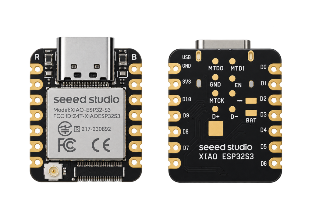
The XIAO ESP32S3 packs an ESP32-S3 into Seeed’s same 21×17.8mm XIAO footprint as the XIAO ESP32C3. It comes in a plain version and a “Sense” version that adds an onboard microphone and a camera/expansion connector. Pin data below is sourced from Seeed’s own wiki.
System-on-chip
The ESP32-S3 is the same dual-core Xtensa LX7 chip covered on this site’s AI-S3 page, Wi-Fi 802.11 b/g/n, Bluetooth 5 LE, and native USB. The XIAO board exposes 11 regular GPIOs plus JTAG pins, with an onboard status LED and a separate charge-status LED.
GPIO reference
| XIAO pin | GPIO | Function | Notes |
|---|---|---|---|
| D0 | GPIO1 | ADC, touch | |
| D1 | GPIO2 | ADC, touch | |
| D2 | GPIO3 | ADC, touch | |
| D3 | GPIO4 | ADC, touch | |
| D4 | GPIO5 | I²C SDA, ADC, touch | |
| D5 | GPIO6 | I²C SCL, ADC, touch | |
| D6 | GPIO43 | UART TX | |
| D7 | GPIO44 | UART RX | |
| D8 | GPIO7 | SPI SCK, ADC, touch | |
| D9 | GPIO8 | SPI MISO, ADC, touch | |
| D10 | GPIO9 | SPI MOSI, ADC, touch |
Boot: GPIO0 (hold low at power-on to enter the bootloader). Reset: CHIP_PU. Onboard user LED: GPIO21. Charge LED: a separate, non-GPIO indicator for USB charging status.
"Sense" variant: camera and microphone
The Sense variant adds a PDM microphone (data on GPIO42, clock on GPIO41) and a B2B expansion connector carrying a DVP camera interface (GPIO10–18, 38–40, 47–48) plus an SD-card SPI interface (GPIO7–9, 21), shared with the main header pins above, don’t assume both the camera/SD card and the main header are simultaneously free for other uses. If your board doesn’t have the extra connector on the underside, you have the plain (non-Sense) variant, and none of this section applies.
Conclusion
The XIAO ESP32S3 gives you native USB and more compute than the XIAO ESP32C3 in the same tiny footprint, plus a real camera/microphone path on the Sense variant. For a full-size breakout with two USB-C ports instead, see the AI-S3.
Related
 Reference
INA219 / INA226 Voltage, Current and Power Sensor Complete Guide
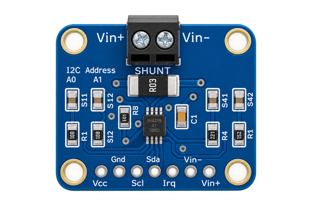
The INA219 and INA226 measure voltage, current and power on a low-voltage DC bus over I2C, using a shunt resistor and Ohm's law, not the mains-AC energy-meter ICs this site already covers. This guide covers both chips' real specs, wiring one to an ESP32, and which to pick for a battery or power-budget project.
Read more
Reference
INA219 / INA226 Voltage, Current and Power Sensor Complete Guide
The INA219 and INA226 measure voltage, current and power on a low-voltage DC bus over I2C, using a shunt resistor and Ohm's law, not the mains-AC energy-meter ICs this site already covers. This guide covers both chips' real specs, wiring one to an ESP32, and which to pick for a battery or power-budget project.
Read more
 Guide
HC-05 Bluetooth Module Pinout
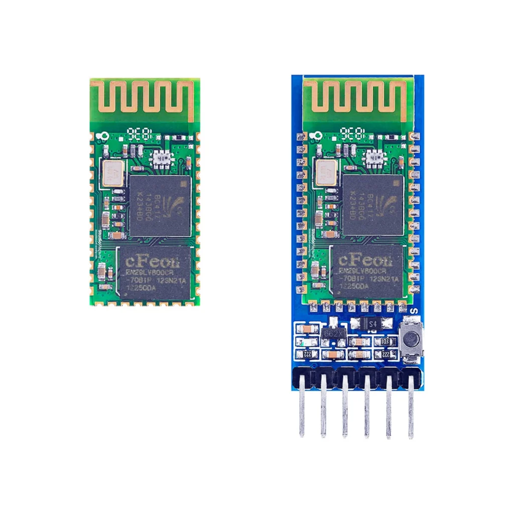
The complete pin reference for the HC-05: a UART-to-Bluetooth bridge available as a bare 34-pin module or a simple 6-pin breakout board.
Read more
Guide
HC-05 Bluetooth Module Pinout
The complete pin reference for the HC-05: a UART-to-Bluetooth bridge available as a bare 34-pin module or a simple 6-pin breakout board.
Read more
 Reference
ESP32 Dual Channel Relay Module
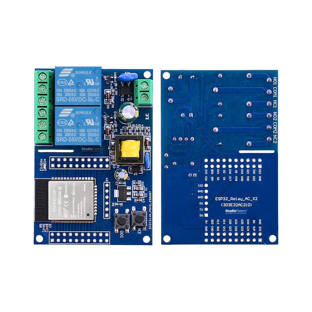
An ESP32-WROOM-32E module built onto a mains-powered dual-relay board, complete with galvanic isolation and an onboard 220V-to-3.3V power supply. This guide covers the pinout, both relay-control GPIOs, and how to flash it for Apple HomeKit.
Read more
Reference
ESP32 Dual Channel Relay Module
An ESP32-WROOM-32E module built onto a mains-powered dual-relay board, complete with galvanic isolation and an onboard 220V-to-3.3V power supply. This guide covers the pinout, both relay-control GPIOs, and how to flash it for Apple HomeKit.
Read more
More guides
Keep building.
From ESP32 HomeKit accessories to Arduino and ATtiny reference guides, there’s more where this came from.
All guides