
Reference
SSD1306 OLED Display
A tiny, self-illuminating I2C display for turning a headless ESP32 project into something readable at a glance. Covers the SSD1306 vs SH1106 offset trap, how the page-based framebuffer works, and avoiding burn-in.

The SSD1306 OLED display module is one of the easiest ways to add a crisp little screen to your ESP32 project. The module is based on the SSD1306 from Solomon Systech and gives you a bright, self-illuminating monochrome display over a simple two-wire I²C bus. Want to show your BME280 or DS18B20 readings without opening a serial monitor? This is the screen to reach for.
In this complete guide we cover:
- What the SSD1306 is
- Technical specifications
- Pinout (I²C breakout)
- I²C address selection
- OLED vs LCD – why OLED
- ESP32-C6 SUPER MINI wiring
- How the SSD1306 works (pages and the framebuffer)
- ESP-IDF example code (esp_lcd driver)
- Arduino example code
- SSD1306 vs SH1106 – the offset trap
- Burn-in and how to avoid it
- Practical engineering tips
What is the SSD1306?
The SSD1306 is a driver chip for small monochrome OLED displays, most commonly the 0.96-inch 128×64 panels you see on almost every maker’s desk. Each pixel is its own tiny light, so an OLED needs no backlight — black pixels are truly off, giving deep contrast and a wide viewing angle.
Key features:
- 128×64 (or 128×32) monochrome pixels
- Self-illuminating — excellent contrast, no backlight
- I²C or SPI interface
- Very low power, especially with mostly-dark screens
- Built-in display RAM — the ESP32 only sends what changes
- Tiny, cheap and universally supported
It’s the default choice for status readouts, sensor dashboards, menus, tiny games and any project that benefits from a glance-able display.
Technical Specifications
| Parameter | Value |
|---|---|
| Controller | SSD1306 |
| Resolution | 128×64 or 128×32 pixels |
| Colour | Monochrome (white, blue, or yellow/blue) |
| Panel size | Typically 0.96″ (also 0.91″, 1.3″) |
| Interface | I²C (or SPI) |
| I²C address | 0x3C or 0x3D |
| Supply voltage | 3.3V – 5V (board with regulator) |
| Display RAM | 1 KB (128 × 64 / 8) |
| Operating temperature | -40°C to +85°C |
⚠️ Many boards accept 3.3V–5V thanks to an onboard regulator, but the SSD1306 logic runs at 3.3V. On an ESP32 just power it from 3.3V so the I²C levels match perfectly.
Pinout
The common I²C breakout has just four pins:
| Pin | Description |
|---|---|
| GND | Ground |
| VCC | 3.3V supply |
| SCL | I²C clock |
| SDA | I²C data |
That’s it — four wires and you have a screen. SPI versions exist with extra pins (DC, RST, CS), but the I²C variant is by far the most common and the one we use here.
I²C Address Selection
Most SSD1306 boards are fixed to one of two addresses:
| Address | Notes |
|---|---|
| 0x3C | Default on almost all boards |
| 0x3D | Selectable on some boards via a jumper |
⚠️ The silkscreen sometimes prints 0x78/0x7A — those are the 8-bit addresses including the read/write bit. The 7-bit address your code needs is 0x3C (0x78 ÷ 2). If a scanner finds 0x3C, use 0x3C.
OLED vs LCD – Why OLED?
For a small status display, OLED beats a character LCD in almost every way:
| Feature | SSD1306 OLED | 16×2 Character LCD |
|---|---|---|
| Contrast | Excellent (true black) | Moderate |
| Backlight | None needed | Required |
| Graphics | Full pixel control | Fixed character grid |
| Viewing angle | Very wide | Narrow |
| Size | Tiny | Bulky |
| Power (dark UI) | Very low | Backlight always on |
The one place an LCD still wins is direct sunlight and sheer cheapness at large character sizes — but for a compact ESP32 project, the OLED is almost always the better pick.
Connecting to the ESP32-C6 SUPER MINI
Only four wires are needed:
| SSD1306 | ESP32-C6 SUPER MINI | Wire |
|---|---|---|
| VCC | 3V3 | Red |
| GND | GND | Black |
| SDA | GPIO6 | Green |
| SCL | GPIO7 | Yellow |
Notes:
- GPIO6 and GPIO7 are free, safe pins on the ESP32-C6 SUPER MINI — the I²C peripheral can be routed to any GPIO thanks to the ESP32 GPIO matrix.
- Avoid GPIO8: on most SUPER MINI boards the onboard RGB LED is connected there.
- The SSD1306 shares the I²C bus happily with other devices — you can run a BME280 and an OLED on the same two wires.
- The board carries its own I²C pull-ups, so no external resistors are needed for short runs.
How the SSD1306 Works
The 128×64 display is organised into 8 horizontal “pages”, each 8 pixels tall and 128 pixels wide. One byte sets a vertical column of 8 pixels within a page, with the least-significant bit at the top.
To draw anything, you:
- Build a framebuffer in the ESP32’s memory (1024 bytes for 128×64).
- Set the drawing area with column and page address commands.
- Stream the framebuffer to the display’s RAM over I²C.
Because the display keeps its own copy in RAM, you only send data when something changes — very efficient. The catch is that drawing text and shapes means manipulating individual bits in that buffer, which is exactly why a graphics library is so useful here.
⚠️ Unlike the simple register-based modules on this site, a bare SSD1306 needs font data and framebuffer logic to be useful. Below we lean on a driver/library rather than pretending it’s a couple of register writes.
ESP-IDF Example Code
On ESP-IDF the clean approach uses the built-in esp_lcd driver with its SSD1306 panel support, driving the modern I²C master bus. This sets up the panel and clears it; drawing text is then done with a graphics helper such as LVGL or u8g2:
#include "freertos/FreeRTOS.h"
#include "freertos/task.h"
#include "driver/i2c_master.h"
#include "esp_lcd_panel_io.h"
#include "esp_lcd_panel_ops.h"
#include "esp_lcd_panel_ssd1306.h"
#include "esp_log.h"

#define I2C_SDA_GPIO   6
#define I2C_SCL_GPIO   7
#define SSD1306_ADDR   0x3C
#define OLED_WIDTH     128
#define OLED_HEIGHT    64

static const char *TAG = "SSD1306";

void app_main(void)
{
    /* I²C master bus */
    i2c_master_bus_config_t bus_cfg = {
        .i2c_port = I2C_NUM_0,
        .sda_io_num = I2C_SDA_GPIO,
        .scl_io_num = I2C_SCL_GPIO,
        .clk_source = I2C_CLK_SRC_DEFAULT,
        .glitch_ignore_cnt = 7,
        .flags.enable_internal_pullup = true,
    };
    i2c_master_bus_handle_t bus;
    ESP_ERROR_CHECK(i2c_new_master_bus(&bus_cfg, &bus));

    /* Panel IO for the SSD1306 over I²C */
    esp_lcd_panel_io_handle_t io;
    esp_lcd_panel_io_i2c_config_t io_cfg = {
        .dev_addr = SSD1306_ADDR,
        .scl_speed_hz = 400000,
        .control_phase_bytes = 1,
        .dc_bit_offset = 6,
        .lcd_cmd_bits = 8,
        .lcd_param_bits = 8,
    };
    ESP_ERROR_CHECK(esp_lcd_new_panel_io_i2c(bus, &io_cfg, &io));

    /* Create the SSD1306 panel */
    esp_lcd_panel_handle_t panel;
    esp_lcd_panel_ssd1306_config_t ssd1306_cfg = { .height = OLED_HEIGHT };
    esp_lcd_panel_dev_config_t panel_cfg = {
        .bits_per_pixel = 1,
        .reset_gpio_num = -1,
        .vendor_config = &ssd1306_cfg,
    };
    ESP_ERROR_CHECK(esp_lcd_new_panel_ssd1306(io, &panel_cfg, &panel));

    ESP_ERROR_CHECK(esp_lcd_panel_reset(panel));
    ESP_ERROR_CHECK(esp_lcd_panel_init(panel));
    ESP_ERROR_CHECK(esp_lcd_panel_disp_on_off(panel, true));
    ESP_LOGI(TAG, "SSD1306 ready at 0x%02X", SSD1306_ADDR);

    /* Clear the screen: 128 x 64 / 8 = 1024 bytes, all zero */
    static uint8_t blank[OLED_WIDTH * OLED_HEIGHT / 8] = {0};
    esp_lcd_panel_draw_bitmap(panel, 0, 0, OLED_WIDTH, OLED_HEIGHT, blank);

    /* From here, attach LVGL or u8g2 to draw text and graphics. */
    while (1) {
        vTaskDelay(pdMS_TO_TICKS(1000));
    }
}
For text and shapes, add LVGL (rich UI) or u8g2 (lightweight fonts and primitives) on top of this panel — both integrate cleanly with esp_lcd.
Prefer Arduino?
The Adafruit SSD1306 + GFX libraries make text trivial:
#include <Adafruit_GFX.h>
#include <Adafruit_SSD1306.h>

Adafruit_SSD1306 oled(128, 64, &Wire);

void setup() {
  Wire.begin(6, 7);                    // SDA = GPIO6, SCL = GPIO7
  oled.begin(SSD1306_SWITCHCAPVCC, 0x3C);
  oled.clearDisplay();
  oled.setTextSize(2);
  oled.setTextColor(SSD1306_WHITE);
  oled.setCursor(0, 0);
  oled.println("StudioPieters");
  oled.display();
}

void loop() {}
SSD1306 vs SH1106 – The Offset Trap
This is the single most common surprise with cheap OLED boards, so it gets its own section.
⚠️ Many 1.3-inch displays sold as “SSD1306” actually use the SH1106 controller. The SH1106 has 132 columns of RAM instead of 128, so if you drive it as an SSD1306 you get a 2-pixel horizontal offset and a stripe of noise down one edge.
If your text is shifted 2 pixels and there’s junk on the left, you have an SH1106:
- In Arduino, switch to a library/driver that supports the SH1106 (e.g. u8g2 with the SH1106 constructor).
- In ESP-IDF/u8g2, pick the SH1106 device variant.
The panels are otherwise interchangeable — it’s purely a driver choice.
Burn-In and How to Avoid It
OLEDs are gorgeous but the pixels age. A static layout left on for weeks can leave a faint permanent ghost:
- Dim the display where possible (the SSD1306 has a contrast command).
- Sleep the panel when nothing needs showing (display off draws almost nothing).
- Move static elements a pixel now and then, or refresh the layout periodically.
- Prefer mostly-dark UIs — fewer lit pixels means slower ageing and lower power.
Practical Engineering Tips
1. Use the 7-bit Address
If the board says 0x78, your code wants 0x3C. Confusing the 8-bit and 7-bit address is the classic “nothing shows up” mistake.
2. Run an I²C Scanner First
Before any drawing code, scan the bus. If 0x3C appears, wiring is good. If not, check VCC/GND and SDA/SCL — the screen can’t complain, it just stays dark.
3. Share the Bus
The OLED coexists with other I²C devices. Show your BME280 or DS18B20 readings live on the same two wires — no extra pins needed.
4. Only Redraw What Changes
Update just the region that changed rather than pushing the whole framebuffer every loop. It’s faster and keeps the bus free for your sensors.
5. Know Your Controller
Before buying in bulk, confirm whether a board is a true SSD1306 or an SH1106 — it saves an afternoon of debugging a mysterious 2-pixel shift.
Conclusion
The SSD1306 OLED is a tiny module that transforms a headless ESP32 into something you can actually read at a glance. Combined with the ESP32-C6 SUPER MINI it’s the perfect front panel for a sensor node, a clock, a menu or a status display.
It offers:
- A crisp 128×64 monochrome display over just 2 wires
- True-black contrast with no backlight
- Low power, especially with dark layouts
- Shared I²C — runs alongside your sensors
- Broad library support (LVGL, u8g2, Adafruit GFX)
Where the BME280 and DS18B20 measure the world and the ADS1115 reads raw signals, the SSD1306 is how your project shows what it knows. For any ESP32 build that deserves a face, it’s one of the best-value building blocks you can add to your parts drawer.
Related
 Guide
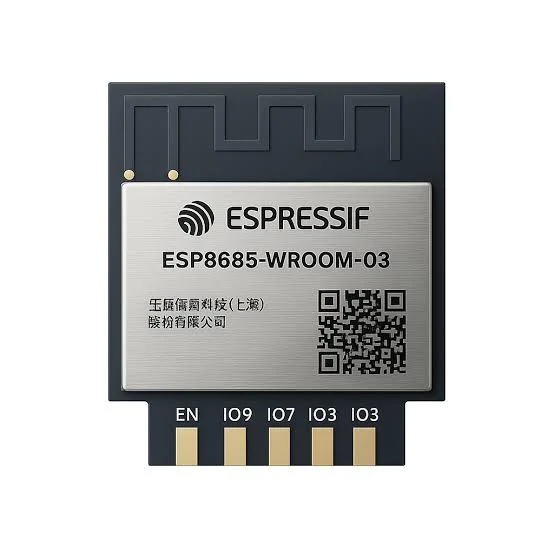
ESP8685-WROOM-03 Pinout
The complete pin reference for the ESP8685-WROOM-03 module: Espressif’s enhanced ESP32-C2-family chip in an 11-pin package, and the exact pins you can safely reuse.
Read more
Guide
ESP8685-WROOM-03 Pinout
The complete pin reference for the ESP8685-WROOM-03 module: Espressif’s enhanced ESP32-C2-family chip in an 11-pin package, and the exact pins you can safely reuse.
Read more
 Reference
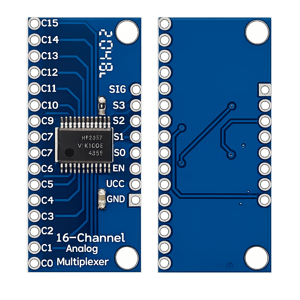
CD74HC4067 16-Channel Analog Multiplexer – Complete Guide
A 16-position analog switch controlled by just 4 GPIO pins, turning one ADC input into sixteen. This guide covers the pinout, channel-select truth table, ESP32 wiring, ESP-IDF/Arduino code, and how it compares to the 74HC4051 and the ADS1115.
Read more
Reference
CD74HC4067 16-Channel Analog Multiplexer – Complete Guide
A 16-position analog switch controlled by just 4 GPIO pins, turning one ADC input into sixteen. This guide covers the pinout, channel-select truth table, ESP32 wiring, ESP-IDF/Arduino code, and how it compares to the 74HC4051 and the ADS1115.
Read more
 Reference
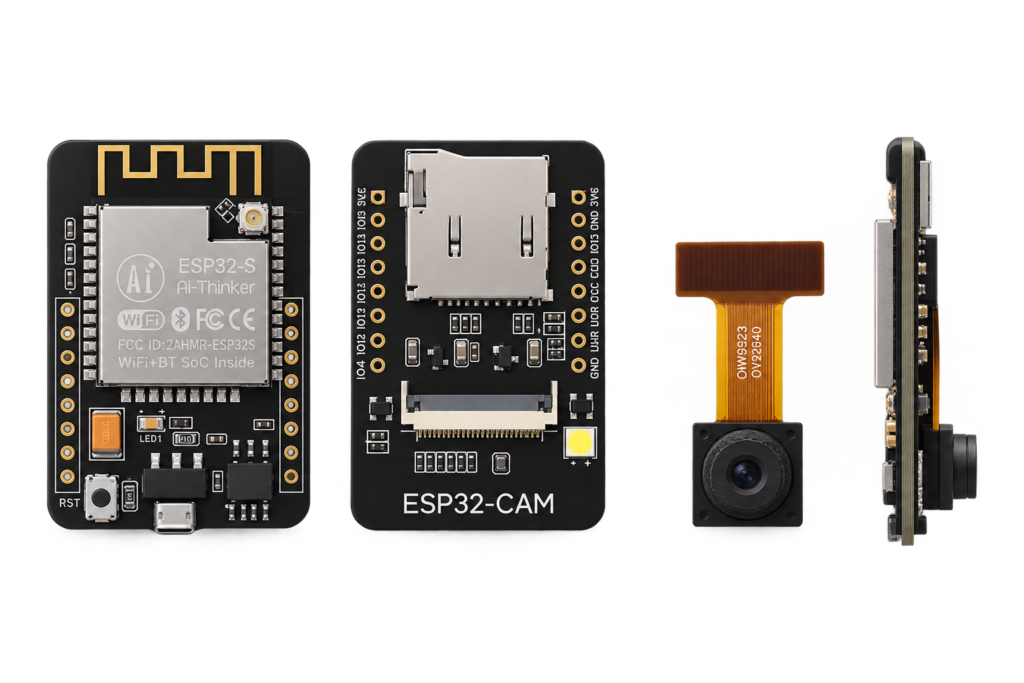
ESP32-CAM (AI-Thinker) Pinout
The real pin reference for the AI-Thinker ESP32-CAM: an ESP32 with a camera connector and microSD slot, and only 2 or 3 genuinely free GPIOs left over.
Read more
Reference
ESP32-CAM (AI-Thinker) Pinout
The real pin reference for the AI-Thinker ESP32-CAM: an ESP32 with a camera connector and microSD slot, and only 2 or 3 genuinely free GPIOs left over.
Read more
More guides
Keep building.
From ESP32 HomeKit accessories to Arduino and ATtiny reference guides, there’s more where this came from.
All guides