
Reference
ADS1115 16-Bit ADC
A precision 16-bit I2C analog-to-digital converter for when the ESP32’s own noisy 12-bit ADC is not accurate enough. Covers single-ended and differential inputs, the programmable gain amplifier, and reading a signed conversion result correctly.
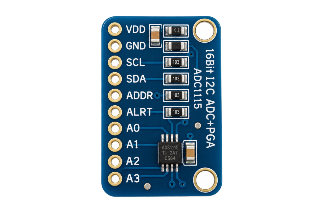
The ADS1115 16-bit ADC module is one of the easiest ways to add precise, low-noise analog measurement to your ESP32 project. The module is based on the ADS1115 from Texas Instruments and gives you four 16-bit analog inputs — with a built-in amplifier and a rock-stable reference — over a simple two-wire I²C bus. Tired of the noisy, non-linear readings from the ESP32’s own ADC? This is the fix.
In this complete guide we cover:
- What the ADS1115 is
- Technical specifications
- Pinout (ADS1115 breakout)
- I²C address selection
- Input overview – single-ended and differential modes
- The Programmable Gain Amplifier (PGA) explained
- ESP32-C6 SUPER MINI wiring
- Register map explained
- The Config register decoded
- ESP-IDF example code (single-ended read)
- Arduino example code
- Continuous mode and the ALERT/RDY pin
- ADS1115 vs the ESP32’s native ADC
- Practical engineering tips
What is the ADS1115?
The ADS1115 is a 16-bit, delta-sigma analog-to-digital converter controlled over I²C. It turns a real-world voltage into a clean digital number with far more resolution and stability than the ADC built into most microcontrollers.
Unlike the ESP32’s internal ADC, the ADS1115 includes:
- A true 16-bit delta-sigma converter
- 4 single-ended or 2 differential inputs
- A Programmable Gain Amplifier (PGA) from ±0.256V to ±6.144V
- An internal, calibrated voltage reference — no ratiometric drift
- An internal oscillator — no external clock needed
- A programmable comparator with an ALERT/RDY output
- Data rates from 8 to 860 samples per second
- Ultra-low current draw (~150 µA in continuous mode)
There is also a 12-bit, faster sibling — the ADS1015 — which is pin- and register-compatible. Most breakout boards can be populated with either chip, so always check which one you actually have.
Technical Specifications
| Parameter | Value |
|---|---|
| Resolution | 16-bit (delta-sigma) |
| Inputs | 4 single-ended / 2 differential |
| Interface | I²C (up to 400 kHz Fast-mode) |
| I²C address range | 0x48 – 0x4B (1 address pin, 4 options) |
| Supply voltage | 2.0V – 5.5V |
| PGA full-scale range | ±0.256V up to ±6.144V |
| Data rate | 8 – 860 SPS (default 128 SPS) |
| Reference | Internal, low-drift |
| Comparator | Programmable, with ALERT/RDY pin |
| Current (continuous) | ~150 µA |
| Operating temperature | -40°C to +125°C |
⚠️ The PGA setting is the measurement range, not an input-protection limit. No input pin may ever go above VDD + 0.3V or below GND − 0.3V. With a 3.3V supply you can select the ±6.144V range, but you still cannot safely feed the pin more than ~3.3V.
Pinout
The common ADS1115 breakout exposes these pins:
| Pin | Description |
|---|---|
| VDD | 3.3V supply |
| GND | Ground |
| SCL | I²C clock |
| SDA | I²C data |
| ADDR | I²C address selection |
| ALERT/RDY | Comparator alert / data-ready output |
| A0 – A3 | The four analog inputs |
The board already carries the I²C pull-up resistors, so no external pull-ups are needed for short wire runs.
⚠️ The ADDR pin must never float — always tie it to one of the four options below. Left floating, the chip may not appear on the bus at all.
I²C Address Selection
A single ADDR pin sets the 7-bit I²C address, giving up to 4 modules on one bus. Unusually, it can be tied to four different signals:
| ADDR connected to | I²C Address |
|---|---|
| GND | 0x48 |
| VDD | 0x49 |
| SDA | 0x4A |
| SCL | 0x4B |
⚠️ For a single module, connect ADDR to GND for address 0x48.
Input Overview – Single-Ended and Differential
The four inputs A0–A3 can be read in two ways, selected by the MUX bits in the Config register:
| MUX mode | Measures | Use for |
|---|---|---|
| A0 – GND | A0 single-ended | Simple sensor to ground |
| A1 – GND | A1 single-ended | Simple sensor to ground |
| A2 – GND | A2 single-ended | Simple sensor to ground |
| A3 – GND | A3 single-ended | Simple sensor to ground |
| A0 – A1 | Differential pair | Load cells, noise rejection |
| A0 – A3 | Differential | Bridge sensors |
| A1 – A3 | Differential | Bridge sensors |
| A2 – A3 | Differential | Bridge sensors |
Single-ended gives you 4 channels; differential gives you 2 channels but rejects common-mode noise — perfect for long sensor cables or load cells.
The Programmable Gain Amplifier (PGA)
The PGA sets the full-scale range and therefore the resolution per step (the LSB size). Because the ADS1115 is 16-bit signed, each side of the range spans 32768 steps:
| PGA setting | Full-scale range | LSB (voltage per step) |
|---|---|---|
| ±6.144V | 6.144V | 187.5 µV |
| ±4.096V | 4.096V | 125 µV |
| ±2.048V | 2.048V (default) | 62.5 µV |
| ±1.024V | 1.024V | 31.25 µV |
| ±0.512V | 0.512V | 15.625 µV |
| ±0.256V | 0.256V | 7.8125 µV |
⚠️ Pick the smallest range that still fits your signal. Measuring a 0–3.3V signal on the ±4.096V range gives 125 µV steps; using ±6.144V wastes half your resolution. Never pick a range smaller than your maximum input, or the reading clips.
Connecting to the ESP32-C6 SUPER MINI
Only four wires are needed, plus the fixed connections on the module:
| ADS1115 Module | ESP32-C6 SUPER MINI | Wire |
|---|---|---|
| VDD | 3V3 | Red |
| GND | GND | Black |
| SDA | GPIO6 | Green |
| SCL | GPIO7 | Yellow |
| ADDR | GND | — |
| ALERT/RDY | (optional GPIO) | — |
Notes:
- GPIO6 and GPIO7 are free, safe pins on the ESP32-C6 SUPER MINI — the I²C peripheral can be routed to any GPIO thanks to the ESP32 GPIO matrix.
- Avoid GPIO8: on most SUPER MINI boards the onboard RGB LED is connected there.
- ALERT/RDY is optional — connect it to a free GPIO only if you want interrupt-driven or continuous-mode reads (see below).
- Keep the analog input wires short and away from the ESP32’s Wi-Fi antenna to minimise noise.
Register Map
The ADS1115 has just four registers, selected by a pointer byte:
| Register | Pointer | Function |
|---|---|---|
| Conversion | 0x00 | The last 16-bit conversion result (read-only) |
| Config | 0x01 | All settings: MUX, PGA, mode, data rate, comp. |
| Lo_thresh | 0x02 | Comparator low threshold |
| Hi_thresh | 0x03 | Comparator high threshold |
Almost everything happens in the Config register. You write 16 bits to configure and start a conversion, then read 16 bits back from the Conversion register.
⚠️ The Conversion register is signed 16-bit (two’s complement). In differential mode the result can be negative, so read it into a signed integer, not an unsigned one.
The Config Register Decoded
The 16-bit Config register (0x01) breaks down like this:
| Bits | Field | Meaning |
|---|---|---|
| 15 | OS | Write 1 to start a single conversion |
| 14–12 | MUX | Input selection (single-ended or differential) |
| 11–9 | PGA | Full-scale range |
| 8 | MODE | 0 = continuous, 1 = single-shot (default) |
| 7–5 | DR | Data rate (8–860 SPS) |
| 4 | COMP_MODE | Comparator: traditional or window |
| 3 | COMP_POL | ALERT pin polarity |
| 2 | COMP_LAT | Latching comparator |
| 1–0 | COMP_QUE | Comparator queue / disable |
A typical single-shot read of A0 single-ended, ±4.096V, 128 SPS, comparator off works out to the config value 0xC383. The example below builds exactly that.
ESP-IDF Example Code
The example performs a single-shot read of channel A0 on the ±4.096V range and prints the voltage, using the new ESP-IDF I²C master driver:
#include <stdio.h>
#include "freertos/FreeRTOS.h"
#include "freertos/task.h"
#include "driver/i2c_master.h"
#include "esp_log.h"
#define I2C_SDA_GPIO 6
#define I2C_SCL_GPIO 7
#define ADS1115_ADDR 0x48
#define REG_CONVERSION 0x00
#define REG_CONFIG 0x01
/* ±4.096V range → 125 µV per step */
#define LSB_VOLTS 0.000125f
static const char *TAG = "ADS1115";
static i2c_master_dev_handle_t ads;
static esp_err_t write_reg(uint8_t reg, uint16_t value)
{
uint8_t buf[3] = { reg, (uint8_t)(value >> 8), (uint8_t)(value & 0xFF) };
return i2c_master_transmit(ads, buf, sizeof(buf), -1);
}
static esp_err_t read_reg(uint8_t reg, uint16_t *value)
{
uint8_t data[2];
esp_err_t err = i2c_master_transmit_receive(ads, ®, 1, data, 2, -1);
if (err == ESP_OK) *value = (data[0] << 8) | data[1];
return err;
}
void app_main(void)
{
i2c_master_bus_config_t bus_config = {
.i2c_port = I2C_NUM_0,
.sda_io_num = I2C_SDA_GPIO,
.scl_io_num = I2C_SCL_GPIO,
.clk_source = I2C_CLK_SRC_DEFAULT,
.glitch_ignore_cnt = 7,
.flags.enable_internal_pullup = true,
};
i2c_master_bus_handle_t bus;
ESP_ERROR_CHECK(i2c_new_master_bus(&bus_config, &bus));
i2c_device_config_t dev_config = {
.dev_addr_length = I2C_ADDR_BIT_LEN_7,
.device_address = ADS1115_ADDR,
.scl_speed_hz = 400000,
};
ESP_ERROR_CHECK(i2c_master_bus_add_device(bus, &dev_config, &ads));
ESP_LOGI(TAG, "ADS1115 ready at 0x%02X", ADS1115_ADDR);
while (1) {
/* Config: OS=1, MUX=A0/GND, PGA=±4.096V, single-shot,
128 SPS, comparator disabled → 0xC383 */
ESP_ERROR_CHECK(write_reg(REG_CONFIG, 0xC383));
/* Wait for the conversion (128 SPS ≈ 8 ms; 10 ms is safe) */
vTaskDelay(pdMS_TO_TICKS(10));
uint16_t raw16;
if (read_reg(REG_CONVERSION, &raw16) == ESP_OK) {
int16_t raw = (int16_t)raw16; /* signed! */
float volts = raw * LSB_VOLTS;
ESP_LOGI(TAG, "A0: raw=%d %.4f V", raw, volts);
}
vTaskDelay(pdMS_TO_TICKS(500));
}
}
Because the ADS1115 works with plain register reads and writes, no external library is required — the ESP-IDF I²C driver is all you need.
Prefer Arduino?
With the Adafruit ADS1X15 library it’s much shorter:
#include <Adafruit_ADS1X15.h>

Adafruit_ADS1115 ads;

void setup() {
  Wire.begin(6, 7);              // SDA = GPIO6, SCL = GPIO7
  ads.setGain(GAIN_ONE);         // ±4.096V
  ads.begin(0x48);
}

void loop() {
  int16_t raw = ads.readADC_SingleEnded(0);        // channel A0
  float volts = ads.computeVolts(raw);
  Serial.printf("A0: %d  %.4f Vn", raw, volts);
  delay(500);
}
Continuous Mode and the ALERT/RDY Pin
Polling with single-shot reads is simple, but you can let the chip do the work:
- Set MODE = 0 (continuous) in the Config register — the ADS1115 samples non-stop at the chosen data rate.
- Configure the comparator to pulse the ALERT/RDY pin every time a new sample is ready (a common trick is to set the Hi_thresh MSB to 1 and Lo_thresh MSB to 0).
- Connect ALERT/RDY to a free ESP32 GPIO and read the Conversion register on each edge.
This gives you a steady, interrupt-driven stream of samples without wasting I²C bandwidth on “is it ready yet?” polling — ideal for logging or audio-rate sampling at 860 SPS.
ADS1115 vs the ESP32's Native ADC
The ESP32 already has a built-in ADC, so why add a chip?
| Feature | ADS1115 | ESP32 native ADC |
|---|---|---|
| Resolution | 16-bit | 12-bit |
| Linearity | Excellent | Poor (needs calibration) |
| Reference | Internal, stable | Ratiometric to a noisy 3.3V |
| Differential inputs | Yes (2 pairs) | No |
| Programmable gain | Yes (±0.256–±6.144V) | Limited attenuation steps |
| Noise | Very low | High (Wi-Fi coupling) |
| Wi-Fi interference | None | ADC2 unusable with Wi-Fi on |
| Max sample rate | 860 SPS | Much higher |
| Extra hardware needed | Yes (the module) | No |
When to Choose the ADS1115
- You need accurate, repeatable measurements
- You measure small signals (load cells, thermocouples, sensors)
- You need differential inputs or noise rejection
- You use Wi-Fi and can’t spare a clean ADC channel
When to Choose the Native ADC
- You only need a rough reading (a potentiometer, a battery level)
- You need very high sample rates
- You want zero extra components
Practical Engineering Tips
1. Never Float the ADDR Pin
The number one reason an ADS1115 is “not found” on the I²C bus. Tie it to GND for 0x48, done.
2. Run an I²C Scanner First
Before writing any application code, scan the bus. If 0x48 shows up, your wiring is correct. If not, check ADDR, VDD/GND and your SDA/SCL wiring.
3. Match the PGA to Your Signal
Choosing the smallest full-scale range that still fits your signal directly buys you resolution. A 0–1V sensor on ±1.024V resolves ~31 µV per step instead of 125 µV.
4. Respect the Input Limits
No input may exceed VDD + 0.3V. To measure higher voltages (like a 12V battery) use a resistor divider first, and account for it in your maths.
5. Read Into a Signed Integer
The Conversion register is two’s complement. Reading it as unsigned makes differential and negative results wrap around to huge positive numbers — always use int16_t.
Conclusion
The ADS1115 16-bit ADC is a small module that solves a big problem: the ESP32’s own ADC just isn’t accurate enough for serious analog work. Combined with the ESP32-C6 SUPER MINI it turns two I²C wires into four clean, 16-bit measurement channels.
It offers:
- 16-bit resolution over just 2 wires
- 4 single-ended or 2 differential inputs
- A programmable gain amplifier for tiny signals
- A stable internal reference — no Wi-Fi noise
- Up to 4 modules per bus: 16 analog channels
- Simple register-based control, no library required
Where the CD74HC4067 expands one ADC across 16 channels and the PCA9685 handles analog-style outputs, the ADS1115 delivers the accurate analog input the ESP32 lacks. For any project that has to measure the real world properly, it’s one of the best-value building blocks you can add to your parts drawer.
Related
 Reference
Seeed Studio XIAO nRF52840 Pinout
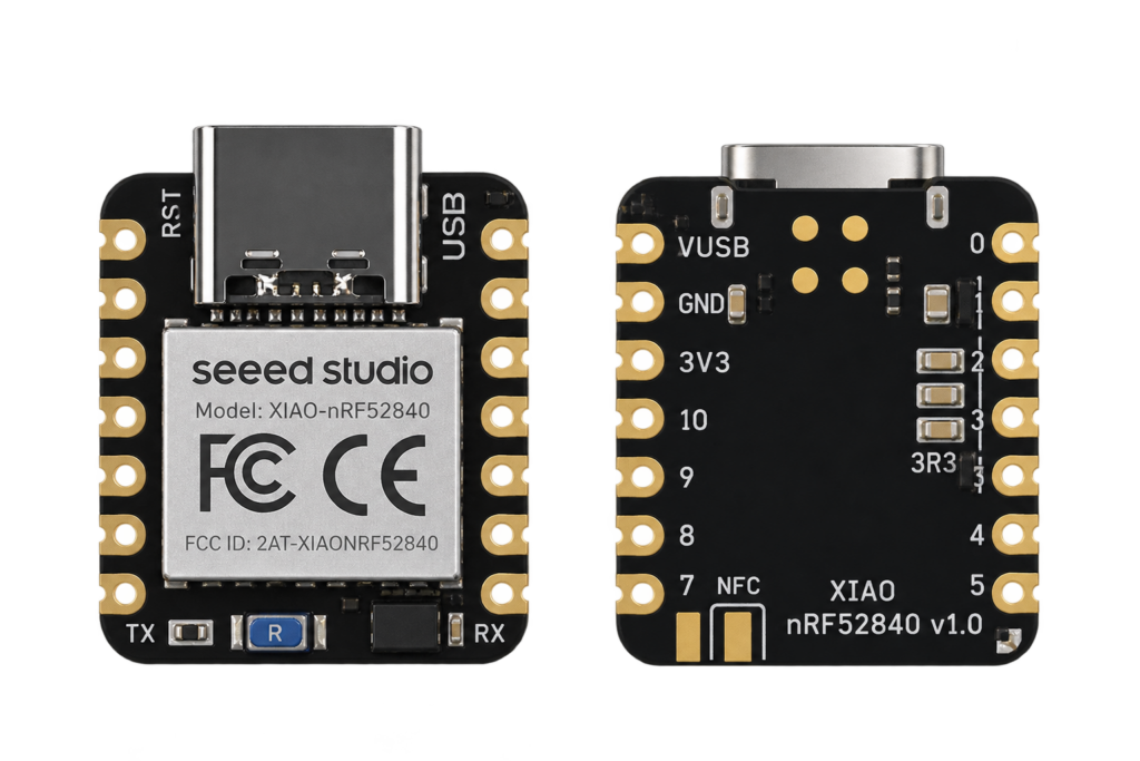
This site's first non-Espressif board: Nordic's nRF52840 Bluetooth Low Energy SoC on Seeed's thumbnail-sized XIAO carrier, with no Wi-Fi radio at all.
Read more
Reference
Seeed Studio XIAO nRF52840 Pinout
This site's first non-Espressif board: Nordic's nRF52840 Bluetooth Low Energy SoC on Seeed's thumbnail-sized XIAO carrier, with no Wi-Fi radio at all.
Read more
 Reference
The Complete Guide to the HC-SR501 PIR Motion Sensor
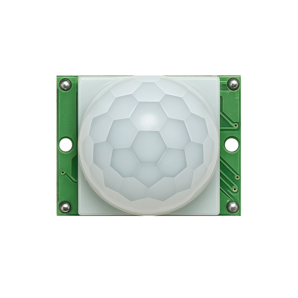
One of the cheapest ways to add motion detection to a project: a passive infrared sensor with adjustable delay and sensitivity, a simple digital HIGH/LOW output, and both retriggerable and non-retriggerable modes.
Read more
Guide
ESP32-C61 Pinout
The complete pin reference for the ESP32-C61: Espressif’s budget Wi-Fi 6 chip, and the exact pins you can safely reuse.
Read more
Reference
The Complete Guide to the HC-SR501 PIR Motion Sensor
One of the cheapest ways to add motion detection to a project: a passive infrared sensor with adjustable delay and sensitivity, a simple digital HIGH/LOW output, and both retriggerable and non-retriggerable modes.
Read more
Guide
ESP32-C61 Pinout
The complete pin reference for the ESP32-C61: Espressif’s budget Wi-Fi 6 chip, and the exact pins you can safely reuse.
Read more
More guides
Keep building.
From ESP32 HomeKit accessories to Arduino and ATtiny reference guides, there’s more where this came from.
All guides