
Reference
NodeMCU-ESP32-C2 Pinout
The pin reference for the NodeMCU-style ESP32-C2 development board: the ESP8684-WROOM-02 module, its exposed GPIOs, and how to flash it over USB-C.
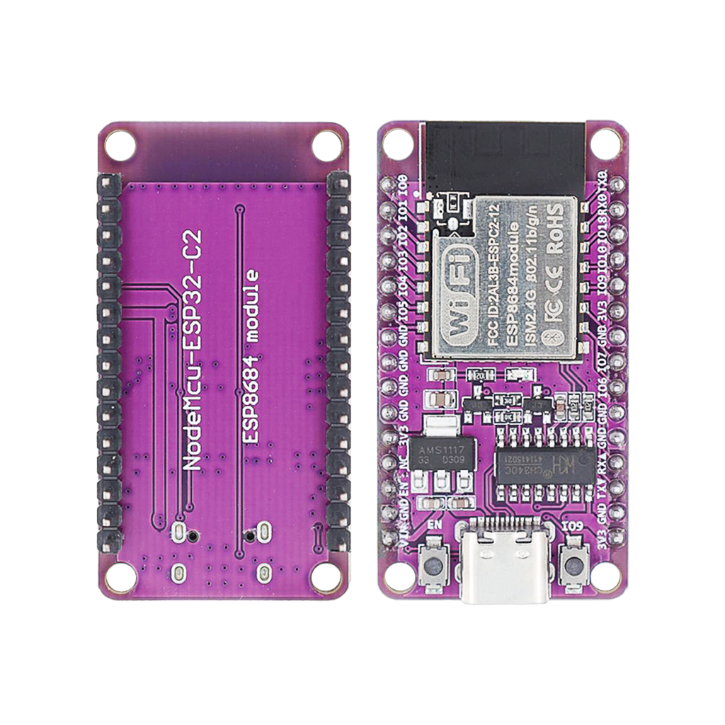
The NodeMCU-ESP32-C2 is a NodeMCU-style development board built around Espressif’s ESP8684-WROOM-02 module, a different, larger module than the bare ESPC2-02 module this site already documents. Same ESP32-C2 chip underneath, more pins broken out and a full USB-C/CH340C programming circuit on board. This guide covers this specific development board: its GPIO layout, communication pins, and how to flash it.
System-on-chip and module
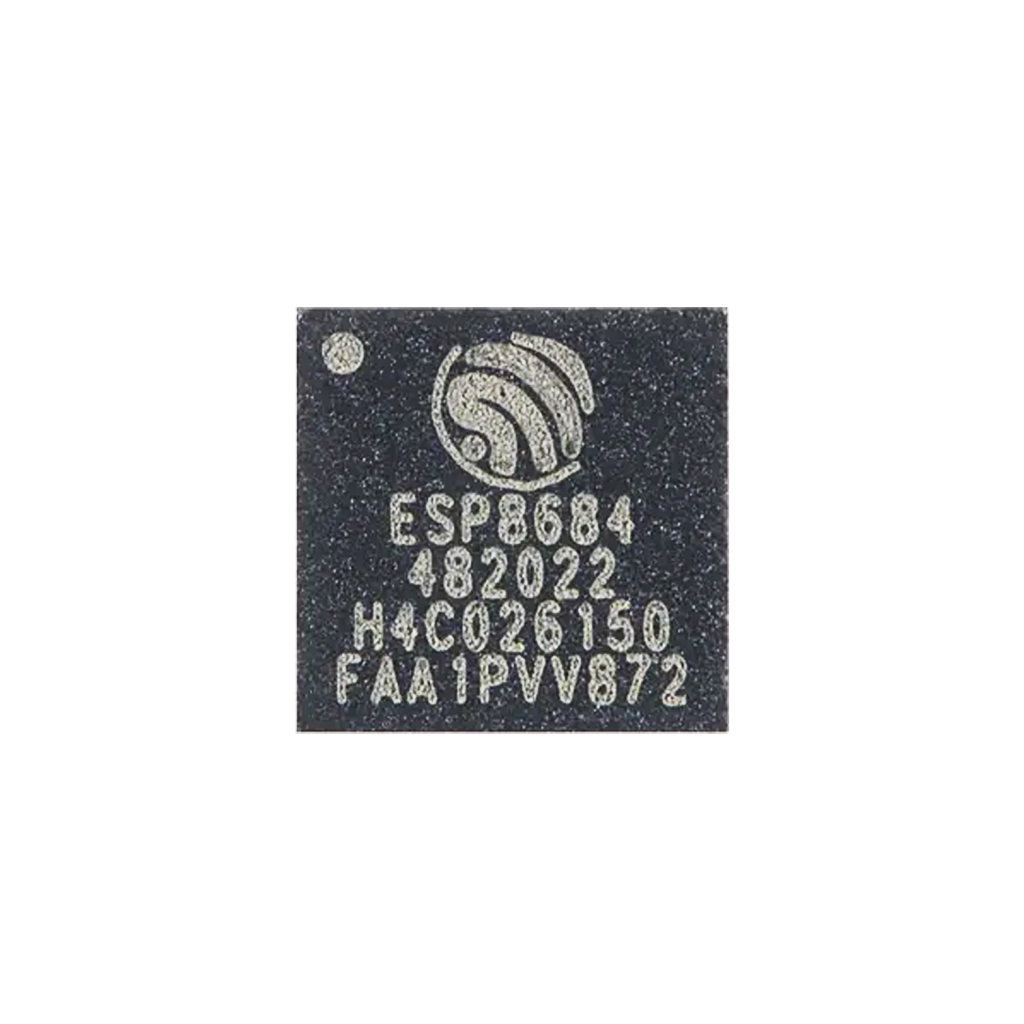
At the heart of this board is the ESP32-C2, marketed name for the ESP8684 chip: a single-core RISC-V SoC from Espressif with integrated 2.4GHz Wi-Fi, a secure bootloader and hardware encryption, built for low-cost, low-resource applications.
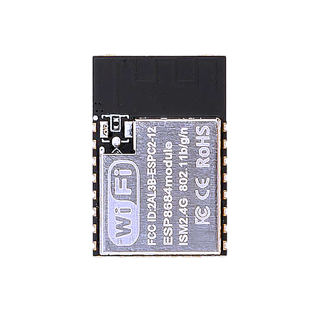
The board carries the ESP8684-WROOM-02 module: the chip, 2MB of SPI flash, a PCB antenna and the surrounding passives in one shielded package.
The development board itself breaks the module’s pins out to a breadboard-friendly, clearly labeled NodeMCU-style header, adds a CH340C USB-to-serial chip, and uses USB-C instead of micro-USB.
Key features
- Wi-Fi 802.11 b/g/n (2.4GHz)
- 12-bit ADC on 5 of the exposed pins
- UART, SPI, I²C and PWM, all software-assignable
- USB-to-serial via onboard CH340C, no separate programmer needed
- USB-C connector
- 2MB flash, embedded in the module
This is a smaller, cheaper board than the ESP32-S3/-C3/-C6 family: fine for simple sensors, wireless switches and other low-power, low-complexity connected devices, not for anything CPU- or memory-heavy.
GPIO quick reference
| GPIO | Function | ADC | PWM | Notes |
|---|---|---|---|---|
| 0 | — | No | Yes | General purpose |
| 1 | ADC1_CH0 | Yes | Yes | Analog input |
| 2 | ADC1_CH1, SPI MOSI | Yes | Yes | |
| 3 | ADC1_CH2, SPI MISO | Yes | Yes | |
| 4 | ADC1_CH3, SPI SCLK | Yes | Yes | |
| 5 | ADC1_CH4 | Yes | Yes | Analog input |
| 6 | I²C SDA | No | Yes | Default I²C pin, remappable |
| 7 | I²C SCL | No | Yes | Default I²C pin, remappable |
| 9 | BOOT strap | No | — | Hold low at reset to enter flash mode |
| 10 | SPI CS | No | Yes | |
| 20 | UART0 TX | No | Yes | To CH340C, to your PC |
| 21 | UART0 RX | No | Yes | From CH340C, from your PC |
All GPIOs are bidirectional digital I/O and support PWM. Remap I²C in Arduino with Wire.begin(SDA, SCL).
Flashing
Thanks to the onboard CH340C, flashing is plug-and-play over USB-C, no external USB-to-serial adapter needed.
- Connect the board via USB-C.
- In Arduino IDE or PlatformIO, select a generic ESP32C2 Dev Module board.
- Click Upload.
- If flashing fails to start automatically, hold IO9 (BOOT) low, tap EN/RESET, release IO9, then retry.
Do not hold IO9 low outside of flashing, it forces the board back into the bootloader instead of running your program.
Conclusion
The NodeMCU-ESP32-C2 trades GPIO count and processing power for cost and simplicity. If a project genuinely only needs Wi-Fi plus a handful of digital/analog pins, this is a cheaper, lower-power alternative to reaching for an ESP-WROOM-32D or ESP32-C3 board. For anything needing more GPIOs, Bluetooth, or more RAM, look at this site’s other ESP32 boards instead.
Related
 Guide
HC-05 Bluetooth Module Pinout
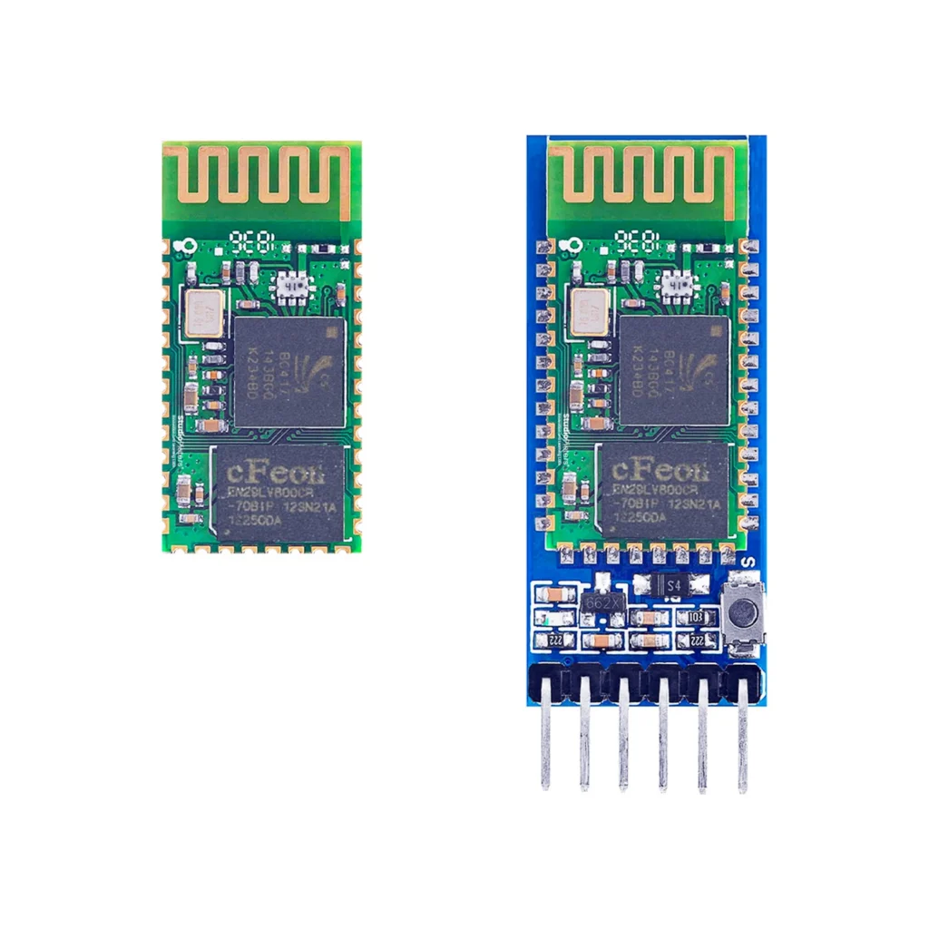
The complete pin reference for the HC-05: a UART-to-Bluetooth bridge available as a bare 34-pin module or a simple 6-pin breakout board.
Read more
Guide
HC-05 Bluetooth Module Pinout
The complete pin reference for the HC-05: a UART-to-Bluetooth bridge available as a bare 34-pin module or a simple 6-pin breakout board.
Read more
 Guide
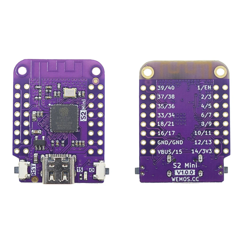
ESP32-S2 Mini Pinout
The complete pin reference for the WEMOS/Lolin S2 Mini: native USB, 14 capacitive touch pins, and no Bluetooth at all.
Read more
Guide
ESP32-S2 Mini Pinout
The complete pin reference for the WEMOS/Lolin S2 Mini: native USB, 14 capacitive touch pins, and no Bluetooth at all.
Read more
 Reference
NeoPixels (WS2812B) – Complete Guide
Individually addressable RGB LEDs that need just one data pin to control hundreds of LEDs, each with its own 24-bit color. This guide covers the WS2812B family, wiring to an ESP32-C6 SUPER MINI, power budgeting, and ESP-IDF/Arduino example code.
Read more
Reference
NeoPixels (WS2812B) – Complete Guide
Individually addressable RGB LEDs that need just one data pin to control hundreds of LEDs, each with its own 24-bit color. This guide covers the WS2812B family, wiring to an ESP32-C6 SUPER MINI, power budgeting, and ESP-IDF/Arduino example code.
Read more
More guides
Keep building.
From ESP32 HomeKit accessories to Arduino and ATtiny reference guides, there’s more where this came from.
All guides